Inhaltsverzeichnis
Werbung
Verfügbare Sprachen
Verfügbare Sprachen
Quicklinks
Werbung
Kapitel
Inhaltsverzeichnis
Fehlerbehebung

Verwandte Anleitungen für ECO-WORTHY NS24L30

Inhaltszusammenfassung für ECO-WORTHY NS24L30
- Seite 1 12V/24V MPPT...
-
Seite 2: Specification Summary
DIMENSIONS Type NS24L30 8.66 5.83 2.52 NS24L40 8.66 5.83 2.52 NS24H50 9.64 6.69 2.68 NS24H60 9.64 6.69 2.68 SPECIFICATION SUMMARY Type NS24L30 NS24L40 NS24H50 NS24H60 Nominal Battery Voltage 12/24V 12/24V 12/24V 12/24V Max.PV Open-Circuit Voltage* 100V 100V 150V 150V Nominal Max.Input Power**... -
Seite 3: Inhaltsverzeichnis
TABLE OF CONCENTS 1.0 Important Safely Instructions 2.0 General Information Features Attached Accessories Optional Accessories 3.0 Installation Instructions General Installation Notes Mounting 4.0 Operation Max Power Point Tracking Technology Battery Charging Load Control Information LED Indications Button And Display 5.0 Trouble Shooting 6.0 Technical Specifications... -
Seite 4: Important Safely Instructions
IMPORTANT SAFETY INSTRUCTIONS SAVE THESE INSTRUCTIONS. This manual contains important safety, installation, and operating for the MPPT solar controller. The following symbols are used throughout this manual to indicate potentially dangerous conditions or mark important safety instructions: WARNING: Indicates a potentially dangerous condition. Be careful when performing related operations. -
Seite 5: Installation Safety Precautions
Installation Safety Precautions WARNING: This unit does not contain GFDI device. Mount the MPPT indoors. Prevent exposure to the elements and do not allow water to enter the controller. Install the MPPT in a location that prevents casual contact. The MPPT heatsink can become very hot during operation. - Seite 6 knowledgeable about batteries, and the proper safety precautions. Be very careful when working with large lead-acid batteries. Wear eye protection and have fresh water available in case there is contact with the battery acid. Remove watches, rings, jewelry and other metal objects before working with batteries.
-
Seite 7: General Information
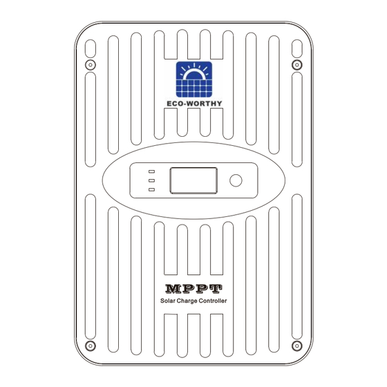
GENERAL INFORMATION 2.1 Features The features of the MPPT are shown in below. An explanation of each feature is provided. 1 – Charging status / Load output status / Error LED 2 – Function button 3 – Digital OLED display 4 –... -
Seite 8: Optional Accessories
5 – User manual 2.3 Optional Accessories The following accessories are available for purchase separately from your authorized dealer: MH-M80(Meter) The digital Remote Meter displays system operating information, error indications. Information is displayed on an OLED display. Additionally, 3 status LEDs provide system status at a glance. -
Seite 9: Installation Instructions
INSTALLATION INSTRUCTIONS 3.1 General Installation Notes water available to wash and clean any contact with battery acid. avoid placing metal objects near the batteries. WARNING: Never install the MPPT in an enclosure with vented/flooded batteries. Battery fumes are flammable and will corrode and destroy the MPPT circuits. -
Seite 10: Mounting
3.2 Mounting Inspect the controller for shipping damage. Do not install directly over an easily combustible surface since the heat sink may get hot under certain operating conditions. For proper air flow, allow at least 15 cm (6 in) of space above and below the controller, and 10 cm (4 in) at the sides. - Seite 11 STEP 4: Drill mounting holes in the wall Measure and mark the distance on the wall, drill 6mm holes and insert plastic expansion particles and tighten. STEP 5: Mount the controller on the wall Align the controller with the mounting hole, tighten the controller to the wall with M4 screws.
-
Seite 12: Operation
Reverse order as power-up. OPERATION 4.1 Max Power Point Tracking Technology Power is the product of voltage and current (Volts x Amps), the following is true*: (1) Power Into the MPPT = Power Out of the MPPT (2) Volts In x Amps In = Volts Out x Amps Out * assuming 100% efficiency i.e. -
Seite 13: Battery Charging
4.2 Battery Charging Charging lead-acid batteries The MPPT has a 4-stage battery charging algorithm for rapid, efficient, and safe battery charging. 1 - CC Stage (Constant Current Charging): Fast Charging 2 - CV Stage (Constant Voltage Charging): Absorption Charging 3 - CF Stage (Floating Charging): Protect the battery from long-term overcharge. And make up the loss of self-discharge 4 - Equalization Stage: Activate battery chemical reaction Charging Lithium ion batteries... -
Seite 14: Load Control Information
LiFePO4-7s 22.4 25.2 18.9 21.7 LiFePO4-8s 25.6 28.8 21.6 24.8 Ternary-3s 11.1 12.6 10.5 Ternary-6s 22.2 25.2 19.2 Ternary-7s 25.9 29.4 22.4 24.5 Custom Custom Custom Custom Custom NOTE: These settings are general guidelines for use at the operator’s discretion. The MPPT can be set to satisfy a wide range of charging parameters. -
Seite 15: Led Indications
When the load output working current is 100%-120% of rated current for 5 mins, load output will be OFF. As soon as load output working current is over 120% of rated current, the load output will be OFF immediately. NOTE: To restart load output, user should set Load Type to “ON” or others manually through controller/APP/meter/PC. -
Seite 16: Button And Display
4.5 Button And Display The controller has a 1.3-inch OLED display and a function button. The user can ONLY set the battery type with preset parameters. Refer to the following figure for specific logic. Note: If need to customize other parameters, you can implement them through optional accessories. -
Seite 17: Trouble Shooting
TROUBLE SHOOTING WARNING: RISK OF ELECTRICAL SHOCK. NO POWER OR ACCESSORY TERMINALS ARE ELECTRICALLY ISOLATED FROM DC INPUT, AND MAY BE ENERGIZED WITH HAZARDOUS SOLAR VOLTAGE. UNDER CERTAIN FAULT CONDITIONS, BATTERY COULD BECOME OVERCHARGED. TEST BETWEEN ALL TERMINALS AND GROUND BEFORE TOUCHING. -
Seite 18: Technical Specifications
PV Over Over input voltage Charging overcurrent CHG Over DisC. Over Discharging overcurrent TECHNICAL SPECIFICATIONS Common Negative MPPT Controller Model: NS24L30 NS24L40 NS24H50 NS24H60 Electrical: Nominal Battery Voltage 12 or 24 Vdc Battery Voltage Range 9 ~ 30Vdc Voltage Accuracy <... - Seite 19 Data & Communications Communication Port Dual RJ45 Comm.Protocols Private protocol and MODBUS PC Software SolarMate Meter MH-M80 / MH-S80 Via RJ45 port Dry Contact Access Voltage Environmental: Ambient Temperature ~ +50 Range Storage Temperature ~ +80 Humidity 100% n.c. IP (Ingress protection) IP42 Protections Reverse Polarity - battery and array...
- Seite 20 1-Way Wire Distance (meters), 12 Volt System Wire Size 10.2 11.7 13.7 16.4 20.5 10.8 13.0 16.2 10.2 Maximum 1-way wire distance for 12 Volt systems, stranded copper, 2% voltage drop 2% Voltage Drop Charts for 75°C Solid Copper Wire 1-Way Wire Distance (feet), 12 Volt System Wire Size (AWG)
- Seite 21 outside of the MPPT. Use 4 AWG (25 mm2) or smaller wire to connect to the MPPT to the splicer block. • The specified wire length is for a pair of conductors from the solar or battery source to the controller (1-way distance) •...
- Seite 22 Efficiency Graphs...
-
Seite 26: Zusammenfassung Der Spezifikation
MASSE ZUSAMMENFASSUNG DER SPEZIFIKATION Type Nominale Batteriespannung Max. PV-Leerlaufspannung* Nominale max. Eingangsleistung** Max. Batterieladestrom Nennlaststrom *Die Array-Spannung sollte diesen Grenzwert niemals überschreiten. **Diese Leistungsgrenzen beziehen sich auf die maximale Wattleistung, die der MPPT verwalten kann. Arrays mit höherer Leistung können verwendet werden, ohne den Controller zu beschädigen. - Seite 27 INHALTSVERZEICHNIS 1.0 Wichtige Sicherheitshinweise 2.0 Allgemeine Informationen Funktionen Beiliegendes Zubehör Optionales Zubehör 3.0 Installationsanweisungen Allgemeine Installationshinweise Montage 4.0 Betrieb Max-Power-Point-Tracking-Technologie Aufladen des Akkus Ladekontrollinformationen LED-Anzeigen Taste und Anzeige 5.0 Fehlerbehebung 6.0 Technische Daten...
-
Seite 28: Wichtige Sicherheitshinweise
WICHTIGE SICHERHEITSHINWEISE ANLEITUNG AUFBEWAHREN. Dieses Handbuch enthält wichtige Sicherheits-, Installations- und Betriebshinweise für den MPPT-Solarregler. Die folgenden Symbole werden in diesem Handbuch verwendet, um auf potenziell gefährliche Bedingungen hinzuweisen oder wichtige Sicherheitshinweise zu kennzeichnen: WARNUNG: Weist auf einen möglicherweise gefährlichen Zustand hin. Seien Sie vorsichtig, wenn Sie damit zusammenhängende Vorgänge ausführen. - Seite 29 Sicherheitsvorkehrungen bei der Installation - - - - - - - - - - - - - - - - - - - - - - - - - - - - - - - - - - - - - - - - - - - - - - - - - - - - - - - - - - - - - - - - - - - - - - - - - - - - - - - - - - - - - - - Batteriesicherheit - - - - - - - - - - - - - - - - - - - - - - - - - - - - - - - - - - - - - - - - - - - - - - - - - - - - - - - - - - - - - - - - - - - - - - - - - - - - - - - - - - - - - - -...
- Seite 30 sich mit Batterien und den richtigen Sicherheitsvorkehrungen auskennen. Seien Sie sehr vorsichtig, wenn Sie mit großen Blei-Säure-Batterien arbeiten. Tragen Sie einen Augenschutz und halten Sie frisches Wasser bereit, falls es zu einem Kontakt mit der Batteriesäure kommen sollte. Legen Sie Uhren, Ringe, Schmuck und andere Metallgegenstände ab, bevor Sie mit Batterien arbeiten.
-
Seite 31: Allgemeine Informationen
ALLGEMEINE INFORMATIONEN 2.1 Funktionen Die Merkmale des MPPT sind unten dargestellt. Eine Erläuterung der einzelnen Funktionen wird bereitgestellt. 1 – Ladestatus / Lastausgangsstatus / Fehler-LED 2 – Funktionstaste 3 – Digitales OLED-Display 4 – Klemmen des Temperatursensors 5 – Zwei serielle RJ45-Kommunikationsports 6 –... -
Seite 32: Optionales Zubehör
5 – Benutzerhandbuch 2.3 Optionales Zubehör Das folgende Zubehör ist separat bei Ihrem autorisierten Händler erhältlich: MH-M80 (Meter) Das digitale Remote Meter zeigt Systembetriebsinformationen und Fehleranzeigen an. Informationen werden auf einem OLED-Display angezeigt. Zusätzlich zeigen 3 Status-LEDs den Systemstatus auf einen Blick. Das Messgerät kann die Parameter des Controllers einfach einstellen. -
Seite 33: Allgemeine Installationshinweise
INSTALLATIONSANLEITUNG 3.1 Allgemeine Installationshinweise Lesen Sie zuerst den gesamten Installationsabschnitt durch, bevor Sie mit der Installation beginnen. Seien Sie sehr vorsichtig, wenn Sie mit Batterien arbeiten. Augenschutz tragen. Halten Sie frisches Wasser bereit, um jeden Kontakt mit Batteriesäure zu waschen und zu reinigen. -
Seite 34: Montage
3.2 Montage Untersuchen Sie die Steuerung auf Transportschäden. Tun nicht direkt über leicht brennbarem Material installieren Oberfläche, da der Kühlkörper darunter heiß werden kann bestimmte Betriebsbedingungen. Lassen Sie für einen ordnungsgemäßen Luftstrom mindestens 15 cm (6 Zoll) Luft frei Freiraum über und unter dem Controller und 10 cm (4 Zoll) an den Seiten. - Seite 35 SCHRITT 4: Bohren Sie Befestigungslöcher in die Wand Abstand an der Wand messen und markieren, 6mm Löcher bohren und Kunststoffdehnpartikel einsetzen und festziehen. SCHRITT 5: Befestigen Sie den Controller an der Wand Richten Sie den Controller mit dem Montageloch aus und befestigen Sie den Controller mit M4-Schrauben an der Wand.
-
Seite 36: Betrieb
BETRIEB 4.1 Max-Power-Point-Tracking-Technologie Leistung ist das Produkt aus Spannung und Strom (Volt x Ampere), es gilt Folgendes*: (1) Leistung in den MPPT = Leistung aus dem MPPT (2) Volt Eingang x Ampere Eingang = Volt Ausgang x Ampere Ausgang * unter Annahme von 100 % Wirkungsgrad, d. h. wenn keine Verluste in Verdrahtung und Wandlung vorhanden wären. -
Seite 37: Aufladen Des Akkus
4.2 Aufladen des Akkus Laden von Blei-Säure-Batterien Der MPPT verfügt über einen 4-stufigen Batterieladealgorithmus für schnelles, effizientes und sicheres Laden der Batterie. 1 - CC-Stufe (Konstantstromladung): Schnellladung 2 - CV-Stufe (Laden mit konstanter Spannung): Absorptionsladen 3 - CF-Stufe (Floating Charging): Schützt den Akku vor langfristiger Überladung. Und den Verlust der Selbstentladung ausgleichen 4 - Ausgleichsphase: Aktivieren Sie die chemische Reaktion der Batterie Aufladen von Lithium-Ionen-Akkus... -
Seite 38: Ladekontrollinformationen
Brauch Brauch Brauch Brauch Brauch 4.3 Ladekontrollinformationen Der Hauptzweck der Laststeuerungsfunktion besteht darin, Systemlasten zu trennen, wenn sich die Batterie auf einen niedrigen Ladezustand entladen hat, und Systemlasten wieder anzuschließen, wenn die Batterie ausreichend aufgeladen ist. Systemlasten können Lichter, Gleichstromgeräte oder andere elektronische Geräte sein. -
Seite 39: Ladesteuerungsmodi
Wenn der Arbeitsstrom des Lastausgangs 5 Minuten lang 100 % bis 120 % des Nennstroms beträgt, wird der Lastausgang ausgeschaltet. Sobald der Arbeitsstrom des Lastausgangs über 120 % des Nennstroms liegt, wird der Lastausgang sofort ausgeschaltet Ladesteuerungsmodi: 1– EIN/AUS-Modus: Der Ein- oder Aus-Zustand. 2 –... -
Seite 40: Taste Und Anzeige
4.5 Taste und Anzeige Der Controller verfügt über ein 1,3-Zoll-OLED-Display und eine Funktionstaste. Der Benutzer kann den Batterietyp NUR mit voreingestellten Parametern einstellen. Siehe die folgende Abbildung für spezifische Logik. -
Seite 41: Fehlerbehebung
FEHLERBEHEBUNG WARNUNG: STROMSCHLAGGEFAHR. KEINE STROM- ODER ZUBEHÖRANSCHLÜSSE SIND ELEKTRISCH VOM DC- EINGANG GETRENNT UND KANN MIT GEFÄHRLICHER SONNENSPANNUNG VERSORGT WERDEN. UNTER BESTIMMTEN FEHLERBEDINGUNGEN KÖNNTE DIE BATTERIE ÜBERLADEN WERDEN. TESTEN SIE ZWISCHEN ALLEN ANSCHLÜSSEN UND DER MASSE, BEVOR SIE SIE BERÜHREN. WARNUNG: Stromschlaggefahr Es ist eine allpolige Trennung der Stromversorgung vorzusehen. -
Seite 42: Zustandsbeschreibung
Zustandsbeschreibung ---------------------------------------------------------------------------------------------------------- Anzeige in Oled Beschreibung Normaler Lauf Kein Fehler HS vorbei Überhitzung des Kühlkörpers PV-Niedrig Niedrige Eingangsspannung BAT Niedrig Batterie schwach BAT vorbei Batterie vorbei PV vorbei Über Eingangsspannung CHG vorbei CHG vorbei Ladeüberstrom Ladeüberstrom Rabatt. Über Überstrom ableiten TECHNISCHE SPEZIFIKATIONEN Gemeinsamer negativer MPPT-Controller Modell:... -
Seite 43: Drahtgrößentabellen
Datenkommunikation Kommunikationsanschluss Dual-RJ45 Privates Protokoll und MODBUS Kommunikationsprotokolle SolarMate PC-Software MH-M80 / MH-S80 Meter Über RJ45-Port Trockenkontakt-Zugriffsspannung Umwelt: Umgebungstemperatur Bereich Lagertemperatur Feuchtigkeit IP (Eindringschutz) Schutz ---------------------------------------------------------------------------------------------------------- Verpolung - Batterie und Array Solarkurzschluss Hohe Kühlkörpertemperatur – Stromminderung Kurzschluss laden Überstrom laden Temperaturgrenze des Kühlkörpers Überspannungs-/Unterspannungsschutz Überspannungs-/Unterspannungsschutz... - Seite 44 1-Wege-Kabelabstand (Meter), 12-Volt-System Drahtstärke (mm2) Maximale 1-Wege-Drahtlänge für 12-Volt-Systeme, verseiltes Kupfer, 2 % Spannungsabfall 2 % Spannungsabfalldiagramme für 75 °C Massivkupferdraht 1-Wege-Kabelabstand (Fuß), 12-Volt-System Drahtstärke (AWG) 1-Wege-Kabelabstand (Meter), 12-Volt-System Drahtstärke (mm2) Maximale 1-Wege-Drahtlänge für 12-Volt-Systeme, Massivkupfer, 2 % Spannungsabfall...
- Seite 45 RJ45-Portdefinition ---------------------------------------------------------------------------------------------------------- Serielle Verbindung (String) von Sonnenkollektoren ----------------------------------------------------------------------------------------------------------...
- Seite 46 Effizienzdiagramme ----------------------------------------------------------------------------------------------------------...