Ripmax Easy Street 2 Bauanleitung
Inhaltsverzeichnis
Quicklinks
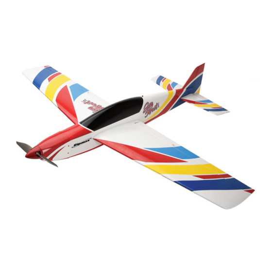
Specification:
Wingspan: 1120mm (44")
Length: 970mm (38")
Flying weight: 1170-1280g (2.6-2.8Ibs)
Radio: 4-5 Channel* Servos: 4x Mini*
*
(Recommendation, not included)
Technische Daten:
Spannweite: 1120mm
Länge: 970mm
Fluggewicht: ca. 1170-1280g
Fernsteuerung: 4...5-Kanal* Servos: 4x Mini*
*
(empfohlen aber nicht enthalten)
Instruction Manual
Bauanleitung
A-ARTF6730
Inhaltsverzeichnis

Verwandte Anleitungen für Ripmax Easy Street 2


Inhaltszusammenfassung für Ripmax Easy Street 2
- Seite 1 Instruction Manual Bauanleitung A-ARTF6730 Specification: Wingspan: 1120mm (44”) Length: 970mm (38”) Flying weight: 1170-1280g (2.6-2.8Ibs) Radio: 4-5 Channel* Servos: 4x Mini* (Recommendation, not included) Technische Daten: Spannweite: 1120mm Länge: 970mm Fluggewicht: ca. 1170-1280g Fernsteuerung: 4...5-Kanal* Servos: 4x Mini* (empfohlen aber nicht enthalten)
-
Seite 3: Inhaltsverzeichnis
2 / 3 Contents Inhalt Required to Complete erforderliches Zubehör Stages Schritte 5 - 19 Completed Model Fertiges Modell Balancing Schwerpunkt Control Throws Ruderausschläge Pre-Flight Checks Vorflug Checks Spare Parts Ersatzteile Flying the Easy Street 2 Den Easy Street 2 Fliegen... -
Seite 4: General Notices
Ripmax shall not be liable for any loss, consequential loss, damage will increase the risk of injury. Always keep yourself at a or expense arising from the improper use or operation in anyway. -
Seite 5: Wichtige Hinweise
Haftungsausschluss: mit sich drehenden Teilen in Berührung kommen! Denken Sie auch an Ihre Haustiere! Ripmax Produkte sind häufig nur ein Teil einer ganzen Funktionskette. Diese Funktionskette, wie auch die Einhaltung der Montage und Betriebsanleitung als auch die Bedingungen und Fliegen Sie grundsätzlich, ob mit Modellflugzeugen-, Hubschraubern- oder Multicoptern, nie in Augenhöhe... -
Seite 6: Required To Complete
INSTRUCTIONS / ANLEITUNG Contents / Inhalt Parts List: Take a moment to identify each of the par ts supplied and read through these Wings. instructions before commencing assembly. Fuselage. Tailplane. Fin and Rudder. Canopy. Fibreglass cowl. Wing spar. Spinner. Control rods. Accessories. - Seite 7 INSTRUCTIONS / ANLEITUNG Stage Schritt The wings and ailerons are supplied with the hinges loose fitted, ready for installation. Remove both ailerons and ensure that the hinges are inserted mid-way in their slots. Using thin cyano, pour a drop onto each hinge – above and below – ensuring the glue soaks into the hinge and surrounding wood on both ailerons.
- Seite 8 INSTRUCTIONS / ANLEITUNG Stage Schritt Fit suitable 200mm extension leads to your aileron servo. It is a good idea to use a lead-lock, a turn of insulation tape or heat shrink tube over the joint for additional security. Carefully tie the end of each servo lead to the length of string installed in the wing.
- Seite 9 INSTRUCTIONS / ANLEITUNG Stage Schritt Locate the aileron control horns and screws. They are screwed into position on the ailerons inline with the aileron servos output arm through the hardwood block. Align the row of holes in the horn with the hinge line. Mark and pilot drill two mounting holes then screw the horn to the aileron.
- Seite 10 INSTRUCTIONS / ANLEITUNG Stage Schritt Slide the aileron servo horn over the wire, re-fit to the servo and snap a moulded keeper onto the pushrod to retain it as shown. Schieben Sie das Querruder Servohorn über den Draht, befestigen Sie dies wieder am Servo, und befestigen Sie einen Sicherungsclip, wie gezeigt.
- Seite 11 INSTRUCTIONS / ANLEITUNG Stage Schritt Cut the film away from the wing mounting holes and the bolt hole on both sides of the fuselage. Entfernen Sie die Folie über den Flächenbefestigungen sowie für die Befestigung auf beiden Seiten des Rumpfes. Stage Schritt There are a series of cooling holes in underside of the fuselage.
- Seite 12 INSTRUCTIONS / ANLEITUNG Stage Schritt Mark the tailplane on the top and bottom where it enters the fuselage using a soft, water- soluble pen. Markieren Sie mit einem wasserlöslichen Stift das Heckleitwerk auf der Ober- und Unterseite, wo es in den Rumpf geht. Stage Schritt Remove the tailplane and cut away the covering from just inside...
- Seite 13 INSTRUCTIONS / ANLEITUNG Stage Schritt Cut the film from the elevators for the elevator joiner. Test fit the elevator’s and ensure that the joiner and hinges are a snug fit. Entfernen Sie die Folie am Leitwerk für den Ruderverbinder. Prüfen Sie, ob die Ruder gut passen. Stage Schritt Add some slow setting epoxy to the elevator slots and proceed...
- Seite 14 INSTRUCTIONS / ANLEITUNG Stage Schritt Using thin cyano, pour a couple of drops onto each hinge - above and below - ensuring the glue soaks into the hinge and the surrounding wood. Geben Sie etwas Sekundenkleber auf jedes Scharnier – oben und unten - und stellen Sie sicher, dass dieser vom Scharnier und dem umgebenden Holz aufgesogen wird.
- Seite 15 INSTRUCTIONS / ANLEITUNG Stage Schritt Using epoxy, glue the fin in its slot. Use masking tape to protect the covering whilst you do this (removing it as soon as you are satisfied with the alignment and before the epoxy cures). Verwenden Sie Epoxidharz Kleber, um die Finne in dem Schlitz einzukleben.
- Seite 16 INSTRUCTIONS / ANLEITUNG Stage Schritt Locate the tail skid and the holes for the tail skid at the rear of the fuselage, and then glue the tail skid into the fuselage as shown. Kleben Sie den Hecksporn wie gezeigt in die beiden Bohrungen am Ende des Rumpfes.
- Seite 17 INSTRUCTIONS / ANLEITUNG Stage Schritt Now locate the elevator control horn. Using the elevator push rod as a guide slide it down the tube in the fuselage from the elevator position on the top of the left hand side. (Looking from the rear) mark and pilot drill its mounting holes position.
- Seite 18 INSTRUCTIONS / ANLEITUNG Stage Schritt Form a 90° bend in the pushrod at this marked point using a pair of pliers. Biegen Sie das Gestänge mit einer Zange an der markierten Position um 90°. Stage Schritt Slide the servo horn down the bent pushrod and clip on a moulded swing-in keeper.
- Seite 19 INSTRUCTIONS / ANLEITUNG Stage Schritt Fit your choice of brushless outrunner motor using the screws supplied into the captive nuts pre-fitted in the motor mount. Feed the motor wires through the bulkhead. Montieren Sie Ihren ausgewählten Brushless Aussenläufer Motor, und verwenden dafür die Schrauben, die mit den montierten Muttern am Motorträger mitgeliefert wurden.
- Seite 20 INSTRUCTIONS / ANLEITUNG Stage Schritt To set the cowl/spinner clearance, attach some foam tape to the back of the back plate to act as a spacer. Position the cowl and bolt on the spinner back plate to get the clearance correct. Zum Einstellen des Abstandes der Motorhaube und des Spinners befestigen Sie einige Schaumstoffbänder an der Rückseite der Spinnerplatte.
-
Seite 21: Fertiges Modell
INSTRUCTIONS / ANLEITUNG Stage Schritt The canopy slots into place locating over the bolts in the firewall and is retained with a small catch at the rear. Setzen Sie die Kabinenhaube in die Schlitze und rasten Sie diese am hinteren Ende ein. Completed Model / Fer tiges Modell You are now ready to apply the supplied decals. -
Seite 22: Spare Parts
Ruder ohne Widerstand frei bewegen können, und sich nicht verwinden. Spare Par ts / Ersatzteile Spare parts are available for the Easy Street II from all Ripmax stocked model shops. In case of any difficulty, any product queries, or to locate your local Ripmax stockist, please visit www.ripmax.com Ersatzteile sind für den Easy Street II in allen Ripmax Modellfachgeschäften verfügbar. -
Seite 23: Flying The Easy Street
Flying the Easy Street / Den Easy Street Fliegen The Easy Street 2 is designed as a general use sports model, the type that you can just throw in the back of the car and fly in almost any weather at short notice. It has flying characteristics somewhere inbetween a sports model and a precision pattern plane. A hand launch is uneventful and simply requires a straight over arm throw about 10 degrees upwards from level at around 60-75% throttle. - Seite 24 Copying or reproduction, even in parts require written schriftlicher Genehmigung der Ripmax Ltd. permission of Ripmax Ltd. Made in China Manufactured for and distributed to your local model shop by: Ripmax Ltd., 241 Green Street, Enfield, EN3 7SJ. United Kingdom.