Werbung
Quicklinks
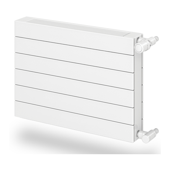
M o n t a g e a n l e i t u n g K O N T E C - K o n v e k t o r Ty p e K K
I n s t a l l a t i o n I n s t r u c t i o n s - K O N T E C C o n v e c t o r Ty p e K K
a n d H o r i z o n t a l H e a t i n g W a l l P a n e l Ty p e K H
ACHTUNG: Bei der Montage von Heizkörpern ist zu beachten, dass die
Befestigung von Heizkörpern so dimensioniert wird, dass sie für die
bestimmungsgemäße Verwendung und vorhersehbarer Fehlanwendung
geeignet ist. Hierbei sind insbesondere die Verbindung mit dem Baukörper
sowie dessen Beschaffenheit, die Geeignetheit des Montagezubehöres und
die möglichen Belastungen nach erfolgter Montage zu prüfen.
ZU VERWENDENDE AUFHÄNGUNGEN
MIT AUFGESCHWEISSTEN LASCHEN:
• KK: VONOMAT-Schnellmontagekonsole für BH 214 bzw. BH 286 bei
Type KK 11, KK 22, KK 23 und KK 34.
• KH: VONOMAT-Schnellmontagekonsole ab BH 386 für alle KH Typen.
• Die entsprechenden Montageanleitungen sind den jeweils verwendeten
Befestigungssets zu entnehmen.
OHNE AUFGESCHWEISSTE LASCHEN:
• KK: VN-Stand -bzw. VN-Wandkonsolen.
• KH: Standkonsole SK 23 für KH 11, KH 21, KH 22 bei BH 358 bis BH 718
und Standkonsole SK 22 für KH 20 bei BH 358 bis BH 574.
• Die entsprechenden Montageanleitungen sind den jeweils verwendeten
Befestigungssets zu entnehmen.
MONTAGEHINWEISE FÜR KK BZW. KH
MIT AUFGESCHWEISSTEN LASCHEN
BEI VERWENDUNG DER VONOMAT SCHNELLMONTAGEKONSOLE:
• An den Stirnflächen der Schutzecken die Schrumpffolie öffnen.
• Schutzecken entfernen und den darunterliegenden Karton mittels Tapezier-
messer vorsichtig im Bereich der Aufhängelaschen aufschneiden.
• Ab BL 2200 ist ein drittes Laschenpaar (Baulängenmitte) vorhanden. Das
in der Mitte liegende Aufhängelaschenpaar vorsichtig mit dem Tapezier-
messer freistellen.
• Befestigung der Wandschiene laut Laschenaufschweißbild.
• KK bzw KH -Montage nach Montageanleitung der VONOMAT-Schnell-
montagekonsole durchführen.
MONTAGEHINWEISE FÜR KK BZW. KH
OHNE AUFGESCHWEISSTE LASCHEN
1.)BEI VERWENDUNG DER VN-STAND -BZW. VN-WANDKONSOLE:
• Schrumpffolie an der Unterseite des Heizkörpers öffnen.
• Schutzecken entfernen und den Karton mittels Tapeziermesser
vorsichtig, im vorgegebenen Montagebereich der verwendeten VN-
Konsole, ausschneiden.
• Positionierung der Konsolen nach Skizze A.
• Montage des Heizkörpers laut Montageanleitung der verwendeten Konsole.
2.)BEI VERWENDUNG DER SK 22 ODER SK 23:
• Gleiche Vorgehensweise wie in Punkt 1. beschrieben.
MONTAGEHINWEISE FÜR KK-S
(BH 70, 142, 214 UND 286)
Diese KK-S haben einen integrierten Strahlungsschirm, der sich auf der
gegenüberliegenden Seite dieser Montageanleitung befindet. Montage
mittels VN- Standkonsole.
HINWEIS: Die vorgegebene Anschlusssituation muss umbedingt
eingehalten werden !!!
LASCHENAUFSCHWEISSBILD
BRACKET WELDING DIAGRAM
X
BL/2
BH
X
Y
Z
214
160
85
120
286
160
130
120
358
160
130
220
430
160
130
220
502
160
130
220
574
160
130
420
Achtung: Die zulässige Druckstufe (5,0 bzw 8,0 bar) und die zuläs-
sige Temperatur (110 °C) sind einzuhalten.
u n d K O N T E C - H o r i z o n t a l h e i z w a n d Ty p e K H
X
BL/2
BH
X
Y
Z
646
160
130
420
718
160
130
420
790
160
130
420
3. Laschenpaar ab BL 2200 mm
rd
3
pair of brackets from OL 2200 mm
ATTENTION:For the correct installation of radiators it is essential that the
fixing of the radiator is carried out in such a way that it is suitable for
intended use AND predictable misuse. A number of elements need to be
taken into consideration including the fixing method used to secure the
radiator to the wall, the type and condition of the wall itself, and any
additional potential forces or weights, prior to finalising installation.
D
MOUNTINGS TO BE USED
WITH WELDED BRACKETS:
• KK: VONOMAT quick-fit bracket for OH 214 or OH 286 for models KK 11,
KK 22, KK 23 and KK 34.
• KH: VONOMAT quick-fit bracket from OH 386 for all KH models.
• The relevant installation instructions can be found in the fixing kits used.
WITHOUT WELDED BRACKETS:
• KK: VN floor brackets or VN wall brackets.
• KH: SK 23 floor brackets for KH 11, KH 21, KH 22, OH 358 to 718 and
SK 22 floor brackets for KH 20, OH 358 to 574.
• The relevant installation instructions can be found in the fixing kits used.
HINTS FOR INSTALLATION OF KK OR KH
D
WITH WELDED BRACKETS
WHEN USING VONOMAT QUICK-FIT MOUNTING BRACKET:
• Open the shrink wrapping on the corner protector front faces.
• Remove the corner protectors and carefully cut the cardboard behind in
the area of the mounting brackets using a wallpaper knife.
• From OL 2200, a third pair of brackets is provided (centre of overall
length). Carefully free the central pair of brackets using the wallpaper
knife.
• Fit the wall rail in accordance with the bracket welding diagram. Fit the
KK or KH in accordance with the VONOMAT quick-fit mounting bracket
fitting instructions.
HINTS FOR INSTALLATION OF KK OR KH
D
WITHOUT WELDED BRACKETS
1.) WHEN USING VN FLOOR MOUNTING OR
VN WALL MOUNTING BRACKET:
• Open the shrink wrapping on the underside of the heater.
• Remove the corner protectors and, using a wallpaper knife, carefully
cut the cardboard in the fitting area shown for the VN bracket used.
• Position the brackets as shown in diagram A.
• Fit the heater in accordance with the fitting instructions for the bracket used.
2.) WHEN USING SK 22 OR SK 23:
• Proceed as described under 1.).
HINTS FOR INSTALLATION OF KK-S
D
(OH 70, 142, 214 AND 286)
These KK-S are fitted with an integral radiation reflector on the opposite
side of these fitting instructions. Fit using the VN standard bracket.
NOTE: The connecting position shown must be adhered to !!!
KONSOLENPOSITIONIERUNG (SKIZZE A)
BRACKET POSITIONING (DIAGRAM A)
a
SK
22
SK
23
WK
10 - 13
SK
10 - 19
Important: The permissible pressure level (5.0 or 8.0 bar) and the
permissible temperature (110 °C) must be adhered to.
VOGEL
NOOT
&
BL/2
BL/2
SK 10 - 23: 3
rd
bracket from OL 2200 mm
WK 10 - 13: No. of brackets according to
a = 110 mm
fitting instructions enclosed with bracket
a = 165 mm
a = 150 mm
SK 10 - 23: 3. Konsole ab BL 2200 mm
a = 150 mm
WK 10 - 13: Konsolenanzahl laut der
Konsole beiligender Montageanleitung.
GB
GB
GB
GB
a
KMAA05
Werbung

Verwandte Anleitungen für Vogel&Noot KONTEC KK


Inhaltszusammenfassung für Vogel&Noot KONTEC KK
- Seite 1 M o n t a g e a n l e i t u n g K O N T E C - K o n v e k t o r Ty p e K K u n d K O N T E C - H o r i z o n t a l h e i z w a n d Ty p e K H I n s t a l l a t i o n I n s t r u c t i o n s - K O N T E C C o n v e c t o r Ty p e K K a n d H o r i z o n t a l H e a t i n g W a l l P a n e l Ty p e K H ACHTUNG: Bei der Montage von Heizkörpern ist zu beachten, dass die...
- Seite 2 I n s t r u c t i o n s d e m o n t a g e p o u r c o n v e c t e u r K O N T E C t y p e K K e t p a n n e a u c h a u f f a n t h o r i z o n t a l K O N T E C t y p e K H I n s t r u k c j a m o n t a ż...