Roca ATAI 5A2734 Bedienungsanleitung
Inhaltsverzeichnis
Verfügbare Sprachen
Verfügbare Sprachen
Quicklinks
Inhaltsverzeichnis
Fehlerbehebung

Verwandte Anleitungen für Roca ATAI 5A2734


Inhaltszusammenfassung für Roca ATAI 5A2734
- Seite 1 ATAI 5A2734...
-
Seite 3: Schéma De Décomposition
27 26 29 28 Fig. A... - Seite 4 Fig. B...
- Seite 5 SOMMAIRE A) Schéma de décomposition ......2-3 B) Données techniques ....... 12 C) Instruction de montage .
-
Seite 16: Bauteile Des Artikels
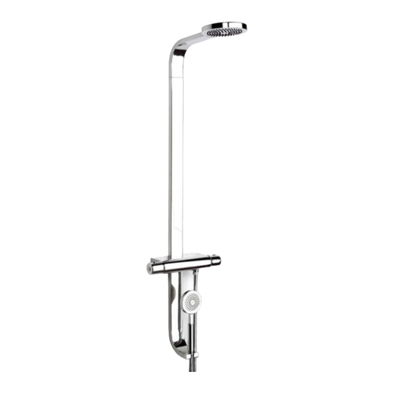
TECHNISCHE INFORMATIONEN: Bauteile des Artikels (abb. A) 1. Abschlussplättchen 19. Gehäuse 38. Sprudlermembran 2. Schraube 20. Gewindestift 39. Sprudlerdiffusor 3. Thermostatknauf 21. O-Ring 40. O-Ring 4. O-Ring 22. Stutzen 41. Stutzen 5. Feder 23. Dichtung 42. Kniestück 6. Druckknopf 24. Brauseschlauch 43. -
Seite 17: Benutzungshinweise
Oberkante waagerecht liegt. Die zwei Gruppen mit der gleichen Tiefe A- hinsichtlich der Wand bleiben müssen,mit Schablone -51- nachprüfen, dass die Tiefe des zwei Gruppen zwischen der Abstand Min und Max auf die Schablone angegeben, sind. Nachdem die Exzenterschäfte positioniert wurden, ist mit Hilfe der darauf aufgesetz- ten Schablone eine Bohrung in die Wand einzubringen. -
Seite 18: Fehlersuche Und Abhilfe
FEHLERSUCHE UND ABHILFE: PROBLEM MÖGLICHE URSACHEN ABHILFEN Wesentliche Verringerung der • Ungenügender Förderdruck • Förderseitige Anlage kontrollieren Durchflussmenge • Filter verstopft • Filter reinigen • Kartusche nicht ausreichend festgezogen • Nutmutter schließen Austretendes Wasser • O-Ringe abgenutzt Zustand der O-Ringe kontrollieren unter dem Hebelgriff (Reinigung oder Wechsel) •... - Seite 25 Ø95 150 15 G1/2" 1000 1100 1200 1800 1900 2000 2100...
-
Seite 26: Esquema De Montaje
Fig. C Fig. D... - Seite 27 Fig. E Fig. F...
- Seite 28 Roca Sanitario, S.A. Avda. Diagonal, 513 08029 Barcellona SPAIN Teléfono 93 366 1200 93 419 4501 www.roca.es...