Inhaltsverzeichnis
Werbung
Quicklinks
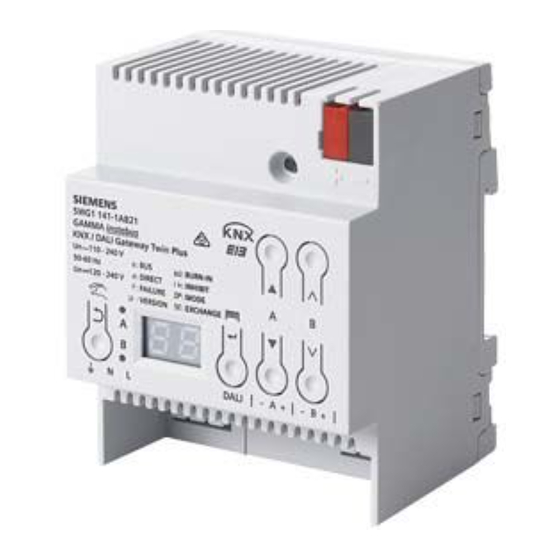
Gamma instabus
KNX/DALI Gateway Twin N 141/31
5WG1 141-1AB31
KNX/DALI Gateway Twin plus N 141/21
5WG1 141-1AB21
KNX/DALI Gateway plus N 141/03
5WG1 141-1AB03
Bedien- und Montageanleitung
Operating and Mounting Instructions
Stand: Juni 2014
Issued: June 2014
AC 230V
PE
N
L
N 141/31
KNX/DALI Gateway Twin
+
-
+
-
N
L
Bild / Figure 1
AC 230V
N
L
L` PE
N 141/21
K NX /DA LI G ateway Tw in plus
+
-
+
-
N
L
Bild / Figure 2
Eigenschaften nur für N 141/21 und N 141/03 sind grau markiert
L1V30319776A - DS02
Produkt- und Funktionsbeschreibung
Das KNX/DALI Gateway Twin bzw. Twin plus und plus
ist ein KNX-Gerät mit zwei unabhängigen bzw. einer
DALI-Schnittstellen, an die pro Kanal bis zu 64 DALI-
Aktoren (z.B. EVG mit DALI-Schnittstelle) und zusätzlich
DALI-Sensoren (z.B. DALI-Tasterschnittstelle, Präsenz-
melder) anschließbar sind. Die drei Varianten unter-
scheiden sich nur im Funktionsumfang, nicht in der
Installation. Alle zusätzlichen Funktionen der Variante
plus N 141/21 bzw. N 141/03 sind in diesem Dokument
grau markiert.
DALI (Digital Addressable Lighting Interface) ist eine
bidirektionale Kommunikations-Schnittstelle nach IEC
62386, deren Spezifikation von Herstellern für elektro-
nische Vorschaltgeräte (EVG) festgelegt wurde. Diese
ermöglicht nicht nur das Empfangen von z.B. Schalt-
und Dimmbefehlen, sondern auch das Senden von
Status-Information, wie z.B. den Ausfall eines Leucht-
mittels oder die Meldung eines erkannten Fehlers im
Vorschaltgerät. Die DALI-Aktoren (EVG) lassen sich in
Gruppen oder einzeln schalten und dimmen. Es
ermöglicht außerdem das Erfassen und Übertragen von
DALI-Status- und Fehlermeldungen. Den einzelnen
DALI-EVG werden bei der Inbetriebnahme mit der ETS
(Engineering Tool Software) ein individueller Name,
D ALI EVG
eine Gruppe, einem EVG, Parameter und Szenen
D ALI EC G 1..64
zugewiesen. Die Zuweisung der DALI-Sensoren zu den
Gruppen erfolgt ebenfalls in der ETS (siehe hierzu die
+
+
+
+
D ALI
Applikationsprogrammbeschreibung).
-
-
-
-
Das integrierte Netzgerät dient zur Versorgung der
N
Gateway-Elektronik und zur Erzeugung der DALI-
PE
PE
PE
PE
Busspannung. Die DALI-Spannungsversorgung versorgt
L
L
L
sowohl EVG als auch Sensoren, wobei auf die maximal
zulässige Stromaufnahme aller angeschlossenen DALI-
Geräte zu achten ist.
Weitere Informationen
Leuchtstofflampe/LED
http://www.siemens.de/gamma-td
fluor escent lamp/LED
D ALI EVG
D ALI EC G
64
Anschlussbeispiel
A
B
+
+
+
+
+
D ALI
Bild 1: N 141/31 EVG mit Sensoren
D ALI
C
-
-
-
-
-
D
Bild 2: N 141/21 EVG mit Stand-by Abschaltung über
Schaltaktor, Kanal B entfällt bei N 141/03
N
PE
PE
PE
PE
L
L
L
Technische Daten
+
Spannungsversorgung
-
· KNX Busspannung: erfolgt über die Buslinie
· KNX Busstrom: 5 mA
Leuchtstofflampe
· Elektronik und DALI-Schnittstelle:
fluor escent l amp
- integriertes Netzgerät für
·
·
- Leistungsaufnahme: max. 11 W (N 141/31 -/21)
Ein-/ Ausgänge
D ALI EVG
D ALI EC G 1..64
· Netzanschluss: 3-polig (L, N, Erde)
· DALI-Schnittstelle nach IEC 62386:
+
+
+
+
- max. 64 DALI-EVG pro Kanal (je max. 2mA)
D ALI
-
-
-
-
mit > 8kOhm Eingangsimpedanz
- max. Anzahl von Sensoren pro Kanal abhängig von
N
der Stromaufnahme der Sensoren
PE
PE
PE
PE
(typ. 10 mit je ca. 6mA)
L
L
L
- DALI-Spannungsversorgung pro Kanal:
- ca. DC 19 V, potentialfrei, kurzschlussfest
- max. Strom: I
- max. garantierter Strom: In
- Leitungslänge DALI
Leuchtstofflampe/LED
- Ø 1,5 mm²
fl uor escent lamp/LED
- Ø 1,0 mm²
D ALI EVG
- Ø 0,75 mm² max. 174 m
D ALI EC G
64
- Ø 0,5 mm²
A
B
+
+
+
+
+
D ALI
D ALI
Anschlüsse
C
-
-
-
-
-
D
· Steckklemmen für Netzspannung und DALI-
Schnittstelle, Abisolierlänge 10 ... 11 mm (siehe
N
PE
PE
PE
PE
Prägung am Gerät)
L
L
L
· Es sind folgende Leiterquerschnitte zulässig:
-
0,5 ... 2,5 mm
+
D ALI
-
0,5 ... 2,5 mm
-
0,5 ... 2,5 mm² feindrähtig unbehandelt
-
-
AWG 20 (0,75 mm²) – AWG 12 (3,3 mm²)
solid, stranded
Leuchtstoffl ampe
fluorescent lamp
· Die Netzzuleitung zum Gerät ist mit einem
Leitungsschutzschalter der Charakteristik B oder
C für einen max. Nennstrom von 6 A abzusichern!
· KNX Bus: Busklemme
D
AC 110-240 V, 50-60 Hz
DC 120-240V
max. 6W (N 141/03)
= 250 mA
max
= 190 mA
max
max. 300 m
max. 238 m
max. 116 m
2
eindrähtig
2
mehrdrähtig
Seite 1 von 6
GB
Product and Applications Description
The KNX/DALI Gateway Twin or Twin plus and plus is a
KNX device with two independent or one DALI
interfaces. It can be connected to up to 64 DALI
actuators (e.g. ECG with DALI interface) and additional
DALI sensors (e.g. DALI pushbutton interface, presence
detectors) per channel. The variants differs only in
functionality, not in installation. All additional features
of Twin plus N 141/21 and N 141/03 are marked within
this document with grey background.
DALI (Digital Addressable Lighting Interface) is a
bidirectional communications interface to IEC 62386,
whose specification was chosen by manufacturers for
electronic control gears (ECG). It not only receives, for
example, switching and dimming commands, but also
transmits status information such as failure of an
illuminant or reporting of a detected error in the
ballast. The gateway communicates with up to 64 DALI
actuators per channel. These can be connected and
dimmed in groups or single. It also records and
transfers DALI status and error messages. An individual
name, a group, a ECG, parameter and scenes are
assigned to individual DALI ECG during commissioning
with the ETS (Engineering Tool Software). DALI sensors
are also assigned to groups in the ETS (for this, go to
the application program description).
The integrated power supply unit supplies the gateway
electronics and generates the DALI bus voltage. The
DALI power supply feeds both ECG and sensors; verify
that the maximum permissible current drain by all
connected DALI devices is not exceeded.
Additional Information
http://www.siemens.com/gamma-td
Example of Operation
Figure 1: N 141/31 ECG with sensors
Figure 2: N 141/21 ECG with stand-by shut-down
over load switch, channel B left for N 141/03
Technical Specifications
Power supply
· KNX bus voltage: carried out via the bus line
· KNX bus current: 5 mA
· Electronics and DALI interface:
- Integrated power supply for
·
AC 110-240 V, 50-60 Hz
·
DC 120-240V
- Power consumption: max. 11 W (N 141/31 -/21)
max. 6W (N 141/03)
Inputs/outputs
· Mains connection: 3-pole (L, N, earth)
· DALI interface according to IEC 62386:
- max. 64 DALI devices per channel (each max. 2
mA)with > 8 kOhm input impedance
- max. amount of sensors per channel depends on
current consumption of sensors (typ. 10 with 6
mA each)
- DALI power supply per channel:
- approx. DC 19 V, floating, short-circuit-proof
- max. current I
= 250 mA
max
- max. guaranteed current: In
- Wiring length DALI
- Ø 1.5 mm²
max. 300 m
- Ø 1.0 mm²
max. 238 m
- Ø 0.75 mm² max. 174 m
- Ø 0.5 mm²
max. 116 m
Connections
· Plug-in terminals for mains voltage and DALI
interface, insulation strip length 10 ... 11 mm
· The following conductor cross-sections are permit-
ted:
-
0.5 ... 2.5 mm
2
single-core
-
0.5 ... 2.5 mm
2
stranded multi-core
0.5 ... 2.5 mm² finely stranded, untreated
-
-
AWG 20 (0.75 mm²) – AWG 12 (3.3 mm²)
solid, stranded
· The supply cable to the device must be fused
with a circuit-breaker of characteristic B or C for a
max. nominal current of 6 A!
· KNX bus: bus terminal
features for N 141/21 and N 141/03 only marked in grey
page 1 of 6
= 190 mA
max
Werbung
Inhaltsverzeichnis

Verwandte Anleitungen für Siemens instabus KNX/DALI Gateway Twin N 141/31


Inhaltszusammenfassung für Siemens instabus KNX/DALI Gateway Twin N 141/31
- Seite 1 Busspannung. Die DALI-Spannungsversorgung versorgt sowohl EVG als auch Sensoren, wobei auf die maximal zulässige Stromaufnahme aller angeschlossenen DALI- Geräte zu achten ist. Weitere Informationen Additional Information Leuchtstofflampe/LED http://www.siemens.de/gamma-td http://www.siemens.com/gamma-td fluor escent lamp/LED D ALI EVG D ALI EC G Anschlussbeispiel Example of Operation...
- Seite 2 · Any faulty device is to be sent together with a return www.siemens.de/automation/support-request zuständigen Vertriebsniederlassung zurückzusenden. delivery note of the local Siemens office. Bei zusätzlichen Fragen zum Produkt wenden Sie sich · · If you have further questions concerning the bitte an unseren Technical Support.
- Seite 3 Geräteinfo-Anzeige Device info-Display 1) Statusanzeige 1) Status indication Display Beschreibung Description Fehler (blinkt) Failure (flashing) An den DALI-Klemmen A10 bzw. A11 wurde Fremdspannung erkannt. Incorrect voltage detected at DALI terminals A10 and A11. Fremdspannungserkennung Incorrect voltage detection Υ Das Gerät ist mit einer Fremspannungserkennung an den beiden DALI- The device is fitted with a voltage detector on both DALI channels.
-
Seite 4: Menüfunktionen
2) Menüfunktionen 2) Menu functions Durch Drücken von A6 „Menü“ lassen sich Informationen abrufen. Die Auswahl Pressing A6 "Menu" calls up information. Selection is performed by A7 erfolgt durch A7 . Mit Drücken von A6 „OK“ gelangt man weiter, mit A3 Press A6 "OK"... -
Seite 5: Leuchtmittel Einbrennen
Taste / Button Anzeige Beschreibung Description Defektes EVG durch ein neues EVG (Auslieferungszustand) Disconnect one faulty ECG and connect the new ECG (factory-default) tauschen Umschalten auf Menü mit A6 Use A6 to enter the menu Nach mehrmaligen Drücken von A7 Menüpunkt „SE“ Select by using A7 „SE“. -
Seite 6: Standardanwendungen Konfigurieren
Use A7 to select „OP“ anwendungen“ Nach Drücken auf A6 wird der zuletzt gewählte Modus angezeigt. Use A6 to display the last selected mode. Weitere Informationen siehe APB: www.siemens.de/gamma-td More information see APB: www.siemens.com/gamma-td A0 - Basisfunktion A0 – Basic function A1 - manueller Betrieb A A1 –...