Werbung
Quicklinks
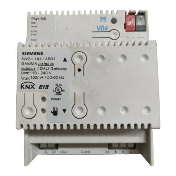
Gamma instabus
instabus / DALI Gateway N 141
5WG1 141-1AB01
Bedien- und Montageanleitung
Operating and Mounting Instructions
Stand: April 2006
As at: April 2006
AC 230V
PE
L
instabus / DALI Gateway
N 141
+
-
PE
N
L
Bild / Figure 1
A5E00675540A
DS02
Produkt- und Funktionsbeschreibung
Das instabus / DALI Gateway N 141 ist ein KNX EIB-Gerät mit ei-
nem DALI-Ausgang, an den bis zu 64 DALI-Aktoren (z.B. EVGs
mit DALI-Schnittstelle) anschließbar sind. DALI-Sensoren dürfen
an den Ausgang des N 141 nicht angeschlossen werden.
DALI (Digital Addressable Lighting Interface) ist eine bidirektio-
nale Kommunikations-Schnittstelle nach IEC 60929, deren Spe-
zifikation von Herstellern für elektronische Vorschaltgeräte
festgelegt wurde. Sie ermöglicht nicht nur das Empfangen von
z.B. Schalt- und Dimmbefehlen sondern auch das Senden von
Status-Information, wie z.B. den Ausfall eines Leuchtmittels o-
der die Meldung eines erkannten Fehlers im Vorschaltgerät.
Nach IEC 60929 sind an eine DALI-Busleitung bis zu 64 DALI-
Geräte anschließbar, denen jeweils eine individuelle Teilneh-
mer-Adresse zugeordnet werden kann.
Das instabus / DALI-Gateway N 141 ist zur Ansteuerung von bis
zu 64 DALI-Aktoren über den EIB einsetzbar. Diese können ein-
zeln oder in Gruppen geschaltet und gedimmt werden. Das N
141 ermöglicht ebenfalls das Erfassen und Übertragen von DA-
LI-Status- und Fehlermeldungen über den EIB. Den einzelnen
DALI-EVG´s werden bei der Inbetriebnahme mit der ETS (Engi-
neering Tool Software) ein individueller Name, eine Gruppe,
Szenen und Parameter zugewiesen (siehe hierzu die Applikati-
onsprogrammbeschreibung).
Das in den N 141 integrierte Netzgerät dient zur Versorgung der
Gateway-Elektronik und zur Erzeugung der DALI-Busspannung.
Es ermöglicht ferner den Betrieb des Gateways und ein direktes
Ein- und Ausschalten aller über den DALI-Ausgang des N 141
angesteuerten Leuchten auch dann, wenn der N 141 noch nicht
mit der ETS in Betrieb genommen wurde oder wenn die Kom-
munikation über den EIB unterbrochen ist. Hierzu besitzt der
N 141 auf seiner Frontplatte links unten einen Taster zum Ein-
schalten des „Direktbetriebs" bzw. zum Zurückschalten auf „Bus-
betrieb". Wird der Taster zum ersten Mal gedrückt, so leuchtet
die gelbe Leuchtdiode (LED) zur Anzeige des Direktbetriebs dau-
erhaft auf. Dann sind alle über die DALI-Busleitung angesteuer-
ten Leuchten über das ebenfalls auf der Frontplatte des N 141
befindliche Tasterpaar gemeinsam ein- bzw. ausschaltbar: ein
kurzes Drücken des oberen Tasters führt zum Einschalten, ein
kurzes Drücken des unteren Tasters führt zum Ausschalten. Ü-
N
ber die in den oberen Taster integrierte LED wird der Schaltzu-
DALI EVG
stand der angeschlossenen Leuchten angezeigt sowie durch
DALI ECG
1
Blinken der LED, ob bei der DALI-Busleitung ein Fehler erkannt
wurde. Wird der Taster „Direktbetrieb" zum zweiten Mal ge-
+
+
+
+
DALI
drückt, so erlischt die LED zur Anzeige des Direktbetriebs, und
-
-
-
-
der N 141 ist wieder im Busbetrieb.
Hinweis: Ist eine individuelle Kommunikation mit jedem einzel-
N
nen DALI-Gerät nicht erforderlich und möchte man eine Gruppe
PE
PE
PE
PE
dimmbarer Leuchtstofflampen einfach parallel anschließen und
L
L
L
so ansteuern, wie man bisher dimmbare Elektronische Vor-
schalt-geräte (EVG) mit 1...10V-Schnittstelle angeschlossen und
angesteuert hat, so ermöglicht dies der Schalt-/Dimmaktor N
525E. Auch Status- und Fehlermeldungen werden vom N 525E
erfasst und übertragen, wobei diese Meldungen dann der jewei-
ligen Gruppe und nicht einem einzelnen DALI-Gerät zugeordnet
sind.
Leuchtstofflampe
Weitere Informationen
fluorescent lamp
DALI EVG
http://www.siemens.de/gamma
DALI ECG
64
Anschlussbeispiel
+
+
+
+
DALI
-
-
-
-
siehe Bild 1
Technische Daten
N
PE
PE
PE
PE
Spannungsversorgung
L
L
L
• EIB-Busspannung: erfolgt über die Buslinie
• EIB-Busstrom: 5 mA (nur halbe Standard-Buslast ! )
• Elektronik und DALI-Ausgang:
- integriertes Netzgerät für AC/DC 110-240 V, 50-400 Hz
- Leistungsaufnahme: max. 7 W
Ein-/ Ausgänge
Leuchtstofflampe
• Netzanschluss: 3-polig (PE, N, L)
fluorescent lamp
• DALI-Ausgang nach IEC 60929:
- max. 64 DALI-Geräte mit > 8kOhm Eingangsimpedanz
- DALI-Busspannung: ca. DC 19 V, potentialfrei,
kurzschlussfest
Anschlüsse
• Steckklemmen für Netzspannung und DALI-Ausgang, Abiso-
lierlänge 10 ... 11 mm
• Es sind folgende Leiterquerschnitte zulässig:
0,5 ... 3,3 mm
-
0,5 ... 3,3 mm
-
-
0,5 ... 3,3 mm² (AWG 12) feindrähtig, unbehandelt
0,5 ... 1,5 mm
-
• Die Netzzuleitung zum N 141 ist mit einem Leitungsschutz-
schalter der Charakteristik B oder C für einen max. Nenn-
strom von 6 A abzusichern!
• EIB Buslinie: Druckkontakte auf Datenschiene und Busklemme
Mechanische Daten
• Abmessungen: Reiheneinbaugerät im N-Maß,
Breite: 4 TE (1 TE = 18 mm)
• Gewicht: ca. 150 g
Elektrische Sicherheit
• Schutzart (nach IEC 60529): IP 20
Umweltbedingungen
• Umgebungstemperatur im Betrieb: - 5 ... + 45 °C
• Lagertemperatur: - 25 ... + 70 °C
Prüfzeichen
KNX EIB
D
(AWG 12) eindrähtig
2
(AWG 12) mehrdrähtig
2
feindrähtig, mit Aderendhülse
2
Seite 1 von 2
GB
Product and Applications Description
The instabus / DALI gateway N 141 is a KNX EIB device with one
DALI output to which up to 64 DALI actuators (e.g. DALI ballasts)
can be connected to. It is not allowed to connect DALI sensors
to the output of the N 141.
DALI (Digital Addressable Lighting Interface) is a bidirectional
communications interface in accordance with IEC 60929, whose
specification has been defined by manufacturers of electronic
ballasts. It not only enables the receipt of e.g. switching and
dimming commands but also the sending of status information
such as the failure of a lamp or the report of a detected error in
the electronic ballast. According to IEC 60929 up to 64 DALI de-
vices can be connected to a DALI bus line and can each be as-
signed an individual device address.
The instabus / DALI-Gateway N 141 can be used to control up to
64 DALI devices over the EIB. They can be switched and dimmed
either individually or in groups. The N 141 also enables the de-
tection and transmission of DALI status and failure information.
An individual name, a group, scenes and parameters (refer to
the application program description) are allocated to the indi-
vidual DALI electronic ballasts during commissioning with the
ETS (Engineering Tool Software).
The power supply unit integrated in the N 141 supplies the
gateway electronics and generates the DALI bus voltage. Addi-
tionally it enables the operation of the gateway and a direct
switching of all lamps controlled over its DALI output even if the
N 141 has not yet been commissioned with the ETS or if the
communication via the EIB has been interrupted. For this pur-
pose, the N 141 has a pushbutton located bottom left on its
front plate for switching On the "Direct mode" as well as for
switching back to the "Bus mode". When this pushbutton has
been pressed for the first time the yellow LED lights up perma-
nently to indicate direct mode. Then all lamps controlled over
the DALI bus can be switched On or Off all together via the rele-
vant two pushbuttons on the front plate of the gateway: press-
ing briefly the upper pushbutton switches the channel On while
pressing briefly the lower push button switches the channel Off.
A red LED integrated in the upper push button is used to indi-
cate the state of the lamps by a continuous light and to indicate
a DALI bus error by flashing. If the direct mode button is pressed
for a second time, the yellow LED to indicate direct mode is ex-
tinguished and the N 141 is switched to "Bus mode".
Note: If individual communication with each individual DALI de-
vice is not required and you wish for example to simply connect
a group of dimmable fluorescent lamps in parallel and control
them in the same way as you would previously have connected
and controlled dimmable electronic control gear (ECG) with a
1...10 V interface, this is also possible with the switch/dimming
actuator N 525E. Status and error signals are also detected by
the N 525E and transmitted, whereby these signals are assigned
to the respective group and not to an individual DALI device.
Additional Information
http://www.siemens.com/gamma
Example of Operation
see figure 1
Technical Specifications
Power supply
• EIB Bus voltage: carried out via the bus line
• EIB bus current: 5 mA (only half a standard bus load ! )
• Electronics and DALI output:
- integrated power supply for AC/DC 110-240 V, 50-400 Hz
- power consumption: max. 7 W
Inputs/outputs
• Mains connection: 3-pole (PE, N, L)
• DALI output (according to IEC 60929):
- max. 64 DALI devices with > 8 kOhm input impedance
- DALI bus voltage: approx. DC 19 V, floating,
short-circuit-proof
Connections
• Plug-in terminals for mains voltage and DALI output, insula-
tion strip length 10 ... 11 mm
• The following conductor cross-sections are permitted:
0.5 ... 3.3 mm
(AWG 12) single-core
-
2
-
0.5 ... 3.3 mm
2
(AWG 12) stranded multi-core
0.5 ... 3.3 mm² (AWG 12) finely stranded, untreated
-
0.5 ... 1.5 mm
finely stranded, with connector sleeve
-
2
• The supply cable to the N 141 must be fused with a circuit-
breaker of characteristic B or C for a max. nominal current of
6 A!
• EIB Bus line: Pressure contacts on data rail and bus terminal
Mechanical data
• Dimensions: DIN rail mounted device in N-system dimen-
sions, width: 4 module units (1 module unit = 18 mm)
• Weight: approx. 150 g
Electrical safety
• Protection type (in accordance with EN 60529): IP 20
Environmental conditions
• Ambient operating temperature: - 5 ... + 45 °C
• Storage temperature: - 25 ... + 70 °C
Markings
KNX EIB
page 1 of 2
Werbung

Verwandte Anleitungen für Siemens 5WG 141-1AB01


Inhaltszusammenfassung für Siemens 5WG 141-1AB01
- Seite 1 Gruppe und nicht einem einzelnen DALI-Gerät zugeordnet to the respective group and not to an individual DALI device. sind. Leuchtstofflampe Weitere Informationen Additional Information fluorescent lamp DALI EVG http://www.siemens.de/gamma http://www.siemens.com/gamma DALI ECG Anschlussbeispiel Example of Operation DALI siehe Bild 1 see figure 1...
- Seite 2 • The operating instructions must be handed over to the client. D2.4 • Ein defektes Gerät ist an die zuständige Geschäftsstelle der • Any faulty devices should be returned to the local Siemens Siemens AG zu senden. office. Bild / Figure 4 •...