Herunterladen Inhalt Inhalt Diese Seite drucken

Steca Solarix PI 550 Montage- Und Bedienungsanleitung

Vorschau ausblenden Andere Handbücher für Solarix PI 550:
Inhaltsverzeichnis

Werbung

Verfügbare Sprachen
  • DE

Verfügbare Sprachen

  • DEUTSCH, seite 1
Montage- und Bedienungsanleitung
Installation and operating instructions
Instrucciones de montaje y manejo
Instructions de montage et de service
Istruzioni di montaggio e d'uso
Steca Solarix PI 550 / PI 550-L60 / PI 600 / PI 600-L60
PI 1100 / PI 1100-L60 / PI 1200 / PI 1200-L60
DE EN ES FR IT
746.489 | Z01 | 12.41

Werbung

Inhaltsverzeichnis
loading

Inhaltszusammenfassung für Steca Solarix PI 550

  • Seite 1 Instructions de montage et de service Istruzioni di montaggio e d‘uso Steca Solarix PI 550 / PI 550-L60 / PI 600 / PI 600-L60 PI 1100 / PI 1100-L60 / PI 1200 / PI 1200-L60 DE EN ES FR IT...
  • Seite 2: Inhaltsverzeichnis

    Inhaltsverzeichnis Einleitung ..................... 3 Zu dieser Anleitung ...................4 Gültigkeit ..................... 4 Adressaten ................... 4 Symbolerklärung .................. 4 Sicherheit ....................5 Bestimmungsgemäße Verwendung ............. 5 Nicht zulässige Verwendung ..............5 Restrisiken .................... 5 Verhalten bei Störungen ..............5 Haftungsausschluss ................5 Beschreibung ....................6 Aufbau ....................
  • Seite 3: Einleitung

    Einleitung Steca Solarix PI 550, PI 600, PI 1100 und PI 1200 sind Inselwechselrichter für PV-Batteriesysteme. Sie wandeln die Gleichspannung der Batterie in sinusförmige Wechsel spannung um. Damit lassen sich alle gebräuchlichen Wechselstromver- braucher der passenden Leistungsklasse verwenden. Dies sind z.B. Werkzeuge, Unterhaltungs elektronik, Haushaltsgeräte, Lampen, Pumpen und Motoren, wie...
  • Seite 4: Zu Dieser Anleitung

    Zu dieser Anleitung Diese Bedienungsanleitung ist Teil des Produkts. Bedienungsanleitung vor Gebrauch aufmerksam lesen, während der Lebensdauer des Produkts aufbewahren, an jeden nachfolgenden Besitzer oder Benutzer des Produkts weitergeben. 1.1 Gültigkeit Diese Anleitung beschreibt Installation, Funktion, Bedienung und Wartung der Inselwechselrichter.
  • Seite 5: Sicherheit

    Sicherheit 2.1 Bestimmungsgemäße Verwendung Die Wechselrichter sind ausschließlich für den Einsatz in stationären, autonomen Stromversorgungen gemäß dieser Bedienungsanleitung bestimmt. Eine andere oder darüber hinausgehende Benutzung gilt als nicht bestimmungsgemäß. 2.2 Nicht zulässige Verwendung • Der Wechselrichter darf keinesfalls an das öffentliche Stromnetz oder einen Generator angeschlossen werden.
  • Seite 6: Beschreibung

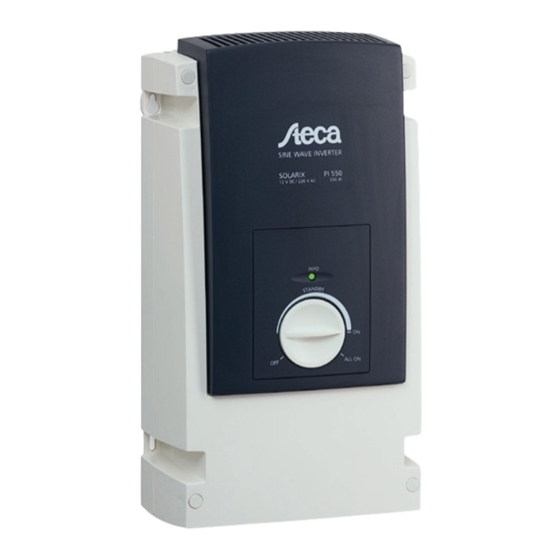
    Beschreibung 3.1 Aufbau Der Wechselrichter besteht aus folgenden Komponenten: 1 Drehschalter zum Ein-/Ausschalten und zur Einstellung des Einschaltpegels (siehe Kapitel 5.2). 2 LED zur Signalisierung der Betriebszustände 3 Batteriekabel: rot = +, ca. 1,5 m lang 4 Batteriekabel: schwarz = –, ca. 1,5 m lang 5 Netzkabel, 3-adrig, ca.
  • Seite 7: Installation

    Installation Fuse Netz 4.1 Montage 4.1.1 Montageort 190,23 Sicherstellen, dass der Montageort folgende Anforderungen erfüllt: • Montage in einem trockenen und staubfreien Innenraum. • Montage auf ebenem Untergrund. Fuse Netz • Montage an der Wand, auf Beton oder einer anderen nicht brennbaren Ober- Fuse Netz fläche in aufrechter Stellung.
  • Seite 8: Anschließen

    150 A träge oder 175 A flink wählen (60.000 ≤ I²t ≤ 200.000). Detaillierte Angaben und Dimensionierhilfen finden Sie im technischen Handbuch unter www.steca.com. Rotes Batteriekabel am Pluspol + der Batterie anklemmen. Schwarzes Batteriekabel am Minuspol – der Batterie anklemmen.
  • Seite 9: Betrieb

    Betrieb Die Wechselrichter sind mit einem Standby-System ausgerüstet. Um die Batterie nicht unnötig zu entladen, schaltet sich der Wechselrichter in diesem Betriebs- modus automatisch aus, wenn kein Verbraucher angeschlossen ist, und automa- tisch wieder ein, wenn ein Verbraucher eingeschaltet wird. Der Einschaltpegel (siehe Kapitel 5.2) wird mit dem Drehschalter eingestellt.
  • Seite 10: Hinweise Zum Betrieb

    5.2.2 Einschaltpegel so einstellen, dass kleine Verbraucher nicht erkannt werden Alle Verbraucher ausschalten und Drehschalter in die Stellung „Standby links“ drehen. Die LED blinkt grün.  Verbraucher, der nicht erkannt werden soll, einschalten und Drehschalter so weit im Uhrzeigersinn drehen, bis die LED dauerhaft leuchtet. In dieser Stellung wird der nicht gewünschte Verbraucher gerade er- ...
  • Seite 11: Pflege, Wartung Und Service

    42 V … 64 V Wiedereinschalt spannung (LVR) 12,5 V 25 V 25 V 50 V Tiefentladeschutz (LVD) stromgeführt oder über Steca Power Tarom AC-Ausgangsseite Ausgangsspannung 230 V AC 115 V AC 230 V AC 115 V AC 230 V AC...
  • Seite 12: Erweiterungsmöglichkeiten

    7.2 Erweiterungsmöglichkeiten Bis zu 4 Steca PI Wechselrichter können über eine Parallelschaltbox bei Erwei- terung der Anlage – oder wenn weitere Verbraucher hinzukommen – parallel geschaltet werden. Außerdem ist über die Parallelschaltbox die Kommunikation zu den Ladereglern Steca Tarom bzw. Steca Power Tarom möglich. Damit kann das PV-System SOC- gesteuert (State of Charge) betrieben werden.
  • Seite 13: Gewährleistung

    Gewährleistung Auf dieses Produkt hat der Kunde entsprechend den gesetzlichen Regelungen 2 Jahre Gewährleistung. Der Verkäufer wird sämtliche Fabrikations- und Materialfehler, die sich am Pro- dukt während der Gewährleistungszeit zeigen und die Funktionsfähigkeit des Produktes beeinträchtigen, beseitigen. Natürliche Abnutzung stellt keinen Fehler dar.
  • Seite 14: Kontakt

    10 Kontakt Bei Reklamationen und Störungen bitten wir Sie, sich mit Ihrem lokalen Händler in Verbindung zu setzen, bei dem Sie das Produkt gekauft haben. Dieser wird Ihnen in allen Belangen weiterhelfen. Steca Elektronik GmbH Mammostraße 1 87700 Memmingen Germany...
  • Seite 15: Index

    Index Introduction ....................16 About this manual ..................17 Applicability ..................17 Users ....................17 Description of symbols ............... 17 Safety ......................18 Proper usage ..................18 Improper usage ................. 18 Other risks ..................18 Fault behaviour .................. 18 Exclusion of liability ................18 Description ....................19 Construction ..................
  • Seite 16: Introduction

    Introduction The Steca Solarix PI 550, PI 600, PI 1100 and PI 1200 are stand-alone inverters for PV battery systems. They convert the battery’s DC voltage into sinusoidal AC voltage. This makes it possible to use any normal AC appliances that are in a suitable performance class.
  • Seite 17: About This Manual

    About this manual These operating instructions are part of the product. Read these operating instructions carefully before use, keep them over the entire lifetime of the product, and pass them on to any future owner or user of this product. 1.1 Applicability This manual describes the installation, function, operation and maintenance of the stand-alone inverters.
  • Seite 18: Safety

    Safety 2.1 Proper usage The inverters are exclusively intended for use in stationary autonomous power supplies in accordance with these operating instructions. Any other use is regarded as improper use of the device. 2.2 Improper usage • The inverter must never be connected to the public mains grid or a generator. •...
  • Seite 19: Description

    Description 3.1 Construction The inverter consists of the following components: 1 Rotary switch for switching on/off and setting the switch-on threshold (see chapter 5.2). 2 LED for indicating the operating modes 3 Battery cable: red = +, approx. 1.5 m long 4 Battery cable: black = –, approx.
  • Seite 20: Installation

    Installation Fuse Netz 4.1 Mounting 4.1.1 Mounting location 190,23 Ensure that the mounting location satisfies the following requirements: • Mount in a dry, dust-free indoor room. • Mount on even surface. • Mount upright on the wall, on concrete or on any other non-flammable Fuse Netz Fuse...
  • Seite 21: Connection

    150 A slow blow or 175 A fast blow (60,000 ≤ I²t ≤ 200,000). For detailed information and help in sizing see the technical manual at www.steca.com. Connect the red battery cable to the positive terminal + of the battery.
  • Seite 22: Operation

    Operation The inverters are equipped with a standby system. To avoid unnecessarily discharging the battery, in this operating mode the inverter switches off auto- matically when no consumer device is connected and switches on automatically when a consumer device is switched on. The switch-on threshold (see chapter 5.2) is set via the rotary switch.
  • Seite 23: Notes On Operation

    5.3 Notes on operation Switch-on delays When operating in the “Standby” setting, small delays may occur when consum- er devices are switched on. These delays are design-related and do not signify a fault. Noise emission • The inverter has a fan that automatically switches on when the device heats up, e.g.
  • Seite 24: Care, Maintenance And Service

    42 V … 64 V Reconnection voltage (LVR) 12,5 V 25 V 25 V 50 V Deep discharge protection (LVD) current driven or by Steca Power Tarom AC output side Output voltage 230 V AC 115 V AC 230 V AC 115 V AC...
  • Seite 25: Expansion Possibilities

    7.2 Expansion possibilities Up to 4 Steca PI inverters can be connected in parallel via a parallel switch box when the system is extended or when additional consumer devices are connected. The parallel switch box also allows communication with Steca Tarom or Steca Power Tarom charge controllers.
  • Seite 26: Legal Guarantee

    Legal guarantee In accordance with German statutory regulations, there is a 2-year legal guaran- tee on this product for the customer. The seller will remove all manufacturing and material faults that occur in the product during the guarantee period and affect the correct functioning of the product.
  • Seite 27: Contact

    10 Contact In the case of complaints or faults, we request that you contact the local supplier from whom you purchased the product. They will help you with any issues you may have. Steca Elektronik GmbH Mammostrasse 1 87700 Memmingen Germany...
  • Seite 28: El Índice

    El índice Introducción ....................29 Acerca de estas instrucciones ..............30 Validez ....................30 Destinatarios ..................30 Aclaración de símbolos ..............30 Seguridad ....................31 Empleo previsto ................. 31 Empleo inadmisible ................31 Riesgos restantes ................31 Comportamiento en caso de averías ..........31 Exención de responsabilidad ..............
  • Seite 29: Introducción

    Introducción Steca Solarix PI 550, PI 600, PI 1100 y PI 1200 son inversores aislados para sistemas fotovoltaicos de batería que transforman la corriente continua de la batería en corriente alterna senoidal. Esto permite usar cualquier consumidor de corriente alterna común de la correspondiente clase de potencia, tales como he- rramientas, equipos de audio y vídeo para el hogar, electrodomésticos, lámparas,...
  • Seite 30: Acerca De Estas Instrucciones

    Acerca de estas instrucciones Estas instrucciones de manejo son parte del producto. Leer detenidamente las instrucciones de manejo antes de usar, conservarlas durante toda la vida útil del producto, entregarlas a todos los propietarios o usuarios sucesivos del producto. 1.1 Validez Estas instrucciones describen la instalación, la función, el manejo y el manteni- miento de los inversores aislados.
  • Seite 31: Seguridad

    Seguridad 2.1 Empleo previsto Los inversores han sido exclusivamente concebidos para ser utilizados en fuentes de suministro de corriente estacionarias y autónomas según estas instrucciones de manejo. Cualquier otro uso diferente a ése o que lo supere no se considerará conforme a lo previsto.
  • Seite 32: Descripción

    Descripción 3.1 Estructura El inversor consta de los siguientes componentes: 1 Interruptor giratorio para la conexión/desconexión y para el ajuste del nivel de encendido (véase capítulo 5.2). 2 LED para indicar los estados de funcionamiento 3 Cable de la batería: rojo = +, aprox. 1,5 m de largo 4 Cable de la batería: negro = –, aprox.
  • Seite 33: Instalación

    Instalación Fuse Netz 4.1 Montaje 4.1.1 Lugar de montaje Asegurarse de que el lugar de montaje cumple con los siguientes requisitos: 190,23 • Montaje en un lugar interior seco y sin polvo. • Montaje sobre una base recta. Fuse Netz •...
  • Seite 34: Conexión

    30 V y una función de corte de como mínimo 150 A (lenta) o 175 A (rápida) (60.000 ≤ I²t ≤ 200.000). En el manual técnico que se encuentra en www.steca.com aparecen todos los datos detallados y las ayudas para el dimensionamiento.
  • Seite 35: Operación

    Operación El inversor está equipado con un sistema standby. Para no descargar la bate- ría innecesariamente, el inversor se apaga automáticamente en este modo de funcionamiento cuando no hay consumidores conectados y se vuelve a encender automáticamente cuando se conecta un consumidor. El nivel de encendido (véa- se capítulo 5.2) se ajusta con el interruptor giratorio.
  • Seite 36: Indicaciones Para El Funcionamiento

    5.2.2 Ajustar el nivel de encendido de manera que los consumidores pe- queños no se detecten Desconectar todos los consumidores y girar el interruptor hacia la posición "Standby izquierda". El LED parpadeará de color verde.  Conectar el consumidor que no debe ser detectado y girar el interruptor en el sentido de las agujas del reloj hasta que el LED se encienda de forma permanente.
  • Seite 37: Cuidado, Mantenimiento Y Servicio

    Tensión de reconexión (LVR) 12,5 V 25 V 25 V 50 V Protección contra descarga profunda por corriente o por Steca Power Tarom (LVD) Datos de salida CA Tensión de salida 230 V AC 115 V AC 230 V AC...
  • Seite 38: Posibilidades De Ampliación

    7.2 Posibilidades de ampliación Pueden conectarse en paralelo hasta 4 inversores Steca PI a través de una caja de conexiones en paralelo para ampliar la instalación o si se añade otros consumi- dores. Además, es posible la comunicación con los reguladores de carga Steca Tarom y Steca Power Tarom a través de la caja de conexiones en paralelo.
  • Seite 39: Garantía Legal

    Garantía legal De conformidad con las regulaciones legales alemanas, el cliente tiene sobre este producto una garantía legal de 2 años. El vendedor reparará todos los defectos de fabricación y de material que se manifiesten en el producto durante el tiempo de garantía legal y que afecten el funcionamiento del mismo.
  • Seite 40: Contacto

    10 Contacto En caso de reclamaciones y averías, le rogamos ponerse en contacto con el distribuidor local al que ha adquirido el producto. Éste le ayudará en todo lo que pueda. Steca Elektronik GmbH Mammostrasse 1 87700 Memmingen Alemania +49 8331 8558-833 +49 8331 8558-132 Correo electrónico...
  • Seite 41: Sommaire

    Sommaire Introduction ....................42 À propos de ce manuel d‘utilisation............43 Validité....................43 Groupe cible ..................43 Explication des symboles ..............43 Sécurité ....................44 Utilisation conforme ................44 Utilisation non conforme ..............44 Risques résiduels ................44 Comportement à adopter en cas de dysfonctionnements ....44 Exclusion de la responsabilité...
  • Seite 42: Introduction

    Introduction Steca Solarix PI 550, PI 600, PI 1100 et PI 1200 sont des onduleurs à fonctionne- ment en îlotage destinés aux systèmes de batteries PV. Ils convertissent la tension continue de la batterie en une tension alternative sinusoïdale. Cela permet l’uti- lisation de tous les consommateurs de courant alternatif usuels de la catégorie...
  • Seite 43: Propos De Ce Manuel D'utilisation

    À propos de ce manuel d'utilisation Ce manuel d'utilisation fait partie intégrante du produit. Veuillez lire attentivement le manuel avant utilisation, conservez-le pendant la durée de vie du produit, et transmettez-le à tout détenteur ou utilisateur ultérieur. 1.1 Validité Ces instructions décrivent l’installation, le fonctionnement, l’utilisation et la maintenance des onduleurs à...
  • Seite 44: Sécurité

    Sécurité 2.1 Utilisation conforme Les onduleurs sont uniquement conçus pour être utilisés dans les systèmes d’ali- mentation électrique stationnaires et autonomes, conformément aux instruc- tions figurant dans ce manuel d’utilisation. Toute autre utilisation ou utilisation sortant de ce cadre est considérée comme non conforme.
  • Seite 45: Description

    Description 3.1 Conception L’onduleur est constitué des composants suivants : 1 Commutateur rotatif pour la mise en marche/à l’arrêt et pour le réglage du niveau d’enclenchement (voir chapitre 5.2). 2 DEL de signalisation des états de fonctionnement 3 Câble de batterie : rouge = +, env. 1,5 m de long 4 Câble de batterie : noir = -, env.
  • Seite 46: Installation

    Installation Fuse Netz 4.1 Montage 4.1.1 Lieu de montage 190,23 Veillez à ce que le lieu de montage remplisse les conditions suivantes : • Montage dans un local sec et exempt de poussières. • Montage sur un sol plan. • Montage au mur, sur du béton ou une autre surface non inflammable en posi- Fuse Netz Fuse...
  • Seite 47: Raccordement

    175 A en cas d’action instantanée (60 000 ≤ I²t ≤ 200 000). Vous trouverez des données détaillées et des aides au dimensionnement dans le manuel technique sous www.steca.com. Raccordez le câble de batterie rouge au pôle positif + de la batterie.
  • Seite 48: Fonctionnement

    Fonctionnement Les onduleurs sont équipés d’un système de veille. Pour ne pas décharger inuti- lement la batterie, l’onduleur se déconnecte automatiquement dans ce mode de fonctionnement si aucun consommateur n'est raccordé, et se réactive automati- quement lorsqu'un consommateur est raccordé. Le niveau d’enclenchement (voir chapitre 5.2) peut être réglé...
  • Seite 49: Remarques Concernant Le Fonctionnement

    5.2.2 Réglage du niveau d’enclenchement de sorte que les petits consom- mateurs ne soient pas reconnus Désactivez tous les consommateurs et tournez le commutateur rotatif en position « Standby gauche ». La DEL verte clignote.  Activez le consommateur ne devant pas être reconnu et tournez le commu- tateur rotatif dans le sens des aiguilles d’une montre jusqu’à...
  • Seite 50: Entretien, Maintenance Et Service

    12,5 V 25 V 25 V 50 V ment (LVR) Protection contre la decharge pro- par régulation de courant ou par Steca Power Tarom fonde (LVD) Côté sortie AC Tension du réseau 230 V AC 115 V AC 230 V AC...
  • Seite 51: Possiblités D'extension

    7.2 Possiblités d’extension Jusqu’à 4 onduleurs Steca PI peuvent être branchés en parallèle via un boîtier de montage en parallèle en cas d’extension de l’installation – ou en cas de rajout de nouveaux consommateurs. De plus, le boîtier de montage en parallèle permet la communication avec les régulateurs de charge Steca Tarom ou Steca Power Tarom.
  • Seite 52: Garantie Légale

    Garantie légale En vertu des dispositions législatives allemandes en vigueur, le client bénéficie d'une garantie légale de 2 ans sur ce produit. Le vendeur est tenu de remédier à tous vices de fabrication et de matériau surve- nant pendant la période de garantie légale et entravant le bon fonctionnement du produit.
  • Seite 53: Contact

    10 Contact En cas de réclamations et de dysfonctionnements, veuillez contacter le revendeur chez qui vous avez acheté le produit. Il vous aidera dans toutes vos démarches. Steca Elektronik GmbH Mammostrasse 1 87700 Memmingen Allemagne +49 8331 8558-833 +49 8331 8558-132 E-mail service@stecasolar.com...
  • Seite 54: Indice

    Indice Introduzione ....................55 Note alle presenti istruzioni ..............56 Validità ....................56 Destinatari ..................56 Spiegazione dei simboli ..............56 Sicurezza ....................57 Utilizzo conforme ................57 Utilizzo non conforme ............... 57 Rischi residui ..................57 In caso di guasto ................57 Esclusione di responsabilità...
  • Seite 55: Introduzione

    Introduzione Steca Solarix PI 550, PI 600, PI 1100 e PI 1200 sono inverter per impianti ad isola per sistemi FV con batteria, che trasformano in tensione alternata sinusoidale la tensione continua della batteria. In questo modo si possono utilizzare tutte le usuali utenze in corrente alternata della rispettiva classe di potenza, come per es.
  • Seite 56: Note Alle Presenti Istruzioni

    Note alle presenti istruzioni Le presenti istruzioni d‘uso sono parte integrante del prodotto. Leggere attentamente le istruzioni prima dell‘uso, conservarle durante tutta la vita del prodotto, e consegnarle al successivo proprietario o utilizzatore del prodotto. 1.1 Validità Le presenti istruzioni illustrano installazione, funzionamento, uso e manutenzio- ne degli inverter per impianti ad isola.
  • Seite 57: Sicurezza

    Sicurezza 2.1 Utilizzo conforme Gli inverter devono essere utilizzati esclusivamente per l‘alimentazione elettrica stazionaria e autonoma di energia elettrica in base alle presenti istruzioni d‘uso. Ogni altro o ulteriore utilizzo dell’apparecchio deve essere considerato non conforme. 2.2 Utilizzo non conforme •...
  • Seite 58: Descrizione

    Descrizione 3.1 Struttura LL‘inverter è composto dai seguenti componenti: 1 Interruttore rotante per l‘inserzione/disinserzione e per l‘impostazione del picco di inserzione (vedere capitolo 5.2) 2 LED per la segnalazione delle condizioni di funzionamento 3 Cavo batteria: rosso = +, lunghezza 1,5 m circa 4 Cavo batteria: nero = –, lunghezza 1,5 m circa 5 Cavo di rete, 3 fili, lunghezza 1,5 m circa cavo batteria: nero = –, lunghezza 1,5 m circa...
  • Seite 59: Installazione

    Installazione Fuse Netz 4.1 Montaggio 4.1.1 Posizione di montaggio 190,23 Assicurarsi che la posizione di montaggio soddisfi i seguenti requisiti: • Montaggio in un locale asciutto e privo di polvere. • Montaggio su sottofondo piano. Fuse Netz • Montaggio a parete, su calcestruzzo o su un‘altra superficie ignifuga in posi- Fuse Netz zione diritta.
  • Seite 60: Collegamento

    V e una funzione di disinserzione minima di 150 A ritardata o 175 A rapida (60.000 ≤ l²t ≤ 200.000). Per dati dettagliati e ausili per il dimensionamen- to consultare il manuale tecnico sul sito www.steca.com. Collegare il cavo batteria rosso al polo positivo + della batteria.
  • Seite 61: Funzionamento

    Funzionamento Gli inverter sono dotati di un sistema di standby. Per non scaricare inutilmente la batteria, in questo modo operativo l‘inverter si disinserisce automaticamente quando non ci sono utenze collegate e si inserisce automaticamente quando viene collegata un‘utenza. Il picco di inserzione (vedere capitolo 5.2) viene impo- stato tramite l’interruttore rotante.
  • Seite 62: Consigli Per L'uso

    5.2.2 Impostare il picco di inserzione in modo che le utenze piccole non vengano riconosciute Disinserire tutte le utenze e ruotare l’interruttore rotante in posizione „Standby sinistra“. Il LED verde lampeggia.  Inserire l‘utenza che non deve essere riconosciuta e ruotare l’interruttore rotante in senso orario finché...
  • Seite 63: Cura, Manutenzione E Assistenza

    Tensione di ripristino (LVR) 12,5 V 25 V 25 V 50 V Protezione da scarica profonda (LVD) controllato in funzione della corrente o tramite Steca Power Tarom Lato uscita CA Tensione di uscita 230 V AC 115 V AC 230 V AC...
  • Seite 64: Possibilità Di Espansione

    Tramite la stessa scatola si può inoltre stabilire la comunicazione con i regolatori di carica Steca Tarom o Steca Power Tarom. In tal modo è possibile il funziona- mento del sistema FV a comando SOC (State of Charge). Vedere a questo proposito le istruzioni d‘uso della scatola per collegamento in parallelo specifiche per PAx4.
  • Seite 65: Garanzia Legale

    Garanzia legale La garanzia legale riconosciuta al cliente su questo prodotto ha una durata di due anni, come previsto dalle disposizioni legislative tedesche. Il rivenditore provvederà a riparare tutti i guasti e le anomalie imputabili ad er- rori di fabbricazione e materiale che dovessero presentarsi sul prodotto durante il periodo di garanzia legale, pregiudicando la funzionalità...
  • Seite 66: Contatto

    10 Contatto In caso di reclami o guasti si prega di rivolgersi al rivenditore presso il quale è stato acquistato l’apparecchio, dove verrà fornita un’assistenza completa. Steca Elektronik GmbH Mammostrasse 1 87700 Memmingen Allemagne +49 8331 8558-833 +49 8331 8558-132 E-mail service@stecasolar.com...
  • Seite 67 746.489 | 12.41...
  • Seite 68 746.489 | 12.41...
  • Seite 69 746.489 | 12.41...
  • Seite 70 746.489 | 12.41...
  • Seite 71 746.489 | 12.41...
  • Seite 72 746489 746.489 | 12.41...

Inhaltsverzeichnis