
Verwandte Anleitungen für urmet sinthesi S2 2VOICE 1083


Inhaltszusammenfassung für urmet sinthesi S2 2VOICE 1083
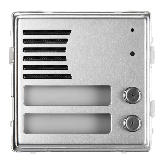
- Seite 1 Mod. 1083 DS 1083-056B LBT 20048 POSTO ESTERNO AUDIO SINTHESI SINTHESI AUDIO ENTRY PANEL POSTE EXTERNE AUDIO SINTHESI MICROALTAVOZ AUDIO SINTHESI AUDIO-AUSSENSTELLE SINTHESI Sch./Ref. 1083/74...
- Seite 2 ITALIANO Il posto esterno Sch. 1083/74 è dedicato al sistema 2Voice. È realizzato su meccanica Sinthesi S2 a 1 modulo e prevede 2 tasti di chiamata. INSTALLAZIONE PULSANTIERA Installare il modulo all’altezza indicata. Montare il telaio portamoduli sulla scatola incasso. Montare i moduli sul telaio.
- Seite 3 (*) Nel caso di persone con disabilità o specifi che necessità di tipo D1 (con età avanzata) e D2 (con diffi coltà motoria degli arti inferiori), il centro del dispositivo dovrà essere posizionato ad una altezza compresa tra 75 cm e 140 cm rispetto al piano di calpestio. Per ulteriori dettagli vedere la Norma tecnica CEI 64-21:2016- 12 - Ambienti residenziali.
- Seite 4 Lato incisione ROSSI ROSSI Cartellino bianco DS1083-056B...
- Seite 5 • Posizionare la cornice sul telaio. • Serrare le viti B sulle viti A. DS1083-056B...
- Seite 6 DESCRIZIONE DEI MORSETTI, DEI CONNETTORI E DEI JUMPER Azionamento elettroserratura passo carraio Pulsante androne Pulsante androne Sensore porta aperta Sensore porta aperta Non utilizzato Non utilizzato Alimentazione per illuminazione cartellini LINE Linea Bus entrante Negativo azionamento elettroserratura pedonale Positivo azionamento elettroserratura pedonale VIDEO IN Connettore per modulo telecamera Sch.
- Seite 7 CONFIGURAZIONE DEI POSTI ESTERNI CONV DOOR TIME TIME Valori di default: tutti i posti esterni escono di fabbrica confi gurati nel seguente modo: Tipo PE: principale Numero secondario: Apriporta: libero Interruzione: Non garantita Rotary tempo comunicazione garantita: 30 s (pos 3) Rotary apriporta: 1 s (pos 0) Numero posto esterno:...
- Seite 8 ID=0 ID=1 ID=2 ID=3 ID=4 ID=5 ID=6 ID=7 ID=8 ID=9 ID=10 ID=11 ID=12 ID=13 ID=14 ID=15 ID=16 ID=17 ID=18 ID=19 ID=20 ID=21 ID=22 ID=23 ID=24 ID=25 ID=26 ID=27 ID=28 ID=29 ID=30 ID=31 AUX: impostazioni ausiliarie Tipo di postazione: il posto esterno può essere confi gurato come principale o come secondario. Dal posto esterno principale è...
- Seite 9 • ‘Libero’: la pressione del pulsante apriporta di un posto interno può attivare l’elettroserratura del posto esterno solo se il posto esterno è confi gurato come principale o l’utente appartiene alla colonna dello stesso posto esterno secondario. Tale colonna è defi nita dalla impostazione dell’ID del posto esterno secondario.
-
Seite 10: Configurazione Avanzata
TEMPO APRIPORTA La posizione del rotary switch (DOOR TIME) determina il tempo di tenuta dell’elettroserratura pedonale. Pos. 0 = 1 s Pos. 1 = 10 s Pos. 2 = 20 s Pos. 3 = 30 s Pos. 4 = 40 s Pos. - Seite 11 esterno sia confi gurato come secondario. Qualora invece il posto esterno sia confi gurato come principale, allora i tasti sono automaticamente associati alla colonna 0, il che semplifi ca l’installazione di principali su impianti monocolonna. P5÷P8 P5÷P8 P9÷P12 P9÷P12 1083/17 (1) 1083/17 (4) P1÷P4 P1÷P4...
- Seite 12 Esempio: La confi gurazione fi nale sarà la seguente: Inizio Inizio Inizio • Impianto con 3 colonne, la prima con 4 colonna 0 colonna 1 colonna 2 utenti, la seconda con 6 utenti, la terza con 8 utenti. 4 UTENTI 6 UTENTI 8 UTENTI •...
- Seite 13 Se i posti esterni sono confi gurati come secondari ma si vuole che ognuno chiami un diverso gruppo di utenti si può procedere nel seguente modo: • Accedere alla confi gurazione avanzata ruotando sulla posizione ‘99’ i due rotary switch (si accende il led giallo);...
- Seite 14 “B” Postazione di chiamata secondaria con 8 tasti ID = n AUX dip2 = 1 interfaccia offset = 11 di colonna Chiama gli utenti da 11 a 18 ID = n Postazione di chiamata secondaria con 11 tasti ID = n AUX dip2 = 0 offset = 0 Chiama gli utenti da 0 a 10...
- Seite 15 REGOLAZIONE FONIA I livelli fonici sono tarati di fabbrica in modo da non dover essere variati nella maggioranza delle installazioni. Qualora fosse necessario modifi carli, agire con un cacciavite sulle apposite regolazioni. Regolazione Regolazione volume volume altoparlante microfono AZIONAMENTO ELETTROSERRATURA PEDONALE I posti esterni hanno due morsetti per la gestione a scarica capacitiva dell’elettroserratura (SE-, SE+).
-
Seite 16: Caratteristiche Tecniche
AZIONAMENTO ELETTROSERRATURA PASSO CARRAIO I posti esterni hanno due morsetti connessi ai contatti di un relè normalmente aperto, utilizzabile come comando di una centralina apricancello (1). Il relè viene pilotato per 1 secondo alla ricezione del comando apriporta passo carraio di un posto interno in funzione della confi gurazione della modalità di funzionamento ‘libero’... -
Seite 17: Panel Installation
ENGLISH The door unit Ref. 1083/74 is dedicated to Voice system. It consists of a one module Sinthesi S2 unit with two calling buttons. PANEL INSTALLATION Install the module at the height shown. Fit the module holder frame in the fl ush-mounting box. Fit the modules in the frame. - Seite 18 Fasten the screws A DS1083-056B...
- Seite 19 Engraving side ROSSI ROSSI Blank tag DS1083-056B...
- Seite 20 • Position the panel on the frame. • Fasten screws B and screws A. DS1083-056B...
- Seite 21 DESCRIPTION OF TERMINALS, CONNECTORS AND JUMPERS Driveway electric lock activation Hall button Hall button Open door detector Open door detector Not used Not used Power supply for name tags lighting LINE Bus line in Negative for pedestrian crossing electric lock Positive for pedestrian crossing electric lock VIDEO IN Connector for camera module Ref.
- Seite 22 DOOR UNITS CONFIGURATION CONV DOOR TIME TIME Default settings: default indoor station settings are: PE type: main Secondary number: Door opener: free Interruption: Not assured Guaranteed conversation time rotary: 30 s (pos 3) Door lock release rotary: 1 s (pos 0) Door unit number: Camera LED on (if connected): door unit number...
- Seite 23 ID=0 ID=1 ID=2 ID=3 ID=4 ID=5 ID=6 ID=7 ID=8 ID=9 ID=10 ID=11 ID=12 ID=13 ID=14 ID=15 ID=16 ID=17 ID=18 ID=19 ID=20 ID=21 ID=22 ID=23 ID=24 ID=25 ID=26 ID=27 ID=28 ID=29 ID=30 ID=31 AUX: auxiliary settings Station type: the door unit can be confi gured either as a main or a secondary device. All the users in the system may be called from the main door unit.
- Seite 24 • ‘Free’: when pressing the door lock release button of an apartment station, the door unit electric lock can be activated only if the door unit is confi gured as main or the user belongs to the column of the same secondary door unit.
-
Seite 25: Advanced Configuration
DOOR OPENING TIME The position of the rotary switch (DOOR TIME) determines the activation time of the door lock. Pos. 0 = 1 s Pos. 1 = 10 s Pos. 2 = 20 s Pos. 3 = 30 s Pos. 4 = 40 s Pos. - Seite 26 If instead the door unit is confi gured as main unit, then the buttons are automatically associated to the column 0, which simplifi es the installation of main units in single column systems. P5÷P8 P5÷P8 P9÷P12 P9÷P12 1083/17 (1) 1083/17 (4) P1÷P4 P1÷P4 P13÷P16...
- Seite 27 Example: The fi nal confi guration will be: Column Column Column • System with 3 columns, the fi rst with 4 0 start 1 start 2 start users, the second with 6 users and the third with 8 users. 4 USERS 6 USERS 8 USERS •...
- Seite 28 If the door units are confi gured as secondary, but each one must call a different group of users, the following steps can be performed: • Access to advanced confi guration by setting both the two rotary dip-switches to position ‘9’ (the yellow led turns on);...
- Seite 29 “B” Secondary call module with 8 buttons ID = n AUX dip 2 = 1 column offset = 11 interface Called users: from 11 to 18 ID = n Secondary call module with 11 buttons ID = n AUX dip 2 = 0 offset = 0 Called users: from 0 to 10 2Voice...
- Seite 30 AUDIO ADJUSTING The audio levels are trimmed in factory, so they don’t need to be changed in most installations. If it is necessary to change them, use a screwdriver on the suitable adjusting points. Speaker Microphone volume volume adjustment adjustment DOOR ELECTRIC LOCK MANAGEMENT The door units have two terminals for managing the capacitance discharge and hold of the door electric lock (SE-, SE+).
-
Seite 31: Accessories
GARAGE DOOR LOCK MANAGEMENT The doors have two terminals connected to the contacts of a normally open relay which can be used to control a gate opening control unit (1). The relay is operated for 1 second after receiving the garage door opening command according to the operating mode (“free”... - Seite 32 FRANÇAIS Le poste externe Réf. 1083/74 a été projeté exprès pour le système 2Voice. Il est réalisé à partir d’une Sinthesi S2 à un module et comporte deux touches d’appel. INSTALLATION DU CLAVIER Installer le module à la hauteur indiquée. Installer le châssis porte-modules sur le boîtier à...
- Seite 33 (*) Respecter une hauteur de pose de 1,30 m pour se conformer à la Directive de référence pour les personnes handicapées (par exemple,en France, voir la Loi 2005-102 du 11/02/2005, le Décret 2006- 555 du 17/05/2006 et ses amendements ultérieurs des 1/08/2006,26/02/2007 et 21/03/2007). Visser les vis A DS1083-056B...
- Seite 34 Côté entaille ROSSI ROSSI Etiquette blanche DS1083-056B...
- Seite 35 • Positionner l’habillage sur le châssis. • Serrer les vis B sur les vis A. DS1083-056B...
- Seite 36 DESCRIPTION DES BORNES, DES CONNECTEURS ET DES CAVALIERS Actionnement de la serrure électrique pour la sortie des voitures Bouton hall d’entrée Bouton hall d’entrée Senseur porte ouverte Senseur porte ouverte Non utilisé Non utilisé Alimentation pour l’éclairage des étiquettes LINE Ligne Bus entrante Négatif d’actionnement de la serrure électrique pour passage piéton Positif d’actionnement de la serrure électrique pour passage piéton VIDEO IN Connecteur pour module caméra Réf.
- Seite 37 CONFIGURATION DES POSTES EXTERNES CONV DOOR TIME TIME Valeurs implicites: tous les postes externes sont confi gurés en usine de la façon suivante: Type PE: principal Numéro secondaire: Ouvre-porte: libre Interruption: non assurée Dip-switch rotatif temps de communication garantie: 30 s (pos 3) Dip-switch rotatif ouvre-porte: 1 s (pos 0) Numéro poste externe:...
- Seite 38 ID=0 ID=1 ID=2 ID=3 ID=4 ID=5 ID=6 ID=7 ID=8 ID=9 ID=10 ID=11 ID=12 ID=13 ID=14 ID=15 ID=16 ID=17 ID=18 ID=19 ID=20 ID=21 ID=22 ID=23 ID=24 ID=25 ID=26 ID=27 ID=28 ID=29 ID=30 ID=31 AUX: saisies auxiliaires Type de poste: le poste externe peut être confi guré en tant que principal ou secondaire. Du poste externe principale il est possible d’appeler tous les utilisateurs de l’installation, alors que du poste externe secondaire il est possible d’appeler les utilisateurs de la colonne d’appartenance uniquement.
- Seite 39 • “Libre“: l’actionnement de la touche ouvre-porte d’un poste interne peut activer la serrure électrique du poste externe si celui-ci est confi guré comme principal ou si l’utilisateur appartient à la colonne du même poste externe secondaire. La fonction est généralement utilisée sur les postes secondaires. Les informations reportées concernent aussi bien l’électro-serrure de l’accès véhicules que celle pour piétons.
-
Seite 40: Configuration Avancée
TEMPS OUVRE-PORTE La position de l’interrupteur rotatif (DOOR TIME) détermine le temps d’activation de la serrure électrique du passage pour piétons. Pos. 0 = 1 s Pos. 1 = 10 s Pos. 2 = 20 s Pos. 3 = 30 s Pos. - Seite 41 Par contre, si le poste externe est confi guré comme principal, alors les touches sont automatiquement associées à la colonne 0, ce qui simplifi e l’installation des postes principaux sur des installations à une seule colonne. P5÷P8 P5÷P8 P9÷P12 P9÷P12 1083/17 (1) 1083/17 (4) P1÷P4...
- Seite 42 • Repositionner les micro-interrupteurs ID La confi guration fi nale sera la suivante: sur la position d’origine. Début de Début de Début de • Quitter la confi guration avancée, reporter les colonne 1 colonne 2 colonne 0 deux interrupteurs rotatifs sur les positions de confi...
- Seite 43 Si les postes externes sont confi gurés comme secondaires, mais on veut que chacun appelle un groupe différent d’utilisateurs, on peut procéder de la façon suivante: • Accéder à la confi guration avancée en tournant tous les deux dip-switch rotatifs sur la position ‘9’ (la led jaune s’allume);...
- Seite 44 “B” Poste d’appel secondaire avec 8 touches ID = n AUX dip 2 = 1 Interface offset = 11 de colonne Appelle les utilisateurs à partir de 11 jusqu’à 18 ID = n Poste d’appel secondaire avec 11 touches ID = n AUX dip 2 = 0 offset = 0 Appelle les utilisateurs à...
- Seite 45 EFFACEMENT DES DONNÉES DE PROGRAMMATION Pour effacer toutes les données programmées dans la confi guration avancée, suivre le procédé suivant: • Accéder à la confi guration avancée. • Appuyer sur une touche quelconque pendant au moins 5 secondes. Le poste externe émet un premier signal après 3 secondes et un autre plus long 2 secondes après pour confi...
- Seite 46 ACTIONNEMENT DE LA SERRURE ELECTRIQUE DU PASSAGE PIÉTON Les postes externes disposent de deux bornes pour la gestion par décharge capacitive de la serrure électrique (SE-, SE+). La serrure électrique est pilotée dans les cas suivants: • Chaque fois que la touche du hall d’entrée est actionnée (bornes PA). •...
-
Seite 47: Caracteristiques Techniques
ACCESSOIRES Pièce détachée façade avec une touche pour poste externe audio Réf. 1083/107 CARACTERISTIQUES TECHNIQUES Tension d’alimentation continue (LINE): ..................36 – 48 V Absorption au repos: ........................45 mA max Absorption maximale (appel et étiquettes allumées): ..............250 mA max Éclairage des étiquettes: ........................32 max Sortie serrure SE+ et SE-: ..................22 –... -
Seite 48: Instalación Del Teclado
ESPAÑOL El microaltavoz Ref. 1083/74 es dedicado al sistema 2Voice. Fabricado con mecánica Sinthesi S2 de 1 módulo, para 2 pulsadores de llamada. INSTALACIÓN DEL TECLADO Instalar el módulo a la altura indicada. Montar el bastidor portamódulos en la caja para empotrar. Montar los módulos en el bastidor. - Seite 49 Ajustar los tornillos A DS1083-056B...
- Seite 50 Lado grabado ROSSI ROSSI Tarjeta blanca DS1083-056B...
- Seite 51 • Colocar el marco en el bastidor. • Ajustar los tornillos B en los tornillos A. DS1083-056B...
- Seite 52 DESCRIPCIÓN DE LOS BORNES, LOS CONECTORES Y LOS PUENTES Accionamiento cerradura eléctrica vado permanente Pulsador vestíbulo Pulsador vestíbulo Sensor puerta abierta Sensor puerta abierta No utilizado No utilizado Alimentación para iluminación etiquetas LINE Línea Bus de entrada Accionamiento negativo cerradura eléctrica peatonal Accionamiento positivo cerradura eléctrica peatonal VIDEO IN Conector para módulo cámara Ref.
- Seite 53 CONFIGURACIÓN DE LOS MICROALTAVOCES CONV DOOR TIME TIME Valores estándard: todos los microaltavoces salen de fábrica confi gurados en la siguiente manera: Tipo PE: principal Número secundario: Apertura puerta: libre Interrupción: No garantizada Giratorio tiempo de comunicación garantizado: 30 s (pos 3) Giratorio apertura puerta: 1 s (pos 0) Número microaltavoz:...
- Seite 54 ID=0 ID=1 ID=2 ID=3 ID=4 ID=5 ID=6 ID=7 ID=8 ID=9 ID=10 ID=11 ID=12 ID=13 ID=14 ID=15 ID=16 ID=17 ID=18 ID=19 ID=20 ID=21 ID=22 ID=23 ID=24 ID=25 ID=26 ID=27 ID=28 ID=29 ID=30 ID=31 AUX: confi guraciones auxiliares Tipo de puesto: el microaltavoz se puede confi gurar como principal o como secundario. Desde el microaltavoz principal es posible llamar a todos los usuarios del sistema;...
- Seite 55 • Libre”: el accionamiento del pulsador de apertura de la puerta de un aparato interior puede activar la cerradura eléctrica del microaltavoz, si el mismo está confi gurado como principal, o si está confi gurado como secundario y el usuario pertenece a la misma columna del microaltavoz secundario. La función normalmente se utiliza en los puestos secundarios.
-
Seite 56: Configuración Avanzada
TIEMPO DE APERTURA DE LA PUERTA La posición del interruptor giratorio (DOOR TIME) determina el tiempo de activación de la cerradura eléctrica para peatones. Pos. 0 = 1 s Pos. 1 = 10 s Pos. 2 = 20 s Pos. 3 = 30 s Pos. - Seite 57 pertenecen, en el caso de un microaltavoz confi gurado como secundario. En cambio, si el microaltavoz está confi gurado como principal, los pulsadores se asocian automáticamente a la columna 0, lo que facilita la instalación de principales en sistemas monocolumna. P5÷P8 P5÷P8 P9÷P12...
- Seite 58 posiciones de confi guración del tiempo La confi guración fi nal será la siguiente: de apertura de la puerta y del tiempo de Inicio Inicio Inicio comunicación garantizado: el led amarillo columna 1 columna 2 columna 0 se apaga. 4 USUARIOS 6 USUARIOS 8 USUARIOS Ejemplo:...
- Seite 59 Si los microaltavoces son confi gurados como secundarios pero se desea que cada uno llame hacia un diferente grupo de usuarios se puede continuar en el siguiente modo: • Entrar en la confi guración de avance girando en la posición ‘99’ ambos los interruptores giratorios (se enciende el led amarillo);...
- Seite 60 “B” Puesto de llamada secundario con 8 teclas ID = n AUX dip 2 = 1 Interfaz offset = 11 de columna Llama los usuarios desde 11 hasta 18 ID = n Puesto de llamada secundario con 11 teclas ID = n AUX dip 2 = 0 offset = 0 Llama los usuarios desde 0 hasta 10...
- Seite 61 REGULACIÓN FONÍA Los niveles fónicos son programados en su producción en manera que no necesiten ser cambiados en la mayor parte de las instalaciones. En caso sea necesario cambiarlos, corregir con un tornillo en la regulación deseada. Regulación Regulación volumen volumen altavoz micrófono...
-
Seite 62: Caracteristicas Tecnicas
ACCIONAMIENTO CERRADURA ELÉCTRICA VADO PERMANENTE Los microaltavoces tienen dos bornes conectados con los contactos de un relé normalmente abierto, que se utiliza como mando de una centralita para el dispositivo de apertura del portón (1). Cuando se recibe el mando de apertura de la puerta del pasaje de vehículos desde un aparato interior, el relé se controla durante 1 s, según la confi... -
Seite 63: Installation Des Tastenfelds
DEUTSCH Die Außenstelle BN 1083/74 ist dem System 2Voice gewidmet. Sie ist auf Sinthesi S2-Mechanik mit 1 Modul eingerichtet und sieht 2 Ruftasten vor. INSTALLATION DES TASTENFELDS Das Modul auf der angegebenen Höhe installieren. Den Modulhalterrahmen auf das Einbaugehäuse montieren. Die Module auf den Rahmen montieren. - Seite 64 Schrauben A anziehen DS1083-056B...
- Seite 65 Gravurseite ROSSI ROSSI Weißes Schild DS1083-056B...
- Seite 66 • Den Einsatz auf dem Rahmen montieren. • Die Schrauben B auf den Schrauben A anziehen. DS1083-056B...
-
Seite 67: Beschreibung Der Klemmen, Der Verbinder Und Der Jumper
BESCHREIBUNG DER KLEMMEN, DER VERBINDER UND DER JUMPER Bedienung der Elektroverriegelung der Einfahrt für Autos Hausfl urtaste Hausfl urtaste Sensor Tür offen Sensor Tür offen Nicht verwendet Nicht verwendet Speisegerät für die Namensschildbeleuchtung LINE Eingehende BUS-Leitung Negativ Bedienung der Elektroverriegelung der Fußgänger-Eingang Positiv Bedienung der Elektroverriegelung der Fußgänger-Eingang VIDEO IN Verbinder für Kameramodul B/N 1748/83 Verbinder für Tastenerweiterungsmodul B/N 1083/17... -
Seite 68: Konfiguration Der Aussenstellen
KONFIGURATION DER AUSSENSTELLEN CONV DOOR TIME TIME Standardwerten: alle Außenstellen werden werkseitig konfi guriert, wie folgt: Typ PE (Außenstelle): Haupt Nebennummer: Türöffner: Frei Unterbrechung: Nicht gewährleistet DIP-Drehschalter garantierten Gesprächdauer: 30 s (pos 3) DIP-Drehschalter Türöffner: 1s (pos 0) Außenstellenummer: Einschalten der Kamera-Led (wenn angeschlossen): aktiviert Nummer der Außenstelle. - Seite 69 ID=0 ID=1 ID=2 ID=3 ID=4 ID=5 ID=6 ID=7 ID=8 ID=9 ID=10 ID=11 ID=12 ID=13 ID=14 ID=15 ID=16 ID=17 ID=18 ID=19 ID=20 ID=21 ID=22 ID=23 ID=24 ID=25 ID=26 ID=27 ID=28 ID=29 ID=30 ID=31 AUX: Nebeneinstellungen Art der Einheit: die Außenstelle kann als Haupt– oder Nebenstelle konfi guriert werden. Von der Hauptaußenstelle aus können alle Teilnehmer der Anlage angerufen werden.
- Seite 70 • ‚Frei’: das Betätigen der Türöffnertaste einer Innenstelle kann die Elektroverriegelung der Rufeinheit aktivieren, wenn diese als Haupteinheit konfi guriert ist oder wenn diese als Nebeneinheit konfi guriert ist und der Teilnehmer zu derselben Säule der Rufeinheit gehört. Diese Funktion wird normalerweise auf Nebenstellen eingesetzt.
-
Seite 71: Fortgeschrittene Konfiguration
DAUER TÜRÖFFNER Die Position des Drehschalters (DOOR TIME) bestimmt die Dauer der Aktivierung der Elektroverriegelung Eingang. Pos. 0 = 1 s Pos. 1 = 10 s Pos. 2 = 20 s Pos. 3 = 30 s Pos. 4 = 40 s Pos. - Seite 72 Sollte dagegen die Außenstelle als Haupteinheit konfi guriert sein, werden die Tasten automatisch mit der Steigleitung 0 assoziiert, was die Installation der Hauptstellen auf Anlagen mit nur einer Steigleitung erleichtert. P5÷P8 P5÷P8 P9÷P12 P9÷P12 1083/17 (1) 1083/17 (4) P1÷P4 P1÷P4 P13÷P16 P13÷P16 INPUT...
- Seite 73 gewünschten Türöffnerzeit Die Endkonfi guration ist folgende: garantierten Gesprächszeit bringen. Die Beginn Beginn Beginn gelbe Led erlischt. Steigleitung 1 Steigleitung 2 Steigleitung 0 Beispiel: 4 BENUTZER 6 BENUTZER 8 BENUTZER • Anlage mit drei Steigleitungen, die erste mit vier Teilnehmern, die zweite mit sechs Teilnehmern, die dritte mit acht Teilnehmern.
- Seite 74 Falls die Außenstellen als Nebenstellen konfi guriert sind, aber jede soll eine verschiedene Gruppe von Teilnehmern anrufen, kann man das unterliegende Verfahren folgen: • Um auf die fortgeschrittene Konfi guration zugreifen, beide DIP-Drehschalter in Position ‘9’ bringen (die gelbe LED schaltet sich ein); •...
-
Seite 75: Konfiguration Der Taste Für Spezialfunktion
“B” Nebenrufmodul mit 8 Tasten ID = n AUX dip 2 = 1 Schnittstelle offset = 11 der Steigleitung Er ruft die Teilnehmer von 11 bis 18 an ID = n Nebenrufmodul mit 11 Tasten ID = n AUX dip 2 = 0 offset = 0 Er ruft die Teilnehmer von 0 bis 10 an Netzteil... -
Seite 76: Audio-Einstellung
einen ersten Piepton aus und nach 2 Sekunden sendet sie einen anderen aber längeren Piepton zur Bestätigung der erfolgten Löschung aus. AUDIOEINSTELLUNG Die Audiostufen sind werkseitig eingestellt, damit sie in der meisten Anlagen nicht verändert werden müssen. Falls aber ihre Veränderung nötig wird, mit einem Schraubenzieher in den dafür vorgesehenen Reglerstellen wirken. - Seite 77 Konfi guration des Dip-Switch AUX, bezüglich auf “frei” oder “geheim” Betriebsmodus (siehe Abschnitt “Konfi guration”). Die Aktivierungszeit der Elektroverriegelung ist durch DIP-Drehschalter programmierbar. BETÄTIGUNG DER ELEKTROVERRIEGELUNG DER EINFAHRT FÜR AUTOS Die Außenstellen verfügen über zwei an die Kontakte eines Ruhekontakts angeschlossene Klemmen, die als Steuerung eines Steuergeräts zum Öffnen des Tors eingesetzt werden kann (1).
-
Seite 78: Technische Eigenschaften
TECHNISCHE EIGENSCHAFTEN Gleichspannungsversorgung (LINE): ..................... 36 – 48 V Stromentnahme bei Ruhestellung: ....................45 mA max Max. Stromaufnahme (Anlagenanruf und eingeschaltete Namensschilder): .........250 mA max Namenschildbeleuchtung: ........................32 max Ausgang Verriegelung SE+ und SE-: ...............22 – 24 V max 240 mA Betriebstemperatur: ........................-10 ÷... - Seite 79 ITALIANO DIRETTIVA 2012/19/UE DEL PARLAMENTO EUROPEO E DEL CONSIGLIO del 4 luglio 2012 sui rifi uti di apparecchiature elettriche ed elettroniche (RAEE) Il simbolo del cassonetto barrato riportato sull’apparecchiatura o sulla sua confezione indica che il prodotto alla fi ne della propria vita utile deve essere raccolto separatamente dagli altri rifi...
- Seite 80 Weise recycelt werden Weitere Informationen dazu, wo Sie Ihre Altgeräte zum Recycling abgeben können, erhalten Sie bei Ihrer Gemeindeverwaltung, Ihrem Hausmüll-Entsorgungsdienst oder bei dem Händler, bei dem Sie das Produkt gekauft haben. DS 1083-056B LBT 20048 URMET S.p.A. Area tecnica 10154 TORINO (ITALY) servizio clienti +39 011.23.39.810 VIA BOLOGNA 188/C http://www.urmet.com...