Inhaltsverzeichnis
Werbung
Verfügbare Sprachen
Verfügbare Sprachen
Quicklinks
English ······························································································· 3
Français ··························································································· 34
Deutsch ···························································································· 65
Español ···························································································· 96
Italiano ···························································································· 127
Nederlands ······················································································ 158
1
Werbung
Inhaltsverzeichnis

Verwandte Anleitungen für Siemens SITRANS TR Serie


Inhaltszusammenfassung für Siemens SITRANS TR Serie
- Seite 1 English ······························································································· 3 Français ··························································································· 34 Deutsch ···························································································· 65 Español ···························································································· 96 Italiano ···························································································· 127 Nederlands ······················································································ 158...
-
Seite 3: Legal Information
WARNING Siemens products may only be used for the applications described in the catalog and in the relevant technical documentation. If products and components from other manufacturers are used, these must be recommended or approved by Siemens. Proper transport, storage, installation, assembly, commissioning, operation and maintenance are required to ensure that the products operate safely and without any problems. - Seite 4 The contents of this manual shall not become part of or modify any prior or existing agreement, commitment or legal relationship. The sales contract contains all obligations on the part of Siemens as well as the complete and solely applicable warranty conditions.
-
Seite 5: Safety Notes
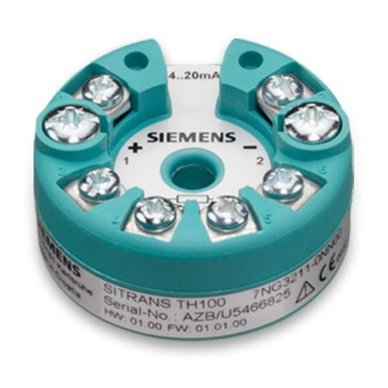
Nameplate structure ① ⑤ Version Ex marking with Ex data ② ⑥ Order number Electrical characteristics ③ ⑦ CE mark with ID number of Type of IP protection notified body ④ Serial number Safety notes This device left the factory in good working condition. In order to maintain this status and to ensure safe operation of the device, observe these instructions and all the specifications relevant to safety. - Seite 6 Symbol Meaning Pay attention to the operating instructions Observe the test certification, provisions and laws applicable in your country during connection, assembly and operation. These include, for example: ● National Electrical Code (NEC - NFPA 70) (USA) ● Canadian Electrical Code (CEC) (Canada) Further provisions for hazardous area applications are for example: ●...
-
Seite 7: Installation In The Connection Head
Mounting WARNING Exceeded maximum ambient or process media temperature Danger of explosion in hazardous areas. Device damage. ● Make sure that the maximum permissible ambient and process media temperatures of the device are not exceeded. Refer to the information in Chapter "Technical data (Page 26)". WARNING Open cable inlet or incorrect cable gland Danger of explosion in hazardous areas. - Seite 8 Securing the transmitter: in the connection head cover in the connection head base ① ② Transmitter Ceramic base of the measuring element ③ Connection head Note Using the lock washers (TH200/TH300 only) ④ ② The lock washers included in the delivery are only required for securely fastening the transmitter when the transmitter ③...
- Seite 9 Figure 3-1 Securing the transmitter on DIN rails Figure 3-2 Securing the transmitter on G rails 3.1.3 SITRANS TR installation on a DIN rail The transmitter is secured to a 35 mm DIN rail to DIN EN 60715. Comply with the ambient conditions specified in the technical data. SITRANS TH/TR/TF A5E32363963-01, 06/2013...
- Seite 10 Mounting SITRANS TF ① ⑥ Cover with inspection window Plug-in connector from SITRANS TH200 or TH300 ② ⑦ Display module (digital display) Ex nameplate ③ ⑧ Cable gland for auxiliary power M4 screw supply/analog output ④ ⑨ SITRANS TF field housing Cable gland for sensor cable ⑤...
- Seite 11 Note Reverse polarity protection The display module has integrated reverse polarity protection. The display module will not function if the polarity is reversed, but will not be damaged. Make sure the polarity is correct. If the display module does not function, reverse the polarity of the plug-in connector.
- Seite 12 Only intrinsically safe HART modems or HART communicators are allowed to be operated in the intrinsically safe area or on intrinsically safe circuits. Note Electrical data and T Electrical data and T are dependent on Ex-protection class, see Certificates (http://www.siemens.com/processinstrumentation/certificates) SITRANS TH/TR/TF A5E32363963-01, 06/2013...
- Seite 13 Safety notes for connecting in hazardous areas TH100 Zone 0, 1, 2 in type of protection "ia/ib/ic" - intrinsic safety ● Only connect the transmitter, in accordance with the certificate of compliance, to devices certified as intrinsically-safe. ● If the connection head is made of aluminum, the requirements of EN 60079-26, section 4.3.3, must be observed for uses where the device category 1 G is required.
-
Seite 14: Safety Notes For Connecting In Hazardous Th200
Safety notes for connecting in hazardous TH200/300 The 4 to 20 mA input and sensor circuits are electrically isolated and have been tested with a voltage of 1.5 kV DC/1 minute. The sensor circuit is reliably galvanically isolated from the auxiliary power supply and signal circuit, up to a peak value of the rated voltage of 60 V. -
Seite 15: Safety Notes For Connecting In Hazardous Th400
Maximum values of the sensor circuit for Ex ia: = 6 V DC: = 25 mA = 37 mW [mH] [μF] Zone 2 in type of protection "ic" - intrinsic safety ● Only connect the transmitter, in accordance with the certificate of compliance, to devices certified as intrinsically-safe. Maximum values of the auxiliary power supply and signal circuits: = 30 V DC = 100 mA... - Seite 16 Table 4-3 For T ≤ 85 °C (T4); T ≤ 60 °C (T5); T ≤ 45 °C (T6) Maximum values of the auxiliary power supply and signal circuits in accordance with FISCO: = 17.5 V DC = 250 mA = 2000 mW = 1 μH = 2 nF Table 4-4...
-
Seite 17: Safety Notes For Connecting In Hazardous Tf
Table 4-8 For T ≤ 85 °C (T4); T ≤ 75 °C (T5); T ≤ 60 °C (T6) Maximum values of the auxiliary power supply and signal circuits in accordance with FNICO/FISCO: = 17.5 V DC = any = any = 1 μH = 2 nF Maximum values of the sensor circuit:... - Seite 18 SITRANS TH/TR connection 4.8.1 Connecting the auxiliary power supply Procedure Connect the wires for the auxiliary power supply to terminals "1"(+) and "2"(-). Ensure that the polarity is correct. The device is reverse polarity protected. 4.8.2 Connection assignment ① ② Test terminal Fixing screw M4 ③...
- Seite 19 4.8.3 Resistance thermometer connections Table 4-9 Resistance input options: Two-wire Three-wire Four-wire Averaging/determination of difference , not for TH100 TH100, TH200/TH300 (for TH100 Pt100 only) TR200/TR300 TH400 Line resistance for correction is programmable Terminal No. 5 has no function in the version with three-wire input, and must not be connected. When using RTDs in a version with four-wire input but when selecting a three-wire input, the cores of the unused fourth sensor line must be electrically insulated using tape.
- Seite 20 Two-wire Three-wire Four-wire Averaging/determination of difference 1) 2) TH400 Line resistance for correction is programmable For TH400: Determination of mean value, difference, or redundancy resistance in two-wire input, or 1 resistance in three-wire input 4.8.5 Thermocouple connections Table 4-11 Thermocouple input options: Cold junction Cold junction Cold junction...
- Seite 21 Voltage Current TR200/TR300 TH400 1 power supply TH400 measuring mean value, difference, and redundancy using 2 power supplies SITRANS TH/TR/TF A5E32363963-01, 06/2013...
- Seite 22 4.8.7 Power supply connection SITRANS TH SITRANS TR TH100 displayed here, display differs Test terminals (Test) Auxiliary power supply connection/4 to for each product 20 mA (U 4.8.8 Coding profiles Coding profile for SITRANS TR200/TR300 Coding profile for SITRANS TR200/TR300 with protection against explosions (intrinsically safe) without protection against explosions MLFB: 7NG303*-1JN00...
- Seite 23 See also Nameplate structure (Page 5) 4.9.3 Auxiliary power supply electrical connection Overview ① ⑤ Auxiliary power supply Test connector for direct current measuring device or connection for external display ② ⑥ Example feed splitter for SITRANS TF with built-in Shield support SITRANS TH300 ③...
- Seite 24 4.9.4 Closing the device Procedure Note Key cover ① Key cover without function. Key cover is sealed in the factory. ④⑦ 1. Screw the covers on as far as they will go. ③⑥ 2. Secure the covers with the cover catch ⑤...
-
Seite 25: Service And Maintenance
● Reliability of power supply, lightning protection, and grounds WARNING Impermissible repair and maintenance of the device ● Repair and maintenance must be carried out by Siemens authorized personnel only. WARNING Impermissible repair of explosion protected devices Danger of explosion in areas subject to explosion hazard. -
Seite 26: Technical Data
Technical data Note SITRANS TF For SITRANS TF, please refer to the built-in transmitter's specifications (SITRANS TH200, TH300, TH400) Input SITRANS TH100 SITRANS TH200/TH300, SITRANS TH400 TR200/TR300 Interface ● Standard connection ● Averaging ● Differentiation Sensor current approx. 0,4 mA ≤... - Seite 27 Resistance transmitters Table 7-2 Measured variable: Ohmic resistance SITRANS TH200/TH300, TR200/TR300 SITRANS TH400 Input type Resistance, potentiometer Characteristic Linear to resistance or special characteristic curve Unit of measurement Ω Measuring range Range Min. span Range Resistance 0 ... 390 Resistance 0 ...
- Seite 28 Millivolt transmitters Table 7-4 Measured variable: DC voltage SITRANS TH200/TH300, TR200/TR300 SITRANS TH400 Sensor type DC voltage source (DC voltage source is possible via a resistor that is connected externally) Unit of measurement Measuring range Range Min. span Range Millivolt transmitter -10 ...
- Seite 29 ATEX/IECEx approvals TH100 TH200/TH300 TR200/TR300 TH400 SITRANS TF ATEX IECEx Table 7-5 Marking gas area TH100 TH200/TH300 TR200/TR300 TH400 SITRANS TF II 1 G Ex ia IIC T6/T4 * II (1) 2 G Ex ia/ib IIC T6/T4 Ex ib [ia] IIC T6/T4 Ex ib [ia Ga] IIC T6/T4 Gb...
- Seite 30 Table 7-6 Marking dust area TH100 TH200/TH300 TR200/TR300 TH400 SITRANS TF II 1 D Ex iaD Ex ia IIIC T100°C Da Ex ia IIIC T115°C Da II (1) 2 D Ex iaD/ibD 20/21 T115°C II 2 D Ex tb IIIC T100°C Db Canada/USA approvals TH100...
- Seite 31 Table 7-8 Marking division classification Canada TH100 TH200/TH300 TH400 SITRANS TF IS CL I,II,III DIV 1 GP ABCDEFG T4/T5/T6 IS CL I DIV 1 GP ABCD T4/T5/T6 XP CL I DIV 1 GP BCD T4/T6 DIP CL II,III DIV 2 GP FG T4/T5/T6 NI CL I DIV 2 GP ABCD T4/T6...
-
Seite 32: Return Procedure
● Information about field service, repairs, spare parts and lots more under "Services." Additional Support Please contact your local Siemens representative and offices if you have any questions about the products described in this manual and do not find the right answers. - Seite 33 Trademarks All names identified by ® are registered trademarks of Siemens AG. The remaining trademarks in this publication may be trademarks whose use by third parties for their own purposes could violate the rights of the owner. Disclaimer of Liability We have reviewed the contents of this publication to ensure consistency with the hardware and software described.
-
Seite 34: Mentions Légales
ATTENTION Les produits Siemens ne doivent être utilisés que pour les cas d'application prévus dans le catalogue et dans la documentation technique correspondante. S'ils sont utilisés en liaison avec des produits et composants d'autres marques, ceux-ci doivent être recommandés ou agréés par Siemens. - Seite 35 Le contenu de ce manuel ne fait pas partie d'une convention, d'un accord ou d'un statut juridique antérieur ou actuel, et ne doit en rien les modifier. Toutes les obligations de Siemens AG sont stipulées dans le contrat de vente qui contient également les seules conditions de garantie complètes et valables.
-
Seite 36: Consignes De Sécurité
Structure de la plaque signalétique ① ⑤ Version Marquage Ex avec données ② ⑥ Numéro de référence Caractéristiques électriques ③ ⑦ Marque CE avec numéro Type de protection IP d'identification de l'organisme notifié ④ Numéro de série Consignes de sécurité Cet appareil a quitté... - Seite 37 Symbole Signification Tenez compte des instructions de service Respectez la certification d'essai, les dispositions et les lois en vigueur dans votre pays lors du raccordement, du montage et de l'utilisation. Cela inclut par exemple : ● Le Code national de l'électricité (NEC - NFPA 70) (États-Unis) ●...
- Seite 38 ATTENTION Perte de la fonction de sécurité avec le type de protection "Sécurité intrinsèque Ex i" Si l'appareil a déjà été exploité dans des circuits à sécurité non intrinsèque ou si les caractéristiques électriques n'ont pas été observées, la sécurité de l'appareil n'est plus garantie pour une utilisation en zone à risque d'explosion. Il y a un risque d'explosion.
- Seite 39 Fixation du transmetteur : dans le couvercle de tête de raccordement dans la base de tête de raccordement ① ② Transmetteur Base en céramique de l'élément de mesure ③ Tête de raccordement Remarque Utiliser les rondelles d'arrêt (TH200/TH300 uniquement) ④ Les rondelles d'arrêt incluses dans la livraison ne sont nécessaires que pour la fixation en toute sécurité, de l'émetteur ②...
- Seite 40 Figure 3-1 Fixation du transmetteur sur rails DIN symétriques Figure 3-2 Fixation du transmetteur sur rails G 3.1.3 Installation de SITRANS TR sur un rail DIN symétrique L'émetteur est fixé à un rail DIN symétrique de 35 mm selon DIN EN 60715. Les conditions ambiantes spécifiées dans les caractéristiques techniques doivent être observées.
- Seite 41 Montage de SITRANS TF ① ⑥ Couvercle avec regard Connecteur de SITRANS TH200 ou TH300 ② ⑦ Module d'affichage (affichage Plaque signalétique Ex numérique) ③ ⑧ Presse-étoupe pour alimentation Vis M4 auxiliaire/sortie analogique ④ ⑨ Version boîtier SITRANS TF Presse-étoupe pour câble de capteur ⑤...
- Seite 42 Remarque Protection contre l'inversion de polarité Une protection contre l'inversion de polarité est intégrée dans le module d'affichage. Si la polarité est incorrecte, le module d'affichage ne fonctionnera pas, mais n'en sera pas pour autant endommagé. Veuillez vous assurer que la polarité...
- Seite 43 ATTENTION Pose de câbles blindés incorrecte Risque d'explosion dû aux courants compensateurs entre la zone à risque d'explosion et la zone de sécurité. ● Seules les conducteurs de masse (située à l'une de leurs extrémités) blindés peuvent se situer en zone à risque d'explosion.
- Seite 44 Données électriques et T Les données électriques et T varient selon la classe de protection Ex, voir Certificats (http://www.siemens.com/processinstrumentation/certificates) Règles de sécurité pour raccordement de TH100 en zones à risque d'explosion Zones 0, 1 et 2 en mode de protection "ia/ab/ic" (sécurité intrinsèque) ●...
- Seite 45 Valeurs maximales du circuit du capteur = 9,6 V c.c. : = 7,6 mA = 12,5 mW [mH] [nF] 1250 Exigences complémentaires pour utilisation en zones protégées contre les explosions de poussières Installez le transmetteur dans un boîtier approprié pour le type de poussières correspondant et la zone correspondante conformément au certificat d'inspection valable dans votre pays.
- Seite 46 Règles de sécurité pour raccordement en zones à risque d'explosion TR200/300 Les circuits des capteurs et d'entrée de 4 à 20 mA ont une isolation électrique et ils ont été vérifiés sous une tension de 1,5 kV c.c. par minute. Le circuit des capteurs dispose d'une isolation galvanique fiable de la source d'alimentation auxiliaire et du circuit de signaux, jusqu'à...
- Seite 47 Zone 0 en mode de protection "ia" (sécurité intrinsèque) ● Ne brancher le transmetteur que dans le respect des prescriptions du certificat de conformité, sur des appareils certifiés à sécurité intrinsèque. ● Si la tête de raccordement est en aluminium, les exigences de la norme EN 60079-26, section 4.3.3, doivent être respectées dans le cadre des utilisations où...
- Seite 48 Tableau 4-6 Pour T ≤ 85 °C (T4) ; T ≤ 75 °C (T5) ; T ≤ 60 °C (T6) Valeurs maximales de l'alimentation auxiliaire et des circuits de signaux selon FISCO : = 17,5 V c.c. = n'importe = n'importe = 1 μH = 2 nF Valeurs maximales du circuit des capteurs pour Ex ia :...
- Seite 49 Règles de sécurité pour raccordement de TF en zones à risque d'explosion ATTENTION Risque d'explosion dû à une charge électrostatique Afin d'éviter toute charge électrostatique en zone à risque d'explosion, veuillez fermer le couvercle des touches durant l'utilisation en serrant fermement les vis. Type de protection "boîtier blindé...
- Seite 50 4.8.2 Affectation de raccordement ① ② Bornes d'essai Vis de fixation M4 ③ ④ Lampe à LED (SITRANS TH200/TH300 uniquement) Diamètre intérieur du trou central : 6,3 mm (0,25 pouces) ⑤ Rondelle d'arrêt DIN 6799 - 3,2 A2 (SITRANS TH200/TH300 uniquement) Raccordements 1 (+) et 2 (-) Alimentation auxiliaire U...
- Seite 51 2 fils 3 fils 4 fils Calcul de la valeur moyenne/différentielle pas pour TH100 TR200/TR300 TH400 La résistance de ligne à la correction est programmable. La borne n° 5 ne sert à rien dans la version avec montage trois fils d'entrée. Elle ne doit donc pas être raccordée. Lorsque vous utilisez des sondes RTD dans une version avec montage quatre fils tout en choisissant un montage trois fils, les fils de la quatrième ligne inutilisée du capteur doivent être isolés électriquement à...
- Seite 52 4.8.5 Raccordements des thermocouples Tableau 4-11 Options d'entrée de thermocouple : Compensation du Compensation du Compensation du Calcul de la valeur moyenne/différentielle point de point de référence point de référence avec compensation du point de référence référence/valeur fixe avec Pt100 externe avec Pt100 externe interne dans un montage...
- Seite 53 Tension Courant TH400 Une alimentation TH400 mesure de valeur moyenne, différentielle et de redondance avec 2 alimentations 4.8.7 Raccordement de l'alimentation SITRANS TH SITRANS TR TH100 affiché ici, l'affichage diffère Bornes d'essai (essai) Raccordement de l'alimentation pour chaque produit auxiliaire/4 à 20 mA (U 4.8.8 Profils de codage Profil de codage pour SITRANS TR200/TR300...
- Seite 54 Raccordement SITRANS TF 4.9.1 Ouverture de l'appareil Marche à suivre 1. Dévissez le couvercle du compartiment de raccordement des câbles électriques. Voir chapitre "Fermeture de l'appareil (Page 55)". Un texte d'identification "BOÎTIER DONNÉES PROCESS" est fourni sur la partie latérale du boîtier. 4.9.2 Raccordement SITRANS TF Remarque...
- Seite 55 ① ⑤ Alimentation auxiliaire Connecteur d'essai pour connexion ou appareil de mesure de courant continu pour affichage externe ② ⑥ Exemple de sectionneur d'alimentation pour Connexion des blindages SITRANS TF avec SITRANS TH300 intégré ③ ⑦ Presse-étoupe pour alimentation auxiliaire/sortie Connecteur de conducteur de protection analogique ④...
-
Seite 56: Mise En Service
● Fiabilité de l'alimentation, de la protection contre la foudre, et des mises à la terre ATTENTION Réparation et maintenance non autorisées de l'appareil ● Seul le personnel technique Siemens Flow Instruments est autorisé à intervenir sur l'appareil pour la réparation et la maintenance. ATTENTION Réparation non autorisée d'appareils protégés contre les explosions... -
Seite 57: Caractéristiques Techniques
ATTENTION Charge électrostatique Risque d'explosion dans les zones à risque d'explosion si des charges électrostatiques se forment, par exemple lors du nettoyage des boîtiers en matière plastique à l'aide de chiffons secs. ● Empêcher la formation de charges électrostatiques dans les zone à risque d'explosion. Caractéristiques techniques Remarque SITRANS TF... - Seite 58 SITRANS TH100/200/300, SITRANS TH400 TR200/TR300 (pour TH100 uniquement PT100), plage de min. 10 °C (18 °F) Plage °C (°F) Plage °C (°F) Selon JIS C1604-81 ● Pt25 -200 ... +649 (-328 ... +1200) -200 ... +850 (-328 ... +1562) ● Pt50 -200 ...
- Seite 59 SITRANS TH200/TH300, TR200/TR300 SITRANS TH400 ● Type S -50 ... +1760 100 (180) -50 ... +1760 Pt10Rh-Pt selon DIN CEI 584 (-58 ... +3200) (-58 ... +3200) ● Type T -200 ... +400 40 (72) -200 ... +400 Cu-CuNi selon DIN CEI 584 (-328 ...
- Seite 60 SITRANS TH100 SITRANS TH200/TH300, SITRANS TH400 TR200/TR300 Construction ● Matériau Plastique, moulé ● Poids 50 g (0,11 lb) 55 g (0,12 lb) Section des câbles de Max. 2,5 mm (AWG 13) connexion Degré de protection selon CEI 60529 ● Boîtier IP40 IP40 IP40...
- Seite 61 TH100 TH200/TH300 TR200/TR300 TH400 SITRANS TF II 3 G Ex ic IIC T6/T4 Ex ic IIC T6/T4 Ex nA II T6/T4 Ex nA IIC T6/T4 Gc Ex nA [ic] IIC T6/T4 Ex nA [ic] IIC T6/T4 Gc Ex nA [nL] IIC T4/T6 Ex nL IIC T4/T6...
- Seite 62 TH100 TH200/TH300 TH400 SITRANS TF DIP CL II,III DIV 1 GP EFG T4/T6 NI CL I DIV 2 GP ABCD T4/T6 NI CL I DIV 2 GP ABCD T4/T5/T6 S CL II,III DIV 2 GP FG T4/T6 S CL II,III DIV 2 GP FG T4/T5/T6 Tableau 7-8 Marquage de classification de division Canada...
-
Seite 63: Mise Au Rebut
(DT) : ● par Internet, en utilisant le formulaire de Demande d'assistance : Demande de support (http://www.siemens.com/automation/support-request) ● Email (mailto:support.automation@siemens.com) ● Tél. : +49 (0) 911 895 7 222 ● Fax : +49 (0) 911 895 7 223 Davantage d'informations relatives à notre support technique sont disponibles sur Internet sur Support technique (http://www.siemens.com/automation/csi/service) - Seite 64 Marques de fabrique Toutes les désignations repérées par ® sont des marques déposées de Siemens AG. Les autres désignations dans ce document peuvent être des marques dont l'utilisation par des tiers à leurs propres fins peut enfreindre les droits de leurs propriétaires respectifs.
-
Seite 65: Rechtliche Hinweise
Siemens-Produkte dürfen nur für die im Katalog und in der zugehörigen technischen Dokumentation vorgesehenen Einsatzfälle verwendet werden. Falls Fremdprodukte und -komponenten zum Einsatz kommen, müssen diese von Siemens empfohlen bzw. zugelassen sein. Der einwandfreie und sichere Betrieb der Produkte setzt sachgemäßen Transport, sachgemäße Lagerung, Aufstellung, Montage, Installation, Inbetriebnahme, Bedienung und Instandhaltung voraus. - Seite 66 Der Inhalt dieser Anleitung ist weder Teil einer früheren oder bestehenden Vereinbarung, Zusage oder eines früheren oder bestehenden Rechtverhältnisses noch soll er diese abändern. Sämtliche Verpflichtungen der Siemens AG ergeben sich aus dem jeweiligen Kaufvertrag, der auch die vollständige und alleingültige Gewährleistungsregelung enthält. Diese vertraglichen Gewährleistungsbestimmungen werden durch die Ausführungen der Anleitung weder erweitert noch...
-
Seite 67: Aufbau Typenschild
Aufbau Typenschild ① ⑤ Version Ex-Kennzeichen mit Ex- Daten ② ⑥ Bestellnummer Elektrische Daten ③ ⑦ CE-Kennzeichen mit ID- IP-Schutzart Nummer der benannten Stelle ④ Seriennummer Sicherheitshinweise Dieses Gerät hat das Werk in sicherheitstechnisch einwandfreiem Zustand verlassen. Um diesen Zustand zu erhalten und um einen gefahrlosen Betrieb des Geräts sicherzustellen, beachten Sie diese Anleitung und alle sicherheitsrelevanten Informationen. - Seite 68 Symbol Bedeutung Betriebsanleitung beachten Beachten Sie bei Anschluss, Montage und Betrieb die für Ihr Land gültigen Prüfbescheinigungen, Bestimmungen und Gesetze. Dies sind zum Beispiel: ● National Electrical Code (NEC - NFPA 70) (USA) ● Canadian Electrical Code (CEC) (Canada) Weitere Bestimmungen für Anwendungen in explosionsgefährdeten Bereichen sind z. B.: ●...
- Seite 69 WARNUNG Verlust der Sicherheit des Geräts mit Zündschutzart Eigensicherheit "Ex i" Wenn das Gerät bereits an nicht eigensicheren Stromkreisen betrieben wurde oder die Angaben zu den elektrischen Daten nicht beachtet wurden, ist die Sicherheit des Geräts für den Einsatz in explosionsgefährdeten Bereichen nicht mehr gewährleistet.
- Seite 70 Befestigung des Messumformers: im Deckel des Anschlusskopfs im Boden des Anschlusskopfs ① ② Messumformer Keramiksockel des Messeinsatzes ③ Anschlusskopf Hinweis Verwendung der Sicherungsscheiben (nur für TH200/TH300) ② ③ Nur bei der direkten Montage des Messumformers auf der Ronde eines Temperaturfühlers werden die der Lieferung ④...
-
Seite 71: Montage Des Sitrans Tr Auf Hutschiene
Bild 3-1 Befestigung des Messumformers auf Hutschienen Bild 3-2 Befestigung des Messumformers auf G-Schienen 3.1.3 Montage des SITRANS TR auf Hutschiene Der Messumformer wird gemäß DIN EN 60715 auf einer Hutschiene mit 35 mm befestigt. Halten Sie die in den technischen Daten spezifizierten Umgebungsbedingungen ein. SITRANS TH/TR/TF A5E32363963-01, 06/2013... - Seite 72 Montage des SITRANS TF ① ⑥ Deckel mit Sichtfenster Steckverbinder von SITRANS TH200 oder TH300 ② ⑦ Anzeigebaugruppe (Digitalanzeiger) Ex-Typschild ③ ⑧ Kabelverschraubung für Schraube M4 Hilfsenergie/Analogausgang ④ ⑨ SITRANS TF-Feldgehäuse Kabelverschraubung für Sensorkabel ⑤ Distanzstücke Bild 3-3 Aufbau SITRANS TF mit Anzeigebaugruppe (Digitalanzeiger) Vorgehensweise ①...
-
Seite 73: Anschluss
Hinweis Verpolungsschutz In der Anzeigebaugruppe ist ein Verpolungsschutz eingebaut. Bei falscher Verpolung funktioniert die Anzeigebaugruppe nicht, wird aber nicht beschädigt. Achten Sie daher auf die richtige Polung. Wenn die Anzeigebaugruppe nicht funktioniert, dann polen Sie den Steckverbinder um. ⑧ ⑤ 5. - Seite 74 WARNUNG Unsachgemäße Verlegung geschirmter Leitungen Explosionsgefahr durch Ausgleichsströme zwischen dem explosionsgefährdeten Bereich und dem nicht explosionsgefährdeten Bereich. ● Erden Sie geschirmte Leitungen, die in den explosionsgefährdeten Bereich führen, nur auf einer Seite. ● Bei beidseitiger Erdung müssen Sie einen Potenzialausgleichsleiter verlegen. WARNUNG Anschließen des Geräts unter Spannung Explosionsgefahr in explosionsgefährdeten Bereichen.
-
Seite 75: Sicherheitshinweise Zum Anschluss Des Th100 In Explosionsgefährdeten Bereichen
Elektrische Daten und Umgebungstemperatur (T Die elektrischen Daten und die Umgebungstemperatur (T ) hängen von der Ex-Schutzklasse ab, siehe hierzu Zertifikate (http://www.siemens.de/prozessinstrumentierung/zertifikate) Sicherheitshinweise zum Anschluss des TH100 in explosionsgefährdeten Bereichen Zone 0, 1 und 2 in Zündschutzart "ia/ib/ic" - Eigensicherheit ●... - Seite 76 Höchstwerte des Sensorkreises = DC 9,6 V: = 7,6 mA = 12,5 mW [mH] [nF] 1250 Zusatzanforderungen für den Einsatz in staubexplosionsgefährdeten Bereichen Setzen Sie den Messumformer, der in Ihrem Land gültigen Prüfbescheinigung entsprechend, in ein für den jeweiligen Staub und die entsprechende Zone geeignetes Gehäuse ein.
-
Seite 77: Sicherheitshinweise Zum Anschluss Des Th400 In Explosionsgefährdeten Bereichen
Sicherheitshinweise zum Anschluss des TR200/300 in explosionsgefährdeten Bereichen Der 4 bis 20 mA-Eingangs- und der Sensorstromkreis sind galvanisch getrennt und wurden mit einer Prüfspannung von DC 1,5 kV/1 Minute geprüft. Der Sensorstromkreis ist vom Hilfsenergie- und Signalstromkreis bis zu einem Scheitelwert der Nennspannung von 60 V zuverlässig galvanisch getrennt. - Seite 78 ● Wenn der Anschlusskopf aus Aluminium besteht, müssen für Anwendungen, für die die Gerätekategorie 1 G erforderlich ist, die Anforderungen nach EN 60079-26, Abschnitt 4.3.3 berücksichtigt werden. ● Der Messumformer muss in einem Gehäuse entsprechend einem Schutzgrad von mindestens IP20 gemäß EN 60529 eingebaut werden Tabelle 4-1 Für T...
- Seite 79 Höchstwerte des Hilfsenergie- und Signalstromkreises gemäß FISCO: = 1 μH = 2 nF Höchstwerte des Sensorkreises für Ex ia: = DC 5,7 V: = 8,4 mA = 12 mW [mH] [μF] Zone 2 in Zündschutzart "nL/ic" ● Bauen Sie den Messumformer in ein Gehäuse entsprechend dem Schutzgrad IP54 gemäß EN 60529 ein, z. B. in einen Anschlusskopf vom Typ B gemäß...
-
Seite 80: Sicherheitshinweise Zum Anschluss Des Tf In Explosionsgefährdeten
Sicherheitshinweise zum Anschluss des TF in explosionsgefährdeten Bereichen WARNUNG Explosionsgefahr durch elektrostatische Aufladung Zur Verhinderung von elektrostatischer Aufladung in explosionsgefährdeter Umgebung muss die Tastenabdeckung des Geräts während des Betriebs geschlossen und die Schrauben müssen festgedreht sein. Zündschutzart "druckfeste Kapselung" und "Staubschutz durch Gehäuse" Geräte mit "druckfester Kapselung"... -
Seite 81: Anschlussbelegung
4.8.2 Anschlussbelegung ① ② Prüfklemme Befestigungsschraube M4 ③ ④ LED (nur für SITRANS TH200/TH300) Innendurchmesser Mittelloch 6,3 mm ⑤ Sicherungsscheibe DIN 6799 - 3,2 A2 (nur für SITRANS TH200/TH300) SITRANS TH- 1 (+) und 2 (-) Hilfsenergie U , Ausgangsstrom I Anschlüsse: 3, 4, 5 und 6 Sensoranschlüsse (nur für TH100 Pt100) -
Seite 82: Anschlüsse Widerstand
Zweileiter Dreileiter Vierleiter Mittelwert-/Differenzbildung , nicht für TH100 TR200/TR300 TH400 Leitungswiderstand zur Korrektur programmierbar In der Geräteausführung mit Dreileiter-Schaltung hat die Klemme Nr. 5 keine Funktion und darf nicht angeschlossen werden. Bei Verwendung von RTDs in Geräteausführung mit Vierleiter-Schaltung ist bei ausgewählter Dreileiter- Schaltung die Ader der nicht verwendeten vierten Sensorleitung elektrisch mit Isolierband zu isolieren. -
Seite 83: Anschlüsse Thermoelement
4.8.5 Anschlüsse Thermoelement Tabelle 4-11 Mögliche Eingänge des Thermoelements: Vergleichsstellenkom Vergleichsstellenkom Vergleichsstellenkom Mittelwert-/Differenzbildung mit interner pensation/Festwert pensation mit pensation mit Vergleichsstellenkompensation externem Pt100 in externem Pt100 in Zweileiter- Dreileiter-Schaltung Schaltung TH200/TH300 TR200/TR300 TH400 mit externer Vergleichsstelle Leitungswiderstand zur Korrektur programmierbar 4.8.6 Spannungs- und Stromanschluss Tabelle 4-12... - Seite 84 Spannung Strom TH400 1 Stromversorgung TH400 misst Mittelwert, Differenz und Redundanz mit 2 Stromversorgungen 4.8.7 Anschluss Stromversorgung SITRANS TH SITRANS TR Darstellung zeigt TH100, weicht für Prüfklemmen (Test) Hilfsenergieanschluss/4 bis 20 mA jedes Produkt ab 4.8.8 Kodierprofile Kodierprofil für SITRANS TR200/TR300 Kodierprofil für SITRANS TR200/TR300 mit Explosionsschutz (eigensicher) ohne Explosionsschutz...
-
Seite 85: Anschluss Sitrans Tf
Anschluss SITRANS TF 4.9.1 Gerät öffnen Vorgehensweise 1. Schrauben Sie den Deckel des elektrischen Anschlussraums ab. Siehe Kapitel "Gerät schließen (Seite 86)". Das Gehäuse ist an der Seite mit "FIELD TERMINAL" gekennzeichnet. 4.9.2 Anschluss SITRANS TF Hinweis Anschluss SITRANS TF Der SITRANS TF ist mit einem integrierten Messumformer ausgestattet: SITRANS TH200, TH300 oder TH400. - Seite 86 ① ⑤ Hilfsenergie Teststecker für Gleichstrommessgerät oder Anschlussmöglichkeit für externe Anzeige ② ⑥ Beispiel mit Speisetrenner für SITRANS TF mit Schirmauflage eingebautem SITRANS TH300 ③ ⑦ Kabelverschraubung für Schutzleiteranschluss Hilfsenergie/Analogausgang ④ ⑧ Anschlussklemmen "+" und "-" Kabelverschraubung für Sensorsignal Bild 4-2 Elektrischer Anschluss Hilfsenergie Verfahren ①...
-
Seite 87: In Betrieb Nehmen
● Zuverlässigkeit der Spannungsversorgung, des Blitzschutzes und der Erdung WARNUNG Unzulässige Reparatur, Instandhaltung und Wartung des Geräts ● Reparatur- und Wartungsarbeiten dürfen nur durch von Siemens autorisiertes Personal durchgeführt werden. WARNUNG Unzulässige Reparatur von Geräten in explosionsgeschützter Ausführung Explosionsgefahr in explosionsgefährdeten Bereichen. -
Seite 88: Technische Daten
WARNUNG Elektrostatische Aufladung Explosionsgefahr in explosionsgefährdeten Bereichen durch elektrostatische Aufladungen, die zum Beispiel beim Reinigen von Kunststoffgehäusen mit einem trockenen Tuch auftreten. ● Verhindern Sie im explosionsgefährdeten Bereich elektrostatische Aufladungen. Technische Daten Hinweis SITRANS TF Informationen zum SITRANS TF entnehmen Sie bitte den Spezifikationen zum integrierten Messumformer (SITRANS TH200, TH300, TH400) Eingang SITRANS TH100... - Seite 89 SITRANS TH100/200/300, SITRANS TH400 TR200/TR300 (für TH100, nur PT100), min. Bereich 10 °C Bereich °C Bereich °C Nach JIS C1604-81 ● Pt25 -200 ... +649 (-328 ... +1200) -200 ... +850 (-328 ... +1562) ● Pt50 -200 ... +649 (-328 ... +1200) -200 ...
- Seite 90 SITRANS TH200/TH300, TR200/TR300 SITRANS TH400 ● Typ S -50 ... +1760 100 (180) -50 ... +1760 Pt10Rh-Pt nach DIN IEC 584 (-58 ... +3200) (-58 ... +3200) ● Typ T -200 ... +400 40 (72) -200 ... +400 Cu-CuNi nach DIN IEC 584 (-328 ...
- Seite 91 SITRANS TH100 SITRANS TH200/TH300, SITRANS TH400 TR200/TR300 Konstruktiver Aufbau ● Material Kunststoff, vergossen ● Gewicht 50 g 55 g Querschnitt der Max. 2,5 mm (AWG 13) Anschlussleitungen Schutzart nach IEC 60529 ● Gehäuse IP40 IP40 IP40 ● Klemmen IP00 ATEX/IECEx-Zulassungen TH100 TH200/TH300 TR200/TR300...
-
Seite 92: Zulassungen Für Kanada/Usa
TH100 TH200/TH300 TR200/TR300 TH400 SITRANS TF II 3 G Ex ic IIC T6/T4 Ex ic IIC T6/T4 Ex nA II T6/T4 Ex nA IIC T6/T4 Gc Ex nA [ic] IIC T6/T4 Ex nA [ic] IIC T6/T4 Gc Ex nA [nL] IIC T4/T6 Ex nL IIC T4/T6... - Seite 93 TH100 TH200/TH300 TH400 SITRANS TF DIP CL II,III DIV 1 GP EFG T4/T6 NI CL I DIV 2 GP ABCD T4/T6 NI CL I DIV 2 GP ABCD T4/T5/T6 S CL II,III DIV 2 GP FG T4/T6 S CL II,III DIV 2 GP FG T4/T5/T6 Tabelle 7-8 Kennzeichnung Divisionseinstufung Kanada...
-
Seite 94: Anhang
Technical Support Sie erreichen den Technical Support für alle IA- und DT-Produkte: ● Über das Internet mit dem Support Request: Support request (http://www.siemens.de/automation/support-request) ● Email (mailto:support.automation@siemens.com) ● Telefon: +49 (0) 911 895 7 222 ● Fax: +49 (0) 911 895 7 223 Weitere Informationen zu unserem technischen Support erhalten Sie im Internet unter Technical support (http://www.siemens.de/automation/csi/service) - Seite 95 Anleitungen und Handbücher (http://www.siemens.de/prozessinstrumentierung/dokumentation) Marken Alle mit dem Schutzrechtsvermerk ® gekennzeichneten Bezeichnungen sind eingetragene Marken der Siemens AG. Die übrigen Bezeichnungen in dieser Schrift können Marken sein, deren Benutzung durch Dritte für deren Zwecke die Rechte der Inhaber verletzen kann.
- Seite 96 Considere lo siguiente: ADVERTENCIA Los productos de Siemens sólo deberán usarse para los casos de aplicación previstos en el catálogo y la documentación técnica asociada. De usarse productos y componentes de terceros, éstos deberán haber sido recomendados u homologados por Siemens. El funcionamiento correcto y seguro de los productos exige que su transporte, almacenamiento, instalación, montaje, manejo y...
- Seite 97 ● Si el embalaje original no está disponible, asegúrese de que todos los envíos estén adecuadamente empaquetados para garantizar su protección durante el transporte. Siemens no asume responsabilidad alguna por los costes en que se pudiera incurrir debido a daños por transporte.
-
Seite 98: Indicaciones De Seguridad
Estructura de la placa de características ① ⑤ Versión Marcado Ex con datos sobre protección contra explosiones ② ⑥ Referencia Características eléctricas ③ ⑦ Marca CE con número de ID Tipo de protección IP del organismo notificado ④ Número de serie Indicaciones de seguridad Este aparato ha salido de la fábrica en perfecto estado respecto a la seguridad técnica. - Seite 99 Símbolo Significado Observe las instrucciones de servicio Cumpla con la certificación de prueba, las normativas y leyes del país correspondiente durante la conexión, el montaje y la utilización. Entre otras se incluyen: ● Código Eléctrico Nacional (NEC - NFPA 70) (EE. UU.) ●...
- Seite 100 ADVERTENCIA Pérdida de seguridad del aparato con el tipo de protección "Seguridad intrínseca Ex i" Si el aparato ya ha funcionado en circuitos de seguridad no intrínseca o las especificaciones eléctricas no se han tenido en cuenta, la seguridad del aparato ya no se garantiza para el uso en áreas potencialmente explosivas. Existe peligro de explosión.
- Seite 101 Fijación del transmisor: A la cubierta del cabezal de conexión A la base del cabezal de conexión ① ② Transmisor Base cerámica del elemento de medición ③ Cabezal de conexión Nota Uso de las arandelas de bloqueo (solo TH200/TH300) ④ Las arandelas de bloqueo incluidas en el suministro solo se necesitan para fijar con seguridad el transmisor cuando este ②...
- Seite 102 Figura 3-1 Fijación del transmisor en raíles DIN Figura 3-2 Fijación del transmisor en raíles G 3.1.3 Instalación de SITRANS TR en un raíl DIN El transmisor se fija a un raíl DIN de 35 mm según el estándar DIN EN 60715. Respete las condiciones ambientales especificadas en los datos técnicos.
- Seite 103 Montaje de SITRANS TF ① ⑥ Tapa con ventana de inspección Clavija de conexión del SITRANS TH200 o TH300 ② ⑦ Módulo de visualización (pantalla Placa de características Ex digital) ③ ⑧ Pasacables para alimentación Tornillo M4 auxiliar/salida analógica ④ ⑨...
- Seite 104 Nota Protección contra inversión de polaridad El módulo de visualización cuenta con protección integrada contra la inversión de polaridad. El módulo de visualización no funcionará si se invierte la polaridad, pero no resultará dañado. Asegúrese de que la polaridad sea la correcta. Si el módulo de visualización no funciona, invierta la polaridad de la clavija de conexión.
- Seite 105 En un área de seguridad intrínseca o en circuitos de seguridad intrínseca solo pueden utilizarse módems o comunicadores HART con seguridad intrínseca. Nota Datos eléctricos y T Los datos eléctricos y T dependen de la clase de protección Ex; consulte Certificados (http://www.siemens.com/processinstrumentation/certificates). SITRANS TH/TR/TF A5E32363963-01, 06/2013...
- Seite 106 Indicaciones de seguridad para la conexión de TH100 en zonas con peligro de explosión Zonas 0, 1 y 2 en el tipo de protección "ia/ib/ic": seguridad intrínseca ● Solo debe conectar el transmisor, según el certificado de cumplimiento, a dispositivos certificados con seguridad intrínseca.
- Seite 107 Requisitos adicionales para el uso en zonas protegidas contra explosiones de polvo Instale el transmisor en una envolvente adecuada para el tipo de polvo y la zona correspondientes, según el certificado de inspección válido en su país. Indicaciones de seguridad para la conexión de TH200/300 en zonas con peligro de explosión La entrada de entre 4 y 20 mA y los circuitos del sensor están aislados galvánicamente y han sido probados con una tensión de 1,5 kV DC durante 1 minuto.
- Seite 108 Zonas 0, 1 y 2 en el tipo de protección "ia/ib/ic": seguridad intrínseca ● Solo debe conectar el transmisor, según el certificado de cumplimiento, a dispositivos certificados con seguridad intrínseca. Valores máximos de la alimentación auxiliar y los circuitos de señal: = 30 V DC = 100 mA = 750 mW...
- Seite 109 Tabla 4-1 Para T ≤ 85 °C (T4); T ≤ 70 °C (T5); T ≤ 60 °C (T6) Valores máximos de la alimentación auxiliar y los circuitos de señal: = 30 V DC = 120 mA = 840 mW = 1 μH = 2 nF Tabla 4-2 Para T...
- Seite 110 Valores máximos del circuito del sensor para Ex ia: = 5,7 V DC: = 8,4 mA = 12 mW [μF] Zona 2 en el tipo de protección "nL/ic" ● Instale el transmisor en una envolvente que cumpla el grado de protección IP54 según EN 60529, p. ej., en un cabezal de conexión tipo B según DIN 43729.
- Seite 111 Indicaciones de seguridad para la conexión de TF en zonas con peligro de explosión ADVERTENCIA Riesgo de explosión por carga electroestática Para prevenir cargas electroestáticas en zonas peligrosas, cierre la cubierta de teclas durante el servicio y apriete los tornillos de manera segura. Tipo de protección "Envolvente antideflagrante"...
- Seite 112 4.8.2 Asignación de conexiones ① ② Borne de prueba Tornillo de fijación M4 ③ ④ LED (solo SITRANS TH200/TH300) Diámetro interno del orificio central de 6,3 mm (0,25") ⑤ Arandela de bloqueo DIN 6799 - 3.2 A2 (solo SITRANS TH200/TH300) Conexiones de 1 (+) y 2 (-) Alimentación auxiliar U...
- Seite 113 Dos hilos Tres hilos Cuatro hilos Promediado/determinación de la diferencia , no para TH100 TR200/TR300 TH400 Puede programarse resistencia de línea para corrección. El borne n.º 5 no funciona en la versión con entrada a tres hilos y no se debe conectar. Si se utilizan RTD en una versión con entrada a cuatro hilos pero se selecciona una entrada a tres hilos, los conductores de la cuarta línea del sensor no usada deben estar aislados eléctricamente mediante cinta.
- Seite 114 4.8.5 Conexiones del termopar Tabla 4-11 Opciones de entrada del termopar: Compensación de Compensación de Compensación de Promediado/determinación de la diferencia unión fría/valor fijo unión fría con Pt100 unión fría con Pt100 con compensación de unión fría interna externa en entrada a externa en entrada a dos hilos tres hilos...
- Seite 115 Tensión Corriente TH400 1 fuente de alimentación TH400 para medir el valor medio, la diferencia y la redundancia mediante 2 fuentes de alimentación 4.8.7 Conexión de la fuente de alimentación SITRANS TH SITRANS TR Se muestra el modelo TH100, pero Bornes de prueba (Prueba) Conexión de la alimentación auxiliar/de cada producto es distinto...
- Seite 116 Conexión de SITRANS TF 4.9.1 Abertura del aparato Procedimiento 1. Desatornille la cubierta del compartimento del cable eléctrico. Vea el apartado "Cierre del aparato (Página 117)". En el lateral de la caja aparece indicado el texto identificativo "FIELD TERMINAL". 4.9.2 Conexión de SITRANS TF Nota Conexión de SITRANS TF...
- Seite 117 ① ⑤ Alimentación auxiliar Conector de prueba para dispositivo de medición DC o conexión para pantalla externa ② ⑥ Ejemplo de divisor de alimentación para Soporte del blindaje SITRANS TF con SITRANS TH300 integrado ③ ⑦ Pasacables para alimentación auxiliar/salida Conector del conductor de protección analógica ④...
-
Seite 118: Puesta En Marcha
● la fiabilidad de la fuente de alimentación, protección de iluminación y puestas a tierra ADVERTENCIA No se permite la reparación y el mantenimiento del dispositivo ● Las tareas de reparación y mantenimiento deben ser realizadas únicamente por personal autorizado por Siemens. ADVERTENCIA No se permite la reparación de dispositivos protegidos contra explosión Peligro de explosión en áreas potencialmente explosivas. -
Seite 119: Datos Técnicos
ADVERTENCIA Carga electroestática Peligro de explosión en áreas con peligro de explosión si se produce una carga electroestática, p. ej. al limpiar encapsulados de plástico con un paño seco. ● Evite la carga electroestática en áreas potencialmente explosivas. Datos técnicos Nota SITRANS TF Para SITRANS TF, consulte las especificaciones del transmisor integrado (SITRANS TH200, TH300, TH400). - Seite 120 SITRANS TH100/200/300, SITRANS TH400 TR200/TR300 (para TH100, solo PT100), alcance mín. de 10 °C (18 °F) Rango °C (°F) Rango °C (°F) Según JIS C1604-81 ● Pt25 -200 ... +649 (-328 ... +1200) -200 ... +850 (-328 ... +1562) ● Pt50 -200 ...
- Seite 121 SITRANS TH200/TH300, TR200/TR300 SITRANS TH400 ● Tipo S -50 ... +1760 100 (180) -50 ... +1760 Pt10Rh-Pt según DIN IEC 584 (-58 ... +3200) (-58 ... +3200) ● Tipo T -200 ... +400 40 (72) -200 ... +400 Cu-CuNi según DIN IEC 584 (-328 ...
- Seite 122 SITRANS TH100 SITRANS TH200/TH300, SITRANS TH400 TR200/TR300 Construcción ● Material Plástico, relleno con resina ● Peso 50 g (0,11 lb) 55 g (0,12 lb) Sección de los cables de Máx. 2,5 mm (AWG 13) conexión Grado de protección según IEC 60529 ●...
- Seite 123 TH100 TH200/TH300 TR200/TR300 TH400 SITRANS TF II 3 G Ex ic IIC T6/T4 Ex ic IIC T6/T4 Ex nA II T6/T4 Ex nA IIC T6/T4 Gc Ex nA [ic] IIC T6/T4 Ex nA [ic] IIC T6/T4 Gc Ex nA [nL] IIC T4/T6 Ex nL IIC T4/T6...
- Seite 124 TH100 TH200/TH300 TH400 SITRANS TF DIP CL II, III DIV 1 GP EFG T4/T6 NI CL I DIV 2 GP ABCD T4/T6 NI CL I DIV 2 GP ABCD T4/T5/T6 S CL II, III DIV 2 GP FG T4/T6 S CL II, III DIV 2 GP FG T4/T5/T6 Tabla 7-8 Marcado de clasificación de división de Canadá...
-
Seite 125: Soporte Técnico
Se puede contactar con la Asistencia técnica para todos los productos de IA y DT: ● A través de Internet usando la Support Request: Support request (http://www.siemens.com/automation/support-request) ● Correo electrónico (mailto:support.automation@siemens.com) ● Por teléfono: +49 (0) 911 895 7 222 ● Por fax: +49 (0) 911 895 7 223 Encontrará... - Seite 126 Marcas registradas Todos los nombres marcados con ® son marcas registradas de Siemens AG. Los restantes nombres y designaciones contenidos en el presente documento pueden ser marcas registradas cuya utilización por terceros para sus propios fines puede violar los derechos de sus titulares.
- Seite 127 Si prega di tener presente quanto segue: AVVERTENZA I prodotti Siemens devono essere utilizzati solo per i casi d’impiego previsti nel catalogo e nella rispettiva documentazione tecnica. Qualora vengano impiegati prodotti o componenti di terzi, questi devono essere consigliati oppure approvati da Siemens. Il funzionamento corretto e sicuro dei prodotti presuppone un trasporto, un magazzinaggio, un’installazione, un montaggio, una messa in servizio, un...
- Seite 128 Il contenuto del presente manuale non è parte di un precedente o esistente accordo, promessa o rapporto giuridico né ha lo scopo di modificare questi ultimi. Gli obblighi da parte della Siemens AG sono quelli previsti dal contratto di compravendita che contiene le uniche condizioni di garanzia valide e complete.
-
Seite 129: Avvertenze Di Sicurezza
Struttura della targhetta identificativa ① ⑤ Versione Marchio Ex con dati Ex ② ⑥ Numero di ordinazione Caratteristiche elettriche ③ ⑦ Marchio CE con numero Tipo di protezione IP identificativo dell'organismo notificato ④ Numero di serie Avvertenze di sicurezza Questo apparecchio ha lasciato la fabbrica in condizioni ineccepibili per quanto riguarda la sicurezza tecnica. Per mantenere queste condizioni e garantire un funzionamento sicuro dell'apparecchio, osservare le presenti istruzioni operative e tutte le informazioni di rilievo per la sicurezza. - Seite 130 Simbolo Significato Attenersi alle istruzioni operative Osservare il certificato di test, le clausole e le leggi applicabili nel proprio paese durante il collegamento, il montaggio e il funzionamento. Questi includono, ad esempio: ● Codice elettrico nazionale (NEC - NFPA 70) (USA) ●...
- Seite 131 AVVERTENZA Perdita di sicurezza nel dispositivo con tipo di protezione "sicurezza intrinseca Ex i" Se il dispositivo è già stato utilizzato in circuiti non intrinsecamente sicuri o se non ne sono state rispettate le specifiche elettriche, non è più possibile garantirne la sicurezza in caso di utilizzo in aree pericolose e c'è il rischio di esplosione. ●...
- Seite 132 Fissaggio del trasmettitore: sul coperchio della testa di collegamento sulla base della testa di collegamento ① ② Trasmettitore Base in ceramica dell'inserto di misura ③ Testa di collegamento Nota Utilizzo delle rondelle di bloccaggio (solo TH200/TH300) ④ ② Le rondelle di bloccaggio in dotazione servono esclusivamente per fissare saldamente il trasmettitore quando questo ③...
- Seite 133 Figura 3-1 Fissaggio del trasmettitore su guide DIN Figura 3-2 Fissaggio del trasmettitore su guide G 3.1.3 Installazione di SITRANS TR su una guida DIN Il trasmettitore viene fissato a una guida DIN da 35 mm conformemente alla DIN EN 60715. Rispettare le condizioni ambientali specificate nei dati tecnici.
- Seite 134 Montaggio di SITRANS TF ① ⑥ Copertura con finestra di controllo Connettore plug-in da SITRANS TH200 o TH300 ② ⑦ Modulo display (display digitale) Targhetta identificativa Ex ③ ⑧ Pressacavo per alimentazione/uscita Vite M4 analogica ausiliaria ④ ⑨ Custodia da campo SITRANS TF Pressacavo per cavo sensore ⑤...
- Seite 135 Nota Protezione dall'inversione di polarità Il modulo display dispone di una protezione integrata dall'inversione di polarità. Se la polarità viene invertita, il modulo display non funzionerà, ma non verrà danneggiato. Assicurarsi che la polarità sia corretta. Se il modulo display non funziona, invertire la polarità...
- Seite 136 Nell'area a sicurezza intrinseca o sui circuiti a sicurezza intrinseca possono essere utilizzati solo modem HART o HART Communicator a sicurezza intrinseca. Nota Dati elettrici e T I dati elettrici e T dipendono dalla classe di protezione Ex, vedere Certificati (http://www.siemens.com/processinstrumentation/certificates) SITRANS TH/TR/TF A5E32363963-01, 06/2013...
- Seite 137 Note di sicurezza per il collegamento di TH100 in aree pericolose Zona 0, 1, 2 con tipo di protezione "ia/ib/ic" - sicurezza intrinseca ● Nel rispetto del certificato di conformità, collegare il trasmettitore solo ad apparecchi certificati a sicurezza intrinseca. ●...
- Seite 138 Note di sicurezza per il collegamento di TH200/300 in aree pericolose L'ingresso 4-20 mA e i circuiti del sensore sono isolati elettricamente e sono stati testati a una tensione di 1,5 kV DC per 1 minuto. Il circuito del sensore è isolato galvanicamente e in sicurezza dall'alimentazione ausiliaria e dal circuito del segnale, fino a un valore di picco della tensione nominale di 60 V.
- Seite 139 Valori massimi del circuito del sensore per Ex ia: = 6 V DC: = 25 mA = 37 mW [mH] [μF] Zona 2 con tipo di protezione "ic" - sicurezza intrinseca ● Nel rispetto del certificato di conformità, collegare il trasmettitore solo ad apparecchi certificati a sicurezza intrinseca. Valori massimi dei circuiti dell'alimentazione ausiliaria e di segnale: = 30 V DC = 100 mA...
- Seite 140 Tabella 4-3 Per T ≤ 85 °C (T4); T ≤ 60 °C (T5); T ≤ 45 °C (T6) Valori massimi dei circuiti dell'alimentazione ausiliaria e di segnale in base al modello FISCO: = 17,5 V DC = 250 mA = 2000 mW = 1 μH = 2 nF Tabella 4-4...
- Seite 141 Tabella 4-8 Per T ≤ 85 °C (T4); T ≤ 75 °C (T5); T ≤ 60 °C (T6) Valori massimi dei circuiti dell'alimentazione ausiliaria e di segnale in base ai modelli FNICO/FISCO: = 17,5 V DC = qualsiasi = qualsiasi = 1 μH = 2 nF Valori massimi del circuito del sensore:...
-
Seite 142: Collegamento Dell'alimentazione Ausiliaria
Collegamento di SITRANS TH/TR 4.8.1 Collegamento dell'alimentazione ausiliaria Procedimento Collegare i fili dell'alimentazione ausiliaria ai morsetti "1"(+) e "2"(-). Assicurarsi che la polarità sia corretta. L'apparecchio è protetto dall'inversione di polarità. 4.8.2 Assegnazione dei collegamenti ① ② Morsetto di controllo Vite di fissaggio M4 ③... - Seite 143 4.8.3 Collegamenti del termometro a resistenza Tabella 4-9 Opzioni di ingresso della resistenza: A due fili A tre fili A quattro fili Calcolo del valore medio/della differenza non per TH100 TH100, TH200/TH300 (solo per TH100 Pt100) TR200/TR300 TH400 Resistenza di linea programmabile per la correzione Il morsetto n.
- Seite 144 A due fili A tre fili A quattro fili Calcolo del valore medio/della differenza 1) 2) TH400 Resistenza di linea programmabile per la correzione Per TH400: calcolo del valore medio, della differenza o della resistenza ridondante negli ingressi a due fili o 1 resistenza negli ingressi a tre fili.
- Seite 145 Tensione Corrente TR200/TR300 TH400 1 alimentazione TH400 che misura valore medio, differenza e ridondanza con 2 alimentazioni SITRANS TH/TR/TF A5E32363963-01, 06/2013...
-
Seite 146: Apertura Dell'apparecchio
4.8.7 Collegamento dell'alimentazione SITRANS TH SITRANS TR Immagine di TH100. Le immagini Morsetti di controllo (test) Collegamento alimentazione variano in base al prodotto ausiliaria/4-20 mA (U 4.8.8 Profili di codifica Profilo di codifica per SITRANS TR200/TR300 Profilo di codifica per SITRANS TR200/TR300 con protezione contro le esplosioni (a sicurezza intrinseca) senza protezione contro le esplosioni N. - Seite 147 4.9.2 Collegamento di SITRANS TF Nota Collegamento di SITRANS TF SITRANS TF è dotato di trasmettitore incorporato. SITRANS TH200, TH300 o TH400. Per collegare un sensore a SITRANS TF, utilizzare lo schema di collegamento sensore/trasmettitore adeguato, vedere Collegamento di SITRANS TH/TR (Pagina 142).
-
Seite 148: Messa In Servizio
Procedimento ① ④ 1. Collegare i fili per l'alimentazione ausiliaria ai terminali "1"(+) e "2"(-) . Assicurarsi che la polarità sia corretta. L'apparecchio è protetto dall'inversione di polarità. 2. Collegare lo schermo cavi. ⑥ Collegare lo schermo dei cavi segnale al supporto dello schermo . -
Seite 149: Uso E Manutenzione
● Affidabilità dell'alimentatore, della protezione dai fulmini e dei collegamenti a terra AVVERTENZA Divieto di riparazione e manutenzione del dispositivo ● Le riparazioni e la manutenzione devono essere eseguite esclusivamente da personale autorizzato Siemens. AVVERTENZA Divieto di riparazione dei dispositivi a prova di esplosione Pericolo di esplosione nelle aree potenzialmente esplosive. -
Seite 150: Dati Tecnici
Dati tecnici Nota SITRANS TF Per SITRANS TF, consultare le specifiche del trasmettitore incorporato (SITRANS TH200, TH300, TH400) Ingresso SITRANS TH100 SITRANS TH200/TH300, SITRANS TH400 TR200/TR300 Interfaccia ● Collegamento standard ● Calcolo valore medio ● Calcolo differenza Corrente sensore ca. 0,4 mA ≤... - Seite 151 Trasmettitori a resistenza Tabella 7-2 Variabile di misura: Resistenza ohmica SITRANS TH200/TH300, TR200/TR300 SITRANS TH400 Tipo di ingresso Resistenza, potenziometro Caratteristica Lineare in funzione della resistenza o curva caratteristica speciale Unità di misura Ω Campo di misura Campo Margine min. Campo Resistenza 0 ...
- Seite 152 Trasmettitori millivolt Tabella 7-4 Variabile di misura: Tensione DC SITRANS TH200/TH300, TR200/TR300 SITRANS TH400 Tipo di sensore Sorgente di tensione DC (la sorgente di tensione DC è possibile tramite una resistenza collegata esternamente) Unità di misura Campo di misura Campo Margine min.
- Seite 153 Omologazioni ATEX/IECEx TH100 TH200/TH300 TR200/TR300 TH400 SITRANS TF ATEX IECEx Tabella 7-5 Marchi relativi alle zone con gas TH100 TH200/TH300 TR200/TR300 TH400 SITRANS TF II 1 G Ex ia IIC T6/T4 * II (1) 2 G Ex ia/ib IIC T6/T4 Ex ib [ia] IIC T6/T4 Ex ib [ia Ga]...
- Seite 154 Tabella 7-6 Marchi relativi alle zone con polveri TH100 TH200/TH300 TR200/TR300 TH400 SITRANS TF II 1 D Ex iaD Ex ia IIIC T100°C Da Ex ia IIIC T115°C Da II (1) 2 D Ex iaD/ibD 20/21 T115°C II 2 D Ex tb IIIC T100°C Db Omologazioni valide per Canada/USA...
- Seite 155 Tabella 7-8 Classificazione delle divisioni nei marchi per il Canada TH100 TH200/TH300 TH400 SITRANS TF IS CL I,II,III DIV 1 GP ABCDEFG T4/T5/T6 IS CL I DIV 1 GP ABCD T4/T5/T6 XP CL I DIV 1 GP BCD T4/T6 DIP CL II,III DIV 2 GP FG T4/T5/T6 NI CL I DIV 2 GP ABCD T4/T6...
-
Seite 156: Smaltimento
Per maggiori informazioni sul nostro servizio di assistenza tecnica vedere la nostra pagina Internet Technical support (http://www.siemens.com/automation/csi/service) Industry Online Support Oltre alla documentazione Siemens mette a disposizione il proprio know-how sul sito Internet: Service & Supporto (http://www.siemens.com/automation/service&support) La pagina contiene: ●... - Seite 157 Marchio di prodotto Tutti i nomi di prodotto contrassegnati con ® sono marchi registrati della Siemens AG. Gli altri nomi di prodotto citati in questo manuale possono essere dei marchi il cui utilizzo da parte di terzi per i propri scopi può violare i diritti dei proprietari.
-
Seite 158: Wettelijke Informatie
Het volgende dient in acht te worden genomen: WAARSCHUWING Siemens-producten mogen enkel worden gebruikt voor de gebruiksdoeleinden die in de catalogus en in de bijhorende technische documentatie worden beschreven. Als producten en componenten van derden worden gebruikt, moeten deze door Siemens aanbevolen of goedgekeurd zijn. - Seite 159 De inhoud van deze handleiding vormt geen onderdeel van een vroegere of bestaande overeenkomst, toezegging of een vroegere of bestaande rechtsverhouding en is ook niet bedoeld om deze te wijzigen. Alle verplichtingen van Siemens AG blijken uit het desbetreffende koopcontract dat ook de volledige en uitsluitend geldige garantieregeling bevat. Deze overeengekomen garantiebepalingen worden in de handleiding niet uitgebreid of ingeperkt.
-
Seite 160: Veiligheidsvoorschriften
Apparatuurplaatje structuur ① ⑤ Versie Ex markering met Ex gegevens ② ⑥ Bestelnummer Elektrische eigenschappen ③ ⑦ CE-markering met ID- IP-beveiligingsklasse nummer van aangemelde instantie ④ Serienummers Veiligheidsvoorschriften Dit apparaat is uit de fabriek gekomen zonder veiligheidstechnische defecten. Om het in deze toestand te houden en om een veilig gebruik van het apparaat te garanderen, moet u zich aan deze handleiding en alle veiligheidsinformatie houden. - Seite 161 Symbool Betekenis Neem de bedieningshandleiding in acht Neem bij aansluiting, montage en bediening goed nota van de regels m.b.t. testcertificering, richtlijnen en wetten die in uw land gelden. Deze omvatten bijvoorbeeld: ● National Electrical Code (NEC - NFPA 70) (USA) ●...
-
Seite 162: Installatie In Het Verbindingselement
WAARSCHUWING Verlies van veiligheid van apparaat met beveiligingstype "Intrinsieke veiligheid Ex i" Als het apparaat al is gebruikt in niet intrinsiek veilige circuits of als de elektriciteitsspecificaties niet in acht zijn genomen, is de veiligheid van het apparaat niet langer gegarandeerd voor gebruik in explosieve zones. Er bestaat dan explosiegevaar. ●... - Seite 163 Transmitter bevestigen: in de kap van het verbindingselement in het onderdeel van het verbindingselement ① ② Transmitter Keramisch onderdeel van het meetelement ③ Verbindingselement Opmerking Gebruik van de borgringen (alleen TH200/TH300) ④ ② De bijgesloten borgringen zijn alleen bedoeld om de transmitter stevig te bevestigen als de transmitter direct op de ③...
- Seite 164 Beeld 3-1 Transmitter bevestigen op DIN-rails Beeld 3-2 Transmitter bevestigen op G-profielen 3.1.3 SITRANS TR montage op een DIN-rail De transmitter is bevestigd op een 35 mm DIN-rail conform DIN EN 60715. Neem de omgevingsfactoren die in de technische gegevens staan, in acht. SITRANS TH/TR/TF A5E32363963, 06/2013...
- Seite 165 Montage SITRANS TF ① ⑥ Afdekkap met doorzichtig venster Steekverbinding van SITRANS TH200 of TH300 ② ⑦ Display module (digitaal display) Ex apparatuurplaatje ③ ⑧ Kabeldoorvoer voor M4 schroef hulpvoeding/analoge uitgang ④ ⑨ SITRANS TF veldbehuizing Kabeldoorvoer voor sensorkabel ⑤ Afstandsstukken Beeld 3-3 Uitvoering van SITRANS TF met display module (digitaal display)
- Seite 166 Opmerking Polariteitsinversiebeveiliging De display module heeft een geïntegreerde polariteitsinversiebeveiliging. De display module functioneert niet bij omgekeerde polariteit, maar wordt niet vernietigd. Zorg ervoor dat de polariteit correct is. Als de display module niet functioneert, keer de polariteit van de steekverbinding dan om. ⑤...
- Seite 167 Alleen intrinsiek veilige HART-modems of HART-communicators zijn toegestaan om in de intrinsiek veilige omgeving of op intrinsiek veilige stroomcircuits te werken. Opmerking Elektrische gegevens en T Elektrische gegevens en T zijn afhankelijk van de Ex-beschermingsklasse, zie Certificaten (http://www.siemens.com/processinstrumentation/certificates) SITRANS TH/TR/TF A5E32363963, 06/2013...
- Seite 168 Veiligheidsvoorschriften voor aansluiting in explosieve zones TH100 Zone 0, 1, 2 in beveiligingsklasse "ia/ib/ic" - intrinsieke veiligheid ● Sluit de transmitter alleen in overeenstemming met het conformiteitscertificaat aan op apparaten die als intrinsiek veilig gecertificeerd zijn. ● Als het verbindingselement van aluminium is, moeten de vereisten van EN 60079-26 lid 4.3.3 in acht worden genomen voor gebruik, waarbij de apparaatcategorie 1 G wordt vereist.
- Seite 169 Bijkomende vereisten voor het gebruik in stofexplosie beschermde zones Plaats de transmitter in een behuizing die geschikt is voor het desbetreffende type stof en de bijbehorende zone, overeenkomstig met het keuringsbewijs dat geldig is in uw land. Veiligheidsvoorschriften voor aansluiting in explosieve zones TH200/TH300 De 4 tot 20 mA input en sensorkringen zijn elektrisch geïsoleerd en zijn getest met een spanning van 1,5 kV DC/1 minute.
- Seite 170 Zone 0, 1, 2 in beveiligingsklasse "ia/ib/ic" - intrinsieke veiligheid ● Sluit de transmitter alleen in overeenstemming met het conformiteitscertificaat aan op apparaten die als intrinsiek veilig gecertificeerd zijn. Maximumwaarden van de hulpvoeding en signaalkringen: = 30 V DC = 100 mA = 750 mW = 2 μH = 13 nF...
- Seite 171 Tabel 4-1 Voor T ≤ 85 °C (T4); T ≤ 70 °C (T5); T ≤ 60 °C (T6) Maximumwaarden van de hulpvoeding en signaalkringen: = 30 V DC = 120 mA = 840 mW = 1 μH = 2 nF Tabel 4-2 Voor T ≤...
- Seite 172 Maximumwaarden van de sensorkring voor Ex ia: = 5,7 V DC: = 8,4 mA = 12 mW [mH] [μF] Zone 2 in beveiligingsklasse "nL/ic" ● Plaats de transmitter in een behuizing om te voldoen aan beschermingsklasse IP54 conform EN 60529, bijv. in een type B verbindingselement conform DIN 43729.
- Seite 173 Veiligheidsvoorschriften voor aansluiting in explosieve zones TF WAARSCHUWING Explosierisico door elektrostatische lading Om een elektrostatische lading te voorkomen in een explosieve zone sluit u de sleutelkap gedurende de werking en draait u de schroeven stevig aan. Beveiligingsklasse "explosieveilige behuizing" en "Stofbescherming bij behuizing" Open alleen apparaten met beveiligingsklasse "explosieveilige behuizing"...
- Seite 174 4.8.2 Instructies aansluiting ① ② Meetklem Bevestigingsschroef M4 ③ ④ LED (alleen SITRANS TH200/TH300) Binnendiameter van het gat in het midden 6,3 mm (0,25") ⑤ Borgring DIN 6799 - 3.2 A2 (alleen SITRANS TH200/TH300) SITRANS TH 1 (+) en 2 (-) Hulpvoeding U , uitgangsstroom I hulp...
- Seite 175 Twee-draads Drie-draads Vier-draads Middeling/bepaling van verschil , niet voor TH100 TR200/TR300 TH400 Lijnweerstand voor correctie is programmeerbaar Klem nr. 5 heeft geen functie in de versie met een drie-draadse ingang en hoeft niet aangesloten te worden. Bij het gebruik van weerstandsthermometers in een versie met een vier-draadse ingang, maar bij het kiezen van een drie- draadse ingang moeten de kernen van de ongebruikte vierde sensorleiding elektrisch worden geïsoleerd met tape.
- Seite 176 4.8.5 Thermokoppel aansluitingen Tabel 4-11 Thermokoppel ingang opties: Koude las Koude las Koude las Middeling/bepaling van verschil met interne compensatie/vaste compensatie met compensatie met koude las compensatie waarde externe Pt100 in externe Pt100 in twee-draadse drie-draadse ingang ingang TH200/TH300 TR200/TR300 TH400 met externe koude Leidingweerstand voor correctie is programmeerbaar...
- Seite 177 Spanning Stroom TH400 1 voeding TH400 meting gemiddelde waarde, verschil en redundantie bij het gebruik van 2 voedingen 4.8.7 Voedingsaansluiting SITRANS TH SITRANS TR TH100 hier afgebeeld, afbeelding Meetklemmen (Test) Aansluiting hulpvoeding/4 tot 20 mA verschilt per product hulp 4.8.8 Codeerprofielen Codeerprofiel voor SITRANS TR200/TR300 Codeerprofiel voor SITRANS TR200/TR300...
- Seite 178 SITRANS TF aansluiting 4.9.1 Het apparaat openen Procedure 1. Schroef de kap los van het gedeelte voor elektrische kabels. Zie hoofdstuk "Het apparaat sluiten (Pagina 179)". De zijkant van de behuizing is met een identificatietekst "VELDAANSLUITING" voorzien. 4.9.2 SITRANS TF aansluiting Opmerking SITRANS TF aansluiting De SITRANS TF wordt geleverd met een ingebouwde transmitter: SITRANS TH200, TH300 of TH400.
- Seite 179 ① ⑤ Hulpvoeding Testverbinding voor gelijkstroom meetapparaat of aansluiting voor extern display ② ⑥ Voorbeeld voedingssplitter voor SITRANS TF met Afschermingsverbinding ingebouwde SITRANS TH300 ③ ⑦ Kabeldoorvoer voor hulpvoeding/analoge uitgang Beveiligingsgeleiderverbinding ④ ⑧ Aansluitklemmen "+" and "-" Kabeldoorvoer voor sensorsignaal Beeld 4-2 Hulpvoeding elektrische aansluiting Procedure...
-
Seite 180: Inbedrijfstelling
● Goede afdichting van de procesaansluitingen, kabelingangen en dekselschroeven ● betrouwbaarheid van voeding, bliksembeveiliging en aarding WAARSCHUWING Ontoelaatbare reparatie en onderhoud van het apparaat ● Reparatie en onderhoud mag uitsluitend plaatsvinden door bevoegde Siemens werknemers. WAARSCHUWING Ontoelaatbare reparatie van explosieveilige apparaten Explosiegevaar in bepaalde gebieden. -
Seite 181: Technische Gegevens
WAARSCHUWING Elektrostatische lading Explosiegevaar in explosieve zones als een elektrostatische lading ontstaat, bijv. bij het reinigen van plastic behuizingen met een droge doek. ● Vermijd elektrostatische oplading in explosieve zones. Technische gegevens Opmerking SITRANS TF Raadpleeg voor SITRANS TF de ingebouwde specificaties van de transmitter (SITRANS TH200, TH300, TH400) Ingang SITRANS TH100 SITRANS TH200/TH300,... - Seite 182 SITRANS TH100/200/300, SITRANS TH400 TR200/TR300 (voor TH100, alleen PT100), min. span 10 °C (18 °F) Bereik °C (°F) Bereik °C (°F) Conform JIS C1604-81 ● Pt25 -200 ... +649 (-328 ... +1200) -200 ... +850 (-328 ... +1562) ● Pt50 -200 ...
- Seite 183 SITRANS TH200/TH300, TR200/TR300 SITRANS TH400 ● Type S -50 ... +1760 100 (180) -50 ... +1760 Pt10Rh-Pt conform DIN IEC 584 (-58 ... +3200) (-58 ... +3200) ● Type T -200 ... +400 40 (72) -200 ... +400 Cu-CuNi conform DIN IEC 584 (-328 ...
- Seite 184 SITRANS TH100 SITRANS TH200/TH300, SITRANS TH400 TR200/TR300 Constructie ● Materiaal Plastic, ingegoten ● Gewicht 50 g (0,11 lb) 55 g (0,12 lb) Doorsnede van de Max. 2,5 mm (AWG 13) verbindingskabels Beschermingsklasse conform IEC 60529 ● Behuizing IP40 IP40 IP40 ●...
- Seite 185 TH100 TH200/TH300 TR200/TR300 TH400 SITRANS TF II 3 G Ex ic IIC T6/T4 Ex ic IIC T6/T4 Ex nA II T6/T4 Ex nA IIC T6/T4 Gc Ex nA [ic] IIC T6/T4 Ex nA [ic] IIC T6/T4 Gc Ex nA [nL] IIC T4/T6 Ex nL IIC T4/T6...
- Seite 186 TH100 TH200/TH300 TH400 SITRANS TF DIP CL II,III DIV 1 GP EFG T4/T6 NI CL I DIV 2 GP ABCD T4/T6 NI CL I DIV 2 GP ABCD T4/T5/T6 S CL II,III DIV 2 GP FG T4/T6 S CL II,III DIV 2 GP FG T4/T5/T6 Tabel 7-8 Markering zone classificatie Canada...
-
Seite 187: Technische Ondersteuning
Technische Support U kunt contact opnemen met de Technische Support voor alle IA en DT producten: ● Online via Aanvraag Support: Support request (http://www.siemens.com/automation/support-request) ● E-mail (mailto:support.automation@siemens.com) ● Telefoon: +49 (0) 911 895 7 222 ● Fax: +49 (0) 911 895 7 223 Meer informatie over onze technische support is online beschikbaar bij Technical support (http://www.siemens.com/automation/csi/service) - Seite 188 Waarmerk Alle benamingen die zijn voorzien van het symbool ®, zijn geregistreerde merken van de Siemens AG. De overige benamingen in dit document kunnen merken zijn waarvan het gebruik door derden voor eigen doeleinden de rechten van de eigenaar kan schenden.