Hitachi ABB RVT Handbücher
Anleitungen und Benutzerhandbücher für Hitachi ABB RVT. Wir haben 1 Hitachi ABB RVT Anleitung zum kostenlosen PDF-Download zur Verfügung: Installation Und Betriebsanleitung
Hitachi ABB RVT Installation Und Betriebsanleitung (641 Seiten)
Marke: Hitachi
|
Kategorie: Steuergeräte
| Dateigröße: 20 MB
Inhaltsverzeichnis
-
Inhaltsverzeichnis2
-
Installation and Operating Instructions12
-
Read this First13
-
About this Instruction Manual13
-
Warning13
-
Safety13
-
Electromagnetic Compatibility13
-
Introduction to the Controller14
-
What this Chapter Contains14
-
A Fully Three Phase Individual Controlled Power Factor Controller14
-
RVT Main Features14
-
Power Factor Correction Control14
-
Measurements and Monitoring14
-
Communications14
-
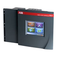
Front View and Rear View15
-
Colorful Touch Screen Interface17
-
Installation17
-
What this Chapter Contains17
-
Mounting17
-
Lead Connections18
-
Wiring Diagram19
-
Easy Start21
-
What this Chapter Contains21
-
Menu Navigation21
-
Legends for the Touch Screen Icons22
-
Title Bar23
-
Setting Area24
-
Status Bar24
-
Keyboard Entry Screen24
-
Starting the RVT25
-
Automatic Commissioning25
-
Description25
-
Preparation for Automatic Commissioning26
-
Automatic Commissioning26
-
Measurements and Settings30
-
What this Chapter Contains30
-
Measurements30
-
Overview31
-
System Values34
-
Zoom in / out the Chart36
-
Waveform37
-
Meter38
-
Event Logging39
-
Settings40
-
Manual Settings (Set Mode)41
-
Installation Settings50
-
User Settings52
-
Restore Default Settings56
-
Commissioning (SET Mode)57
-
Bank Monitoring60
-
Diagnosis60
-
Test Function61
-
Alarm Logging62
-
Real Time Clock63
-
Communications63
-
I/O Configuration66
-
Ethernet Configurations69
-
Screen Configuration70
-
About71
-
Mac Address72
-
Appendices73
-
A1. Dimensions73
-
A2. Technical Specifications73
-
A3. Testing and Troubleshooting77
-
A4. Post Alarm Restarting Procedure78
-
A5. Voltage Measurement and Power Supply Connection79
-
A6. Phase Shift Table (Applicable to Base Model)80
-
A7. CT Connection Type Illustration and CT Wiring on the Controller Terminals81
-
A8. Individual Phase Power Factor Control (Applicable for Three Phase Model RVT12-3P)82
-
A9. Recycling83
-
A10. Additional Provision on Open Source Software84
-
Instructions D'installation, D'utilisation et D'entretien85
-
A Lire en Premier86
-
A Propos de Ce Manuel D'instructions86
-
Avertissement86
-
Sécurité86
-
Compatibilité Électromagnétique86
-
Introduction au Régulateur87
-
Que Contient Ce Chapitre87
-
Un Régulateur de Facteur de Puissance Triphasé Qui Contrôle Efficacement Chaque Phase Individuellement87
-
Caractéristiques Principales du RVT87
-
Contrôle de la Compensation du Facteur de Puissance87
-
Mesures et Enregistrement87
-
Communications88
-
Vues des Faces Avant et Arrière88
-
Un Écran Tactile Multicolore90
-
Installation90
-
Que Contient Ce Chapitre90
-
Fixation90
-
Connexion des Câbles91
-
Schéma Électrique92
-
Démarrage Facile94
-
Que Contient Ce Chapitre94
-
Navigation Dans les Menus94
-
Légendes des Boutons Tactiles95
-
Barre de Titre96
-
Zone de Programmation97
-
Barre de Statut97
-
L'écran Clavier97
-
Mise en Route du RVT98
-
Mise en Service Automatique98
-
Préparation de la Mise en Service Automatique99
-
Mise en Service Automatique99
-
Mesures et Programmation103
-
Que Contient Ce Chapitre103
-
Mesures103
-
Vue D'ensemble104
-
Détail des Valeurs108
-
Formes D'ondes110
-
Grand Écran111
-
Enregistrements111
-
Paramètres113
-
Programmation Manuelle (Set Mode)114
-
Paramètres D'installation123
-
Paramètres de L'utilisateur125
-
Mise en Service (Mode SET)130
-
Surveillance Batterie133
-
Diagnostic134
-
Fonction Test134
-
Alarmes Enregistrées135
-
Horloge136
-
Communication136
-
Configuration Entrée/Sortie140
-
Unité de Température141
-
Paramètres de Communication141
-
Configurations Ethernet143
-
Configuration D'écran145
-
A Propos146
-
Adresse Mac146
-
Annexes147
-
A1. Dimensions147
-
A2. Spécifications Techniques147
-
A3. Test et Détection de Pannes151
-
A4. Procédure de Redémarrage après Disparition D'une Alarme153
-
A5. Connexions de L'alimentation et de la Mesure en Tension154
-
A6. Tableau des Connexions et Déphasages Associés (Applicable au Modèle de Base)154
-
A7. Type de Connexion TI et Câblage des TI Sur les Terminaux du Régulateur156
-
A8. Contrôle du Facteur de Puissance Phase Par Phase Individuellement (Valable pour le Modèle Triphasé RVT12-3P)157
-
A9. Recyclage158
-
A10. Additional Provision on Open Source Software159
-
Warnung161
-
Sicherheit161
-
Kommunikation163
-
Installation165
-
Montage165
-
Verdrahtungsplan167
-
Einfacher Start169
-
Titelleiste171
-
Einstellbereich171
-
Einstellungen172
-
Statusleiste172
-
Den RVT Starten173
-
Beschreibung174
-
Messungen178
-
Übersicht179
-
Detaildaten183
-
Wellenform186
-
Messgerät187
-
Ereignisspeicher187
-
Einstellungen189
-
Überwachung209
-
Schaltspiele209
-
Testfunktionen210
-
Alarmspeicher211
-
Echtzeituhr211
-
Kommunikation212
-
Über221
-
Mac Adresse221
-
Anhang222
-
A1. Abmessungen222
-
A9. Recycling235
-
Instrucciones de Instalación y de Funcionamiento237
-
Leer Esto Primero238
-
Sobre Este Manual de Instrucciones238
-
Advertencia238
-
Seguridad238
-
Introducción al Regulador239
-
Contenido del Capítulo239
-
Un Potente Regulador de Factor de Potencia con Control en las Tres Fases Individualmente239
-
Funciones Principales del RVT239
-
Control de Corrección del Factor de Potencia239
-
Mediciones y Supervisión240
-
Comunicaciones240
-
Vista Frontal y Vista Posterior240
-
Interfaz de Pantalla Táctil en Color242
-
Instalación242
-
Contenido del Capítulo242
-
Montaje242
-
Conexionado de Cables243
-
Esquema de Cableado244
-
Fácil Comienzo246
-
Contenido del Capítulo246
-
Navegación por Los Menús246
-
Simbología de Los Iconos de la Pantalla Táctil247
-
Barra de Título248
-
Área de Ajuste248
-
Barra de Estado248
-
Pantalla de Introducción Mediante Teclado250
-
Puesta en Marcha del RVT250
-
Puesta en Marcha Automática250
-
Descripción251
-
Preparación para la Puesta en Marcha Automática251
-
Puesta en Marcha Automática251
-
Mediciones y Parámetros255
-
Contenido del Capítulo255
-
Mediciones255
-
Vista General256
-
Valores del Sistema260
-
Forma de Onda263
-
Meter263
-
Registros264
-
Parámetros266
-
Ajuste Manual (Modo Modificar)266
-
Puesta en Servicio (Modo Modificar)283
-
Control de la Batería285
-
Diagnóstico285
-
Comprobar Función286
-
Histórico Alarma287
-
Reloj de Tiempo Real288
-
Comunicación288
-
Configuración E/S292
-
Configuraciones de Ethernet295
-
Configuración de la Pantalla296
-
A Cerca de297
-
Dirección Mac298
-
Anexos299
-
A1. Dimensiones299
-
A2. Especificaciones Técnicas299
-
A3. Prueba y Localización de Averías302
-
A4. Procedimiento de Reinicio Después de la Alarma305
-
A5. Conexión de la Medida de Tensión y de la Alimentación306
-
A6. Tabla de Desfase (Aplicable al Modelo Básico)307
-
A7. Ilustración del Tipo de Conexión de CT y Cableado de CT en Los Terminales del Regulador308
-
A8. Control del Factor de Potencia de Fase Individual (Aplicable al Modelo Trifásico RVT12-3P)309
-
A9. Reciclaje310
-
A10. Additional Provision on Open Source Software311
-
Rvt 安装和操作说明312
-
关于本使用手册的简介313
-
安全性313
-
电磁兼容性313
-
控制器入⻔介绍314
-
本章内容概述314
-
一款功能强大的可共补/分补的功率因数控制器314
-
Rvt 主要特点314
-
功率因数控制314
-
测量和监测314
-
通信设置314
-
前视图与后视图315
-
彩色触摸屏界面316
-
本章内容概述317
-
导线连接318
-
接线图319
-
轻松启动321
-
本章内容概述321
-
导航菜单321
-
触摸屏图标的注释322
-
标题栏323
-
设定区323
-
状态栏323
-
键盘输入界325
-
启动 Rvt326
-
自动调试326
-
自动调试的准备⼯作326
-
自动调试327
-
数据测量和参数设置331
-
本章内容概述331
-
数据测量331
-
系统数值332
-
参数设置341
-
手动设定值(设定模式342
-
调试(设定模式359
-
电容监测361
-
测试功能362
-
报警记录364
-
实时时钟364
-
通信设置365
-
I/O 配置369
-
以太网设置372
-
屏幕设置373
-
显⽰ Mac 地址375
-
A1. 外形尺寸376
-
A2. 技术规格376
-
A3. 测试和故障排除380
-
A4. 保护动作后重新启动程序382
-
A5. 电压测量和电源连接383
-
A6. 相位移表(适用于基本型号384
-
A7. 共补/分补 Ct 连接类型说明和控制器端⼦上的 Ct 接线385
-
A8. 分补或混补控制(适⽤于 Rvt12-3P 型号386
-
A9. 回收处理387
-
A10. Additional Provision on Open Source Software388
-
Instruções de Instalação E Operação389
-
Leia-Me390
-
Sobre Este Manual de Instruções390
-
Atenção390
-
Segurança390
-
Compatibilidade Eletromagnética390
-
Introdução Ao Controlador391
-
O que Este Capítulo ContéM391
-
Um Poderoso Controlador de Fator de Potência Trifásico Com Análise Individual de cada Fase391
-
Principais Caractrísticas Do RVT391
-
Controle da Correção Do Fator de Potência391
-
Medições E Monitoramento391
-
Comunicações392
-
Visões Frontal E Traseira392
-
Interface Touch Screen Colorida393
-
Instalação394
-
O que Este Capítulo ContéM394
-
Montagem394
-
Conexão de Cabos395
-
Diagrama de Ligação396
-
Início Simples398
-
O que Este Capítulo ContéM398
-
Menu de Navegação398
-
Legendas para os Ícones da Tela Touch Screen399
-
Barra de Títulos400
-
Área de Configurações400
-
Barra de Status400
-
Interface de Teclado401
-
Iniciando O RVT402
-
Comissionamento Automático402
-
Descrição402
-
Preparação para O Comissionamento Automático403
-
Comissionamento Automático403
-
Medições E Configurações407
-
O que Este Capítulo ContéM407
-
Visão Geral408
-
Medições da Rede408
-
Forma de Onda408
-
Banco de Medições408
-
Registro de Eventos416
-
Configurações417
-
Configurações Manuais (Modo "Set")418
-
Comissionamento (Modo Configuração)434
-
Comissionamento das Sondas436
-
Monitoramento Do Banco437
-
Diagnóstico438
-
Função Teste438
-
Registro de Alarme439
-
Relógio Com Horário Real440
-
Comunicações440
-
Configurações I/O444
-
Configurações Ethernet447
-
Configuração da Tela448
-
Sobre449
-
Endereço MAC450
-
Apêndices450
-
A1. Dimensões450
-
A2. Especificações Técnicas451
-
A3. Testes E Solução de Problemas454
-
A4. Procedimento para Reinício Pós Alarme456
-
A5. Medição de Tensão E Conexão de Fonte de Alimentação457
-
A6. Tabela de Mudança de Fase (Aplicável Ao Modelo Base)458
-
A7. Ilutração Dos Tipos de Conexão Dos Tcs E Dos Cabos Do TC Nos Terminais Do Controlador459
-
A8. Controle de Fator de Potência Monofásico (Aplicável para O Modelo Trifásico RVT12-3P)460
-
A9. Reciclagem461
-
A10. Additional Provision on Open Source Software461
-
Инструкция По Монтажу И Эксплуатации463
-
Прочитать В Первую Очередь464
-
Об Этой Инструкции По Эксплуатации464
-
Предупреждение464
-
Техника Безопасности464
-
Электромагнитная Совместимость (ЭМС)465
-
Вводная Информация По Контроллеру RVT465
-
Содержание Главы465
-
Мощный Трехфазный Контроллер Для Независимого Регулирования Коэффициента465
-
Основные Функциональные Возможности Контроллера RVT465
-
Управление Коррекцией Коэффициента Мощности465
-
Измерения И Мониторинг466
-
Средства Связи466
-
Вид Спереди И Вид Сзади467
-
Интерфейс На Основе Цветного Сенсорного Дисплея468
-
Монтаж469
-
Содержание Главы469
-
Порядок Установки469
-
Подключение Выводов470
-
Схема Электрических Соединений471
-
Простой Запуск472
-
Содержание Главы472
-
Система Меню473
-
Условные Графические Обозначения На Сенсорном Экране473
-
Строка Заголовка475
-
Область Ввода Настроек475
-
Строка Состояния476
-
Окно Ввода С Клавиатуры477
-
Запуск Контроллера RVT477
-
Автоматический Ввод В Эксплуатацию478
-
Описание478
-
Подготовка К Автоматическому Вводу В Эксплуатацию478
-
Автоматический Ввод В Эксплуатацию482
-
Измерения И Настройки482
-
Содержание Главы482
-
Измерения483
-
Обзор484
-
Системные Параметры488
-
Временные Диаграммы Сигналов490
-
Измерительный Прибор491
-
Журнал Событий492
-
Настройки493
-
Ручной Ввод Настроек (Режим Set)494
-
Предупреждения509
-
Тепловая Защита509
-
Ввод В Эксплуатацию (Режим Set)511
-
Мониторинг Батареи Конденсаторов514
-
Диагностика515
-
Функция Тестирования515
-
Регистрация Аварийных Сигналов517
-
Часы Реального Времени517
-
Связь518
-
Конфигурация Средств Ввода-Вывода521
-
Выбор Языка522
-
Настройки Конфигурации Сети Ethernet525
-
Конфигурация Экрана526
-
Информация О Контроллере527
-
MAC-Адрес Контроллера528
-
Приложения528
-
A1. Габаритные Размеры528
-
A2. Технические Характеристики529
-
A3. Проверка Работоспособности И Поиск Неисправностей532
-
A4. Процедура Перезапуска После Возникновения Аварийного Сигнала534
-
A5. Измерение Напряжения И Подключение К Источнику Питания535
-
A6. Таблица Сдвига Фаз (Применяется В Базовой Модели)537
-
A7. Иллюстрация Типа Подключения ТТ И Схема Подключения ТТ К Клеммам Контроллера538
-
A8. Регулирование Коэффициента Мощности В Отдельных Фазах539
-
Модели RVT12-3P)539
-
A9. Вторичная Переработка540
-
A10. Дополнительные Положения, Действующие В Отношении ПО С Открытым Исходным Кодом541
-
Introduction to the Controller546
-
Intended Audience546
-
Before You Start546
-
How to Use this Manual546
-
Software Protocols and Physical Interface546
-
Modbus Protocol Overview547
-
Overview547
-
RS485 Modbus Adapter547
-
Transactions on Modbus Networks548
-
Serial Transmission Mode549
-
Modbus Message Framing550
-
Modbus Function Codes553
-
Data Addresses in Modbus Messages553
-
Supported Function Codes553
-
Master's Queries and Slave's Responses554
-
Reads and Writes to Modbus Addresses (Functions 1, 2, 3, 4, 5, 6, 15, 16, 22, 23)554
-
Fetch Comm Event Counter (Function 11)555
-
Fetch Comm Event Log (Function 12)555
-
Diagnostics Function and Subfunctions (Function 8)557
-
Exception Responses558
-
CRC Generation559
-
Input Parameters559
-
Ethernet / RJ45 and USB Connections for PQ-Link Protocol561
-
General Overview561
-
Physical Layer561
-
Tcp/Ip561
-
Usb562
-
Framing Layer & Command Layer563
-
Data Table564
-
Overview564
-
Parameter Types564
-
Parameter Changes and Access565
-
Parameter Groups566
-
Configuration566
-
Parameter List567
-
Configuration (Universal)568
-
Configuration (Access Protected)570
-
Configuration (RVT Specific)582
-
Source Ids598
-
Windows Communication DLL for PQ-Link Protocol599
-
Introduction599
-
Interface599
-
Opening and Closing600
-
Authentication601
-
Parameter Access602
-
Curve Access604
-
Miscellaneous606
-
Important Considerations606
-
Visual Basic 6.0 Support606
-
Multi-Threading606
-
Sequence of Actions606
-
Error Codes607
-
Example Codes608
-
Visual Basic 6.0 Project608
-
Appendices608
-
A1 List of Abbreviations608
-
A2 References612
-
A3 Description of Open Ports612
-
A4 Cyber Security Disclaimer Note612
-
Introduction617
-
Intended Audience617
-
Before You Start617
-
How to Use this Manual617
-
Overview617
-
Introduction to Modbus617
-
The Modbus Adapter617
-
Compatibility618
-
Serial Interface Considerations618
-
Communication Mode618
-
SINGLE ENDED Versus DIFFERENTIAL Data Transmission619
-
RS-232 Interface619
-
RS-422 Interface619
-
RS-485 Interface619
-
Bias Resistors620
-
Termination Resistors620
-
Shielding and Grounding Considerations620
-
Cable Requirements620
-
Network Topology621
-
RS485 Modbus Adapter621
-
Main Features621
-
Physical Dimensions622
-
Mounting622
-
Technical Data623
-
Commissioning Process623
-
To Set the COMMUNICATION LOCK Parameter624
-
To Test the Communication625
-
Modbus Protocol Overview625
-
Overview625
-
Transactions on Modbus Networks625
-
Serial Transmission Mode625
-
Data Addresses in Modbus Messages625
-
Supported Function Codes626
-
Data Access626
-
Access Levels626
-
Minimum and Maximum Values627
-
Modbus Data Table627
-
Troubleshooting627
-
Preferred Method of Testing627
-
Check of Identical Slave - Master Configuration628
-
Check the Cabling of the RS485628
-
Check the Transmit - Receive Indicators628
-
Check the Function Called and the Register Addresses628
-
Check the Data Access Level and the Limited Range of Data629
-
Counters and Loopback Diagnostics629
-
Debugging Tool and Documents629
-
Appendices629
-
A1 List of Abbreviations629
-
A3 Adequate Choice of an RS232-RS485 Converter at the Computer Side632
-
Temperature Probe634
-
Technical Specifications635
-
Mechanical Dimensions635
-
Installation and Commissioning636
-
Steps for Installation639