Inhaltsverzeichnis
Werbung
Verfügbare Sprachen
Verfügbare Sprachen
Quicklinks
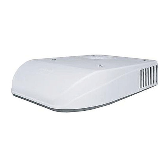
RV ROOF TOP AIR CONDITIONER/HEAT PUMP
INSTRUCTIONS D'INSTALLATION
CLIMATISEUR / THERMOPOMPE DE TOIT POUR VR
RV DACHKLIMAANLAGE/WÄRMEPUMPE
INSTRUCCIONES DE INSTALACIÓN
AIR ACONDICIONADO/BOMBA DE CALOR PARA TECHO RV
Coleman is a registered trademark of The Coleman Company, Inc. used under license. Mach is a registered trademark.
RV Products Division
INSTALLATION INSTRUCTIONS
230/240 VAC, 1ø, 50Hz
47000 SERIES
POUR LE
SÉRIE 47000
de 230/240 V CA, 1 ø, 50 Hz
INSTALLATIONSANLEITUNG
230/240 VAC, 1ø, 50 Hz
47000 SERIE
PARA LA
230/240 VAC, 1ø, 50Hz
SERIE 47000
FOR
FÜR
Werbung
Inhaltsverzeichnis

Verwandte Anleitungen für Airxcel Coleman Mach 47000-Serie


Inhaltszusammenfassung für Airxcel Coleman Mach 47000-Serie
- Seite 1 RV Products Division INSTALLATION INSTRUCTIONS 230/240 VAC, 1ø, 50Hz 47000 SERIES RV ROOF TOP AIR CONDITIONER/HEAT PUMP INSTRUCTIONS D’INSTALLATION POUR LE CLIMATISEUR / THERMOPOMPE DE TOIT POUR VR SÉRIE 47000 de 230/240 V CA, 1 ø, 50 Hz INSTALLATIONSANLEITUNG FÜR 230/240 VAC, 1ø, 50 Hz 47000 SERIE RV DACHKLIMAANLAGE/WÄRMEPUMPE...
-
Seite 2: Inhaltsverzeichnis
INQUIRIES ABOUT THE A/C UNIT – Inquiries to your and Model Number may be viewed from the rear at the center Airxcel, Inc. representative or to Airxcel, Inc. pertaining to of the basepan under the plastic shroud. product installation should contain both the model and serial... -
Seite 3: Heat Pump Sizing
II. HEAT PUMP SIZING The ability of a heat pump in the cooling mode to cool a As long as this temperature difference (15 to 20 degrees F, 8 vehicle or maintain a consumer desired temperature is to 12 degrees C) is being maintained, the unit is operating dependent on the heat gain of the vehicle. - Seite 4 IMPORTANT – Allow 600mm of supply wiring collapsing occurs. through the support frame (working length). Airxcel, Inc. recommends that the spacing from the After the support frame is installed, seal all gaps vehicle roof top to the interior ceiling top be no less between the frame and both the roof exterior and the than 25mm.
-
Seite 5: Securing The Heat Pump To The Roof
If the roof of the vehicle is sloped such that the heat Once the heat pump has been leveled, some pump cannot be mounted within the maximum additional shimming may be required above the allowable degree deviations, an exterior leveling interior ceiling assembly. - Seite 6 FIGURE 4...
-
Seite 7: Electrical Wiring
VI. ELECTRICAL WIRING ROUTING 230/240 VAC WIRING DANGER See Figure 4 WITH NON-METALLIC SHEATH Following high voltage wiring specifications and all local and CABLES (ROMEX, ETC.), STRIP national electrical codes, route the 230/240 VAC supply SHEATH BACK TO EXPOSE wiring from its power source through the strain relief and 100-150mm OF SUPPLY LEADS. - Seite 8 VII.
-
Seite 9: Installing The 9430-451 Ceiling Assembly
VIII. INSTALLING THE 9430-451 CEILING ASSEMBLY Refer to Figures 5 and 6 NOTE Align the shroud with the air chute insuring that no wires are trapped between plastic parts. Attach the The following step by step instructions must be performed in shroud to the steel frame with 4 short screws sequence to insure a quick and easy installation. - Seite 10 FIGURE 6...
-
Seite 11: Avertissement De Sécurité
Airxcel, Inc. ou de Airxcel, Inc. en ce qui concerne l’installation du produit devraient contenir plastique. -
Seite 12: Évaluation De La Taille De La Thermopompe
II. ÉVALUATION DE LA TAILLE DE LA THERMOPOMPE La capacité de refroidissement d’un véhicule ou de maintien Encore une fois, accordez une attention particulière aux de la température souhaitée par le consommateur d’une variables de gain de chaleur du véhicule. Lors des thermopompe dépend du gain de chaleur du véhicule. - Seite 13 L’extrémité pointue (nez) du carénage doit être orientée vers l’avant du véhicule. Tirez tous les Airxcel, Inc. recommande un écart minimum connecteurs électriques lâches de la thermopompe à travers l’ouverture de montage et laissez-les pendre. de 25 mm (1 po) entre le toit du véhicule et le...
-
Seite 14: Fixation De La Thermopompe Au Toit
V. FIXATION DE LA THERMOPOMPE AU TOIT Voir Figure 4 Un cadre de montage est fourni avec l’assemblage de plafond. figure 4). La partie supérieure a maintenant été Suivez les étapes ci-dessous pour fixer la thermopompe au correctement installée avec une compression de joint toit. -
Seite 15: Installation De L'assemblage De Plafond 9430-451
VIII. INSTALLATION DE L’ASSEMBLAGE DE PLAFOND 9430-451 Reportez-vous aux figures 5 et 6 Alignez le carénage avec la goulotte d’air en vous REMARQUE assurant de ne coincer aucun fil entre les composants Les instructions étape par étape suivantes doivent être suivies en plastique. -
Seite 16: Warnung - Stromschlaggefahr
Wenn die Wärmepumpe installiert ist, sind Hersteller und FRAGEN ZUR KLIMAANLAGE – Bitte geben Sie bei Modellnummer auch von der Rückseite in der Mitte der Anfragen bei Ihrem Airxcel, Inc.-Vertreter oder Airxcel, Inc. Bodenwanne unter der Kunststoffblende zu sehen. bezüglich der Produktinstallation sowohl die Modell- als auch die Seriennummer der dachseitigen Einheit an. -
Seite 17: Dimensionierung Der Wärmepumpe
II. DIMENSIONIERUNG DER WÄRMEPUMPE Die Fähigkeit einer Wärmepumpe im Kühlmodus, ein Temperaturunterschied (15 bis 20 °C, bzw. 8 bis 12 °C) Fahrzeug zu kühlen oder die vom Verbraucher gewünschte aufrechterhalten wird, funktioniert das Gerät ordnungsgemäß. Temperatur aufrechtzuerhalten, hängt von der Wärmeaufnahme des Fahrzeugs ab. -
Seite 18: Befestigung Der Wärmepumpe Auf Dem Dach
Kunststoffverkleidung an. Stellen Sie die zusammenklappen. Wärmepumpe auf die vorbereitete Montageöffnung. Das spitze Ende (Nase) der Verkleidung Airxcel, Inc. empfiehlt einen Abstand von der muss zur Vorderseite des Fahrzeugs weisen. Ziehen Oberseite des Fahrzeugdachs zur Oberseite der Sie alle losen elektrischen Anschlüsse von der Innendecke von mindestens 25 mm. -
Seite 19: Elektrische Verkabelung
Siehe Abb. 4 ISOLIEREN SIE BEI VERWENDUNG VON Verlegen Sie unter Befolgung der Spezifikationen für NICHTMETALLISCHEN MANTELKABELN Hochspannungsverkabelung von Airxcel, Inc. und aller (ROMEX USW.) lokalen und nationalen Stromvorschriften das 230/240-VAC- DEN MANTEL AB, SODASS 100–150 mm DES Stromkabel von der Stromquelle über die Zugentlastung und VERSORGUNGSKABELS FREI LIEGT. -
Seite 20: Installieren Der Deckeneinheit (9430-451)
VIII. INSTALLIEREN DER DECKENEINHEIT (9430-451) Siehe Abb. 5 und 6 HINWEIS Richten Sie die Blende mit dem Luftkanal aus und achten Sie dabei darauf, dass keine Die folgende schrittweise Anleitung muss in der angegebenen Drähte zwischen den Kunststoffteilen eingeklemmt Reihenfolge durchgeführt werden, um eine schnelle und werden. -
Seite 21: Información General
Airxcel, Inc. o para número de modelo se pueden ver desde la parte posterior hacia Airxcel, Inc. con respecto a la instalación del producto deben el centro de la bandeja base debajo de la cubierta de plástico. - Seite 22 II. MEDIDAS DE LA BOMBA DE CALOR La capacidad de la bomba de calor para enfriar un vehículo o (15 a 20 grados °F; 8 a 12 grados °C) se mantenga, la unidad mantener una temperatura deseada, depende de la ganancia de funcionará...
- Seite 23 (nariz) de la cubierta debe apuntar hacia el frente del vehículo. Haga pasar todas las Airxcel, Inc. recomienda que el espacio entre la parte conexiones eléctricas sueltas de la bomba de calor superior del techo exterior y la parte superior del por la abertura de instalación y déjelas colgando.
-
Seite 24: Cableado Eléctrico
VI. CABLEADO ELÉCTRICO CABLEADO DE 230/240 VCA PELIGRO Ver Figura 4 CON CABLES DE FUNDA NO METÁLICA Conforme a las especificaciones de cableado de alto voltaje y (ROMEX, ETC.), PELE LA FUNDA PARA de todos los códigos eléctricos nacionales y locales, coloque el EXPONER LAS PUNTAS DE 100 mm a 150 mm. - Seite 25 sensor cuelgue a un lado del conducto. Conecte el aire de salida no le pegue al control remoto y dentro de “línea de visión” para el sensor del ensamble del cable de conexión de la unidad superior al receptáculo en la cubierta del techo, como se muestra techo.
- Seite 26 Airxcel, Inc. RV Products Division P.O. Box 4020 Wichita, KS 67204 1976-686 (11-15) PP...