
Verwandte Anleitungen für FS S5850-24S2Q-DC


Inhaltszusammenfassung für FS S5850-24S2Q-DC
- Seite 1 S5850-24S2Q-DC MANAGED L2/L3 ROUTING SWITCH MANAGED L2/L3 ROUTING SWITCH COMMUTATEURS DE ROUTAGE L2/L3 GÉR Quick Start Guide V1.0 Quick-Start Anleitung Guide de Démarrage Rapide...
-
Seite 2: Accessories
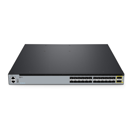
Introduction Thank you for choosing S5850-24S2Q-DC switch. This guide is designed to familiarize you with the layout of the switch and describe how to deploy the switch in your network. ID SYS 10 11 14 15 16 17 18 19... -
Seite 3: Hardware Overview
QSFP+ ID SYS 10 11 14 15 16 17 18 19 20 21 22 23 S5850-24S2Q-DC 40GE Breakout Ports Description SFP+ SFP+ ports for 1/10G transceivers QSFP+ QSFP+ ports for 40G or 4x 10G connection An RJ45 console port for serial management... -
Seite 4: Back Panel
LEDs Status Description Green 10G port is linked. Blinking Green The SFP+ port is transmitting or receiving packets at 10G. SFP+ Amber 1G port is linked. Blinking Amber The SFP+ port is transmitting or receiving packets at 1G. Port is not linked. Green 40G port is linked. -
Seite 5: Installation Requirements
Installation Requirements Before you begin the installation, make sure that you have the following: Phillips screwdriver. M6 Screws. Standard-sized, 19" wide rack with a minimum of 1U height available. Category 5e or higher RJ-45 Ethernet cables for connecting the network devices. ID SY S CO N ET H... -
Seite 6: Rack Mounting
Rack Mounting 14 15 16 17 18 19 20 21 22 23 40 G 40 GE Br ea ko ut 1. Secure the mounting brackets to the two sides of the switch with eight M4 screws. 1 4 1 5 1 6 1 7 1 8 1 9 2 0 2 1... -
Seite 7: Connecting The Power
Grounding the Switch ID SY S CO N ET H S 5 8 5 0 -2 4 S 2 Q NU LL -4 8V - -6 0V ,6 A 1. Connect one end of the grounding cable to a proper earth ground, such as the rack in which the switch is mounted. - Seite 8 Connecting the SFP+ Ports 14 15 16 17 18 19 20 21 22 23 40 G 40 G E Br ea ko ut First install SFP+ transceivers and then connect ber optic cabling to the transceiver ports, or directly connect DAC cables to the SFP+ slots. CAUTION: Laser beams will cause eye damage.
- Seite 9 Connecting the Management Ports Connecting the Console Port ID SY S CO N ET H 1. Insert the RJ45 connector of the console cable into the RJ45 console port on the front of the switch. 2. Connect the other end of the console cable to the RS-232 serial port on the computer. Connecting the ETH Port ID SY S CO N...
- Seite 10 Connecting the USB Port ID SY S CO N ET H 14 15 16 17 18 19 20 21 22 23 40 G 40 GE Br ea ko ut Insert the Universal Serial Bus (USB) ash disk to the USB port for software and con guration backup and o ine software upgrade.
- Seite 11 Step 3: Open a browser, type http://192.168.1.1, and enter the default username and password, admin/admin. Step 4: Click sign in to display the web-based con guration page. Con guring the Switch Using the Console Port Step 1: Connect a computer to the switch's console port using the supplied console cable. Step 2: Start the terminal simulation software such as HyperTerminal on the computer.
- Seite 12 Troubleshooting Loading Failure Troubleshooting After loading fails, the system will keep running in the original version. At this time, users should re-check if physical port connections are good rstly. If some ports are not connected, then re-connect them to ensure that physical connections are correct, and begin re-loading. If physical connections are correct, then check the loading process information displayed on the super terminal to verify if there are input errors.
-
Seite 13: Support And Other Resources
Product Warranty FS ensures our customers that any damage or faulty items due to our workmanship, we will o er a free return within 30 Days from the day you receive your goods. This excludes any custom made items or tailored solutions. - Seite 14 Introduction Merci d'avoir choisi le switch S5850-24S2Q-DC. Ce guide est conçu pour que vous puissiez vous familiariser avec la con guration du switch et vous indiquer comment procéder à son déploiement. ID SYS 10 11 14 15 16 17 18 19...
-
Seite 15: Aperçu Du Matériel
QSFP+ ID SYS 10 11 14 15 16 17 18 19 20 21 22 23 S5850-24S2Q-DC 40GE Breakout Ports Description SFP+ Ports SFP+ pour modules 1/10G QSFP+ Ports QSFP+ pour connexion 40G ou 4x 10G Port console RJ45 pour la gestion série... -
Seite 16: Panneau Arrière
Indicateur Statut Description Éteint Le port n'est pas relié Vert Le port 10G est relié Vert Clignotant Le port SFP+ transmet ou reçoit des paquets à 10G SFP+ Jaune Le port 1G est relié Jaune Clignotant Le port SFP+ transmet ou reçoit des paquets à 1G Éteint Le port n'est pas relié... -
Seite 17: Exigences D'installation
Exigences d'Installation Avant de commencer l'installation, assurez-vous que vous disposez des éléments suivants : Tournevis phillips. Vis M6 Rack de taille standard, 19" de large, avec une hauteur minimum de 1U. ID SY S Câbles Ethernet RJ-45 de catégorie 5e ou supérieure pour la connexion des périphériques réseau. CO N ET H S 5 8 5 0 -2... -
Seite 18: Montage Sur Rack
Montage sur Rack 14 15 16 17 18 19 20 21 22 23 40 GE Br ea 40 G ko ut 1. Fixez les supports de montage aux deux côtés du switch à l'aide de huit vis M4. 1 4 1 5 1 6 1 7 1 8 1 9 2 0 2 1... -
Seite 19: Connexion De L'alimentation
Mise à la Terre du Switch ID SY S CO N ET H S 5 8 5 0 -2 4 S 2 Q NU LL -4 8V - -6 0V ,6 A 1. Connectez une extrémité du câble de mise à la terre à une mise à la terre appropriée, telle que le rack dans lequel le switch est monté. - Seite 20 Connexion des Ports SFP+ 14 15 16 17 18 19 20 21 22 23 40 G 40 GE Br ea ko ut Installez d'abord les modules SFP+, puis connectez les câbles en bre optique aux ports des modules, ou connectez directement les câbles DAC aux emplacements SFP+. ATTENTION : Les faisceaux laser peuvent causer des lésions oculaires.
- Seite 21 Connexion des Ports de Gestion Connexion du Port Console ID SY S CO N ET H 1. Insérez le connecteur RJ45 du câble de la console dans le port de console RJ45 situé sur la face frontale du switch. 2. Connectez l'autre extrémité du câble de la console au port série RS-232 de l'ordinateur. Connexion au Port ETH ID SY S CO N...
- Seite 22 Connexion au Port USB ID SY S CO N ET H 14 15 16 17 18 19 20 21 22 23 40 G 40 GE Br ea ko ut Insérez le dispositif USB dans le port USB pour la sauvegarde du logiciel, et de la con guration et la mise à...
- Seite 23 Étape 3 : Ouvrez un navigateur, tapez http://192.168.1.1, et entrez le nom d'utilisateur et le mot de passe par défaut : admin/admin. Étape 4 : Cliquez sur Connexion pour a cher la page de con guration basée sur le Web. Con guration du Switch à...
- Seite 24 Dépannage du Système Dépannage en Cas d'Échec du Chargement Après l'échec du chargement, le système fonctionnera dans sa version originale. À ce moment-là, il est conseillé de revéri er d'abord si les connexions des ports physiques sont bien établies. Si certains ports ne sont pas connectés correctement, reconnectez-les pour vous assurer que les connexions physiques sont bien établies, puis commencez à...
-
Seite 25: Garantie Du Produit
Garantie du Produit FS garantit à ses clients que tout article endommagé ou défectueux dû à sa fabrication pourra être retourné gratuitement dans un délai de 30 Jours à compter de la date de réception de la marchan- dise, à l'exception des articles fabriqués sur mesure ou des solutions personnalisées. -
Seite 26: Einführung
Einführung Vielen Dank, dass Sie sich für den S5850-24S2Q-DC Switch entschieden haben. Diese Anleitung soll Sie mit dem Layout des Switches vertraut machen und beschreibt, wie Sie den Switch in Ihrem Netzwerk einsetzen. ID SYS 10 11 14 15 16 17... -
Seite 27: Hardware-Übersicht
SFP+ QSFP+ ID SYS 10 11 14 15 16 17 18 19 20 21 22 23 S5850-24S2Q-DC 40GE Breakout Ports Description SFP+ SFP+-Ports für 10G Transceiver QSFP+ QSFP+-Ports für 40G oder 4x 10G-Verbindungen Ein RJ45-Console-Port für die serielle Verwaltung Ein RJ45 Ethernet Management Port Ein USB-Management-Port für Software- und... -
Seite 28: Beschreibung Description
Ports Beschreibung Description Der Port ist nicht verbunden. Leuchtet Grün 10G-Port ist verbunden. Blinkt Grün Der SFP+-Port sendet oder empfängt Pakete mit 10G. SFP+ Leuchtet Gelb 1G-Port ist verbunden. Blinkt Gelb Der SFP+-Port sendet oder empfängt Pakete mit 1G. Der Port ist nicht verbunden. Leuchtet Grün 40G-Port ist verbunden. -
Seite 29: Installationsvoraussetzungen
Installationsvoraussetzungen Bevor Sie mit der Installation beginnen, vergewissern Sie sich, dass Sie folgende Materialien besitzen: Kreuzschlitzschraubendreher. M6 Schrauben. Ein 19"-Rack in Standardgröße mit einer Mindesthöhe von 1HE. ID SY S RJ-45-Ethernet-Kabel der Kategorie 5e oder höher für den Anschluss der Netzwerkgeräte. CO N ET H S 5 8 5 0 -2... -
Seite 30: Rackmontage
Rack-Montage 14 15 16 17 18 19 20 21 22 23 40 GE Br ea 40 G ko ut 1. Befestigen Sie die Montagehalterungen mit acht M4-Schrauben an den beiden Seiten des Switches. 1 4 1 5 1 6 1 7 1 8 1 9 2 0 2 1 2 2 2 3... -
Seite 31: Erdung Des Switches
Erdung des Switches ID SY S CO N ET H S 5 8 5 0 -2 4 S 2 Q NU LL -4 8V - -6 0V 1. Schließen Sie ein Ende des Erdungskabels an eine geeignete Erdung an, z. B. an das Rack, in dem der Switch montiert ist. -
Seite 32: Anschließen Der Sfp+-Ports
Anschließen der SFP+-Ports 14 15 16 17 18 19 20 21 22 23 40 G 40 G E Br ea ko ut IInstallieren Sie zuerst SFP+-Transceiver und verbinden Sie dann Glasfaserkabel mit den Transceiver-Ports oder schließen Sie DAC-Kabel an die SFP+-Schnittstelle an. WARNUNG: Laserstrahlen können zu Augenschäden führen. -
Seite 33: Anschließen Der Management-Ports
Anschließen der Management-Ports Anschließen des Console-Ports ID SY S CO N ET H 1. Stecken Sie den RJ45-Stecker in den RJ45 Console-Port an der Vorderseite des Switches. 2. Schließen Sie das andere Ende des Konsolenkabels an die serielle Schnittstelle RS-232 des Computers an. -
Seite 34: Anschließen Des Usb-Ports
Anschließen des USB-Ports ID SY S CO N ET H 14 15 16 17 18 19 20 21 22 23 40 G E Br ea 40 G ko ut Stecken Sie die Universal Serial Bus (USB) Ascheplatte in den USB-Port für Software- und Kon gurationssicherung und O ine-Software-Upgrade. -
Seite 35: Kon Gurieren Des Switches Über Den Console-Port
Schritt 3: Ö nen Sie einen Browser, geben Sie http://192.168.1.1 ein, und geben Sie den Standardbenutzernamen und das Standardkennwort admin/admin ein. Schritt 4: Klicken Sie auf Login, um die webbasierte Kon gurationsseite anzuzeigen. Kon gurieren des Switches über den Console-Port Schritt 1: Schließen Sie einen Computer über das mitgelieferte Konsolenkabel an den Konsolenanschluss des Switches an. -
Seite 36: Fehlerbehebung Bei Ladefehlern
Fehlerbehebung Fehlerbehebung bei Ladefehlern Wenn das Laden fehlschlägt, läuft das System in der ursprünglichen Version weiter. Zu diesem Zeitpunkt sollten die Benutzer zunächst überprüfen, ob die physischen Port-Verbindungen in Ordnung sind. Wenn einige Ports nicht angeschlossen sind, schließen Sie sie erneut an, um sicherzustellen, dass die physikalischen Verbindungen korrekt sind, und beginnen Sie mit dem erneuten Laden. -
Seite 37: Support Und Andere Ressourcen
Produktgarantie FS garantiert seinen Kunden, dass wir bei Schäden oder fehlerhaften Artikeln, die auf unsere Verarbeitung zurückzuführen sind, eine kostenlose Rückgabe innerhalb von 30 Tagen nach Erhalt der Ware anbieten. Dies gilt nicht für maßgefertigte Artikel oder maßgeschneiderte Lösungen. -
Seite 38: Compliance Information
Any changes or modi cations not expressly approved by the grantee of this device could void the user's authority to operate the equipment. Responsible party (only for FCC matter) FS.COM Inc. 380 Centerpoint Blvd, New Castle, DE 19720, United States https://www.fs.com... - Seite 39 Die FS.COM GmbH erklärt hiermit, dass dieses Gerät mit der Richtlinie 2014/30/EU und 2014/35/EU konform ist. Eine Kopie der EU-Konformitätserklärung nden Sie unter www.fs.com/de/company/quality_control.html. FS.COM GmbH déclare par la présente que cet appareil est conforme à la Directive 2014/30/UE et 2014/35/UE. Une copie de la Déclaration UE de Conformité est disponible sur https://www.fs.com/fr/company/quality_control.html FS.COM LIMITED...