
Verwandte Anleitungen für FS S5850-24XMG-U


Inhaltszusammenfassung für FS S5850-24XMG-U
- Seite 1 ID MGM T 100G Brea kout S5850-24XMG-U ETHERNET L3 SWITCHES Ethernet L3-Switches Switchs Ethernet L3 Quick Start Guide V1.0 Quick Start Anleitung Guide de Démarrage Rapide...
-
Seite 2: Accessories
Introduction Thank you for choosing S5850-24XMG-U Series Switches. This guide is designed to familiarize you with the layout of the S5850-24XMG-U Series Switches and describes how to deploy them in your network. 100G SYS ID MGMT POE Breakout S5850-24XMG-U Accessories... -
Seite 3: Hardware Overview
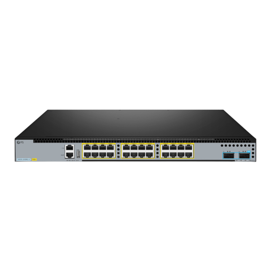
Hardware Overview Front Panel Ports S5850-24XMG-U 100G SYS ID MGMT POE Breakout MGMT RJ45 QSFP 28 Ports Description A RJ45 console port for serial management A USB management port for software configuration backup and offline software upgrade MGMT An out-of-band Ethernet management port... -
Seite 4: Back Panel
LEDs State Description The port is linked on 100M/1000M. Green MGMT Blinking The port is linked and there is data activity. The port is linked off. The remaining power of the PSE subsystem is less than Green (ON) the alarm threshold. The remaining power of the PSE subsystem is greater Yellow (ON) than the alarm threshold. -
Seite 5: Installation Requirements
Installation Requirements Before installation, make sure that you have the following conditions ready: Phillips screwdriver. Standard-sized, 19" wide rack with a minimum of 1U height available. Category 5e or higher RJ-45 Ethernet cables for connecting network devices. Site Environment: ID MG MT Make sure that the temperature of installation site is maintained at 0°~50°. -
Seite 6: Rack Mounting
Rack Mounting 100 G Brea kou t 1. Secure the mounting brackets to the two sides of the switch with eight M4 screws. 10 0G Bre ako ut ID MGM T 2. Attach the switch to the rack with four M6 screws and cage nuts. - Seite 7 Rack Mounting-Single Switch Deployment 1. Fix the mounting bracket to the one side of the switch. And fix the rear mounting bracket to the rack with two M4 screws. 2. Fix the sliding rail to the one side of switch with two M4 screws. And assemble the rear mounting brackets as the following picture.
- Seite 8 Installing the Power Supply Module P W R 1 P W R 1 1. Take a new power module out of the package and confirm the input mode and the input parameters of the power module match the requirements. 2. Remove the old power module and take the plane printed with power information as the top panel. Hold the handle of the power module with one hand, and hold the end with the other hand.
- Seite 9 Grounding the Switch 1. Connect one end of the grounding cable to a proper earth ground, such as the rack in which the switch is mounted. 2. Secure the grounding lug to the grounding point on the switch back panel with the washers and screws.
-
Seite 10: Connecting The Power
Connecting the Power CO N MG MT S5 85 0-2 4X ID MG MT 1. Plug the AC power cord into the power port on the back of the switch. 2. Connect the other end of the power cord to an AC power source. WARNING: Do not install power cords while the power is on. - Seite 11 Connecting the QSFP 28 Port 100 G Bre ako ut 1. Plug the compatible QSFP28 optical module into the QSFP28 port. 2. Connect one end of a fiber optic cable to the optical module. Then connect the other end of the cable to another fiber device.
- Seite 12 Connecting the Management Ports Connecting the CONSOLE Port ID MGM T 1. Insert the RJ45 connector of the console cable into the console port of the switch. 2. Connect the DB9 female connector of the console cable to the serial port of the computer. Connecting the MGMT Port CO N MG MT...
- Seite 13 Connecting the USB Port ID MG MT PO E 100G Brea kout Insert the Universal Serial Bus (USB) flash disk to the USB port for software and configuration backup and offline software upgrade. Bre ako ut...
- Seite 14 Configuring the Switch Configuring the Switch via the Web-based Interface Step 1: Connect your computer to the Management port of the Switch using the network cable. Step 2: Set the IP address of the computer to 192.168.1.x ("x" is any number from 2 to 254). I nter ne t Proto co l Ve rs i on 4 ( TC P / IP v4) Pro pe r t i es General Yo u c a n g e t I P s e t t i n g s a s s i g n e d a u t o m a t i c a l l y i f y o u r n e t w o r k...
- Seite 15 Configuring the Switch via the Console Port Step 1: Connect a computer to the switch's console port using the console cable. Step 2: Start the terminal simulation software such as HyperTerminal on the computer. Step 3: Set the parameters of the HyperTerminal: 9600 bits per second, 8 data bits, no parity, 1 stop bit and no flow control.
- Seite 16 Troubleshooting The Power Module Cannot Supply Power All LEDs on the front panel, the fan module and the panel of the power module are off. The fan does not work. First disconnect the power cord of the power module, then check the following: 1.
-
Seite 17: Online Resources
Product Warranty FS ensures our customers that any damage or faulty items due to our workmanship, we will offer a free return within 30 Days from the day you receive your goods. This excludes any custom-made items or tailored solutions. -
Seite 18: Einführung
Einführung Vielen Dank, dass Sie sich für Switches der Serie S5850-24XMG-U entschieden haben. Diese Anleitung soll Sie mit dem Layout der S5850-24XMG-U Serie Switches vertraut machen und beschreibt, wie Sie diese in Ihrem Netzwerk einsetzen können. 100G SYS ID MGMT POE... -
Seite 19: Hardware-Übersicht
Hardware-Übersicht Ports an der Vorderseite S5850-24XMG-U 100G SYS ID MGMT POE Breakout MGMT RJ45 QSFP 28 Port Beschreibung Ein RJ45-Console-Port für die serielle Verwaltung Ein USB-Verwaltungsport für die Sicherung der Softwarekonfiguration und die Offline-Aktualisierung der Software MGMT Ein Out-of-Band-Ethernet-Management-Port POE RJ45 RJ45-Ports für 10G-Verbindung... -
Seite 20: Beschreibung
Status Beschreibung Der Port ist mit 100M/1000M verbunden. Grün MGMT Blinkt Der Port ist verbunden und es gibt Datenaktivität. Der Port ist nicht verbunden. Die verbleibende Leistung des PSE-Teilsystems liegt Grün (AN) unter der Alarmschwelle. Die verbleibende Leistung des PSE-Teilsystems ist Gelb (AN) größer als die Alarmschwelle. -
Seite 21: Installationsvoraussetzungen
Installationsvoraussetzungen Vergewissern Sie sich vor der Installation, dass Sie die folgenden Voraussetzungen erfüllt haben: Kreuzschlitzschraubendreher. Ein 19"-Rack in Standardgröße mit einer Mindesthöhe von 1 HE ist verfügbar. RJ-45-Ethernet-Kabel der Kategorie 5e oder höher für den Anschluss von Netzwerkgeräten. Standortumgebung ID MG MT Achten Sie darauf, dass die Temperatur am Aufstellungsort zwischen 0°C und 50°C gehalten wird. -
Seite 22: Rackmontage
Rack-Montage 100 G Brea kou t 1. Befestigen Sie die Montagehalterungen mit acht M4-Schrauben an den beiden Seiten des Switches. 10 0G Bre ako ut ID MGM T 2. Befestigen Sie den Switch mit vier M6-Schrauben und Käfigmuttern am Rack. -
Seite 23: Rack-Montage - Einsatz Eines Einzelnen Switches
Rack-Montage - Einsatz eines einzelnen Switches 1. Befestigen Sie die Montagehalterung an der einen Seite des Switches. Befestigen Sie die hintere Montagehalterung mit zwei M4-Schrauben am Rack. 2. Befestigen Sie die Gleitschiene mit zwei M4-Schrauben an der einen Seite des Switches. Montieren Sie die hinteren Montagehalterungen wie in der folgenden Abbildung gezeigt. - Seite 24 Installation des Stromversorgungsmoduls P W R 1 P W R 1 1. Nehmen Sie ein neues Stromversorgungsmodul aus der Verpackung und stellen Sie sicher, dass der Eingangsmodus und die Eingangsparameter des Stromversorgungsmoduls den Anforderungen entsprechen. 2. Entfernen Sie das alte Leistungsmodul und nehmen Sie die mit Leistungsinformationen bedruckte Fläche als Oberseite.
-
Seite 25: Erdung Des Switches
Erdung des Switches 1. Schließen Sie ein Ende des Erdungskabels an eine geeignete Erdung an, z. B. an das Rack, in dem der Switch montiert ist. 2. Befestigen Sie die Erdungslasche mit den Unterlegscheiben und Schrauben am Erdungspunkt an der Rückwand des Switches. ACHTUNG: Der Erdungsanschluss darf erst dann entfernt werden, wenn alle Stromanschlüsse getrennt wurden. -
Seite 26: Anschließen Der Stromversorgung
Anschließen der Stromversorgung CO N MG MT S5 85 0-2 4X ID MG MT 1. Stecken Sie das Netzkabel in den Netzanschluss auf der Rückseite des Switches. 2. Schließen Sie das andere Ende des Netzkabels an eine Netzstromquelle an. WARNUNG: Schließen Sie das Netzkabel nicht an, wenn das Gerät eingeschaltet ist. -
Seite 27: Anschließen Des Qsfp28-Ports
Anschließen des QSFP28-Ports 100 G Bre ako ut 1. Stecken Sie das kompatible optische QSFP28-Modul in den QSFP28-Port. 2. Schließen Sie ein Ende eines Glasfaserkabels an das optische Modul an. Schließen Sie dann das andere Ende des Kabels an ein anderes Glasfasergerät an. WARNUNG: Laserstrahlen können zu Augenschäden führen. -
Seite 28: Anschließen Der Management-Ports
Anschließen der Management-Ports Anschließen des CONSOLE-Ports ID MGM T 1. Stecken Sie den RJ45-Stecker des Console-Kabels in den Console-Port des Switches. 2. Verbinden Sie die DB9-Buchse des Console-Kabels mit dem seriellen Port des Computers. Anschließen des MGMT-Ports CO N MG MT ID MG MT 1. -
Seite 29: Anschließen Des Usb-Ports
Anschließen des USB-Ports ID MG MT PO E 100G Brea kout Stecken Sie die USB-Flash-Diskette (Universal Serial Bus) in den USB-Port ein, um die Software und Konfiguration zu sichern und um die Software offline zu aktualisieren. Bre ako ut... -
Seite 30: Konfigurieren Des Switches
Konfigurieren des Switches Konfigurieren des Switches über die webbasierte Schnittstelle Schritt 1: Schließen Sie den Computer mit dem Netzwerkkabel an den Verwaltungsport des Switches an. Schritt 2: Stellen Sie die IP-Adresse des Computers auf 192.168.1.x ein. ("x" ist eine beliebige Zahl zwischen 2 und 254.) I nter ne t Pro to co l Ve rs i on 4 ( TC P / IP v4) Pro per ti es General... -
Seite 31: Konfigurieren Des Switches Über Den Console-Port
Konfigurieren des Switches über den Console-Port Schritt 1: Schließen Sie einen Computer über das Console-Kabel an den Console-Port des Switches an. Schritt 2: Starten Sie die Terminalsimulationssoftware wie HyperTerminal auf dem Computer. Schritt 3: Stellen Sie die Parameter von HyperTerminal ein: 9600 Bits pro Sekunde, 8 Datenbits, keine Parität, 1 Stoppbit und keine Flusskontrolle. -
Seite 32: Das Leistungsmodul Kann Keinen Strom Liefern
Fehlersuche Das Leistungsmodul kann keinen Strom liefern Alle LEDs auf der Vorderseite, dem Lüftermodul und dem Bedienfeld des Leistungsmoduls sind aus. Der Lüfter funktioniert nicht. Ziehen Sie zunächst das Netzkabel des Netzmoduls ab und überprüfen Sie dann Folgendes: 1. Prüfen Sie, ob die Kabelanschlüsse des Racks korrekt sind. 2. -
Seite 33: Produktgarantie
Kontakt Produkt-Garantie FS garantiert seinen Kunden, dass wir bei Schäden oder fehlerhaften Artikeln, die auf unsere Verarbeitung zurückzuführen sind, eine kostenlose Rückgabe innerhalb von 30 Tagen nach Erhalt der Ware anbieten. Dies gilt nicht für Sonderanfertigungen oder maßgeschneiderte Lösungen. - Seite 34 Introduction Nous vous remercions d'avoir choisi les Switchs de la Série S5850-24XMG-U. Ce guide est conçu pour vous familiariser avec la configuration du Switch et décrit comment procéder à son déploiement. 100G SYS ID MGMT POE Breakout S5850-24XMG-U Accessoires S5850-24XMG-U Câble Console x1...
-
Seite 35: Aperçu Du Matériel
Aperçu du Matériel Ports du Panneau Frontal S5850-24XMG-U 100G SYS ID MGMT POE Breakout MGMT RJ45 QSFP 28 Ports Description Port console RJ45 pour la gestion en série Port USB de gestion pour la sauvegarde de la configuration du logiciel et la mise à... -
Seite 36: Panneau Arrière
Statut Description ALLUMÉ Le port est relié à 100M/1000M. Vert MGMT Clignote Le port est relié et les données sont transmises. ÉTEINT Le port n’est pas relié. La puissance restante du sous-système PSE est Vert (ALLUMÉ) inférieure au seuil d'alarme. La puissance restante du sous-système PSE est Jaune (ALLUMÉ) supérieure au seuil d'alarme. -
Seite 37: Exigences D'installation
Exigences d’Installation Avant l'installation, assurez-vous que vous disposez des éléments suivants : Tournevis phillips. Rack de taille standard, 19" de large, avec une hauteur minimum de 1U disponible. Câbles Ethernet RJ-45 de catégorie 5e ou supérieure pour la connexion des périphériques réseau. Site de l’Installation ID MG MT Veillez à... -
Seite 38: Installation En Rack
Installation en Rack 100 G Brea kou t 1. Fixez les supports de montage aux deux côtés du switch à l'aide de huit vis M4. 10 0G Bre ako ut ID MGM T 2. Fixez le switch au rack à l'aide de quatre vis M6 et d'écrous à cage. - Seite 39 Installation en Rack - Déploiement d'un Seul Switch 1. Fixez le support de montage sur l'un des côtés du switch. Et fixez le support de montage arrière au rack avec deux vis M4. 2. Fixez le rail coulissant sur l'un des côtés du switch avec deux vis M4. Assemblez les supports de montage arrière comme sur l'image suivante.
- Seite 40 Installation du Module d'Alimentation P W R 1 P W R 1 1. Retirez un nouveau power module de son emballage et confirmez que le mode et les paramètres d'entrée du power module correspondent aux exigences. 2. Retirez le module d'alimentation en place et prenez le panneau imprimé avec les informations d'alimentation comme panneau supérieur.
- Seite 41 Mise à la Terre du Switch 1. Connectez une extrémité du câble de mise à la terre à une terre appropriée, telle que le rack dans lequel le switch est monté. 2. Fixez la cosse de mise à la terre au point de mise à la terre sur le panneau arrière du switch à l'aide des rondelles et des vis.
-
Seite 42: Connexion De L'alimentation
Connexion de l’Alimentation CO N MG MT S5 85 0-2 4X ID MG MT 1. Branchez le câble d'alimentation CA dans le port d'alimentation situé à l'arrière du switch. 2. Connectez l'autre extrémité du câble d'alimentation à une source de courant alternatif. ATTENTION : Connecting the SFP Ports Ne pas brancher les câbles d'alimentation lorsque l'appareil est sous tension. - Seite 43 Connexion au Ports QSFP28 100 G Bre ako ut 1. Branchez le module optique QSFP28 compatible sur le port QSFP28. 2. Connectez une extrémité d'un câble à fibre optique au module optique. Puis connectez l'autre extrémité du câble à un autre dispositif à fibre optique. ATTENTION : Les faisceaux laser peuvent causer des lésions oculaires.
- Seite 44 Connexion des Ports de Gestion Connexion du Port CONSOLE ID MGM T 1. Insérez le connecteur RJ45 du câble de console dans le port console du switch. 2. Connectez le connecteur femelle DB9 du câble de console au port série de l'ordinateur. Connexion au Port MGMT CO N MG MT...
- Seite 45 Connexion au Port USB ID MG MT PO E 100G Brea kout Insérez le dispositif USB (Universal Serial Bus) dans le port USB pour la sauvegarde du logiciel et de la configuration et la mise à jour du logiciel hors ligne. Bre ako ut...
- Seite 46 Configuration du Switch Configuration du Switch à l'Aide de l'Interface Web Étape 1 : Connectez l'ordinateur à n'importe quel port RJ45 du switch à l'aide du câble réseau. Étape 2 : Définissez l'adresse IP de l'ordinateur sur 192.168.1.x ("x" est un nombre quelconque compris entre 2 et 255).
- Seite 47 Configuration du Switch à l'Aide du Port Console Étape 1 : Connectez un ordinateur au port de console du switch à l'aide du câble de console. Étape 2 : Démarrez le logiciel HyperTerminal sur l'ordinateur. Étape 3 : Réglez les paramètres de l'HyperTerminal : 9600 bits par seconde, 8 bits de données, pas de parité, 1 bit d'arrêt, pas de contrôle de flux.
- Seite 48 Dépannage Le Module d'Alimentation ne Fournit pas de Courant Les indicateurs lumineux du module de ventilation et du panneau du module d'alimentation sont éteints. Le ventilateur ne fonctionne pas. Débranchez d'abord le câble d'alimentation du module d'alimentation, puis vérifiez les points suivants : 1.
-
Seite 49: Garantie Du Produit
Garantie du Produit FS garantit à ses clients que tout article endommagé ou défectueux dû à sa fabrication pourra être retourné gratuitement dans un délai de 30 Jours à compter de la date de réception de la marchan- dise. Cela exclut les articles fabriqués sur mesure ou les solutions personnalisées. -
Seite 50: Compliance Information
Die FS.COM GmbH erklärt hiermit, dass dieses Gerät mit der Richtlinie 2014/30/EU und 2014/35/EU konform ist. Eine Kopie der EU-Konformitätserklärung finden Sie unter www.fs.com/de/company/quality_control.html. FS.COM GmbH déclare par la présente que cet appareil est conforme à la Directive 2014/30/UE et 2014/35/UE. Une copie de la Déclaration UE de Conformité est disponible sur https://www.fs.com/fr/company/quality_control.html FS.COM LIMITED... - Seite 51 IC VOC-CLASS A English: This device contains licence-exempt transmitter(s)/receiver(s) that comply with Innovation, Science and Economic Development Canada’s licence-exempt RSS(s). Operation is subject to the following two conditions: (1) This device may not cause interference. (2) This device must accept any interference, including interference that may cause undesired operation of the device.
- Seite 52 Q.C. PASSED Copyright © 2022 FS.COM All Rights Reserved.