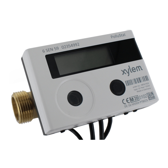
Herunterladen Inhalt Inhalt Diese Seite drucken

Werbung

Verfügbare Sprachen
  • DE

Verfügbare Sprachen

  • DEUTSCH, seite 1
DE FR ES IT EN
Bedienungsanleitung Kommunikationsschnittstellen / Mode d'emploi Interfaces de communication /
Manual de instrucciones Interfaces de comunicación / Manuale d'uso Interfacce di comunicazione /
Operating Instructions Communication Interfaces:
PolluStat & PolluTherm F
Übersicht Schnittstellen und Optionen /
Interfacce e optional / Overview Interfaces and Options:
1.1 Optische (Infrarot-)Schnittstelle / Interface optique (infrarouge) / Interfaz óptica / Interfaccia ottica a infrarossi / Optical
(infrared) interface
Optional / en option / opcional / opzionale / optional
1.2 M-Bus
1.3 Modbus
1.4 Kabellose Schnittstellen/ Interfaces radio sans fil/ Interfaces inalámbricas / Interfacce wireless / Wireless Interfaces
1.4.1 wireless M-Bus
1.4.2 LoRaWAN
1.5 Drei zusätzliche Impulseingänge / Trois entrées d'impulsions supplémentaires / Tres entradas de impulsos adicionales /
Ingressi impulsi aggiuntivi / Three additional pulse inputs
1.6 Ein Impulsausgang potenzialfrei / Une sortie d'impulsions sans potentiel / Una salida de impulsos de libre potential / Uscita
impulsi a potenziale libero / One potential-free pulse output
1.7 Zwei Impulsausgänge potenzialfrei / Deux sorties d'impulsions sans potentiel / Dos salidas de impulsos de libre de
potencial / Uscite impulsi a potenziale libero / Two potential-free pulse outputs
Page 1 of 58
1080619050 / MH 4310 INT5
Aperçu
Interfaces et options / Resumen Interfaces y opciones / Panoramica
2021_07_05
V 0001
Technische Änderungen und Irrtümer vorbehalten.

Werbung

Inhaltsverzeichnis
loading

Inhaltszusammenfassung für Xylem Sensus PolluStat

  • Seite 1 DE FR ES IT EN Bedienungsanleitung Kommunikationsschnittstellen / Mode d'emploi Interfaces de communication / Manual de instrucciones Interfaces de comunicación / Manuale d’uso Interfacce di comunicazione / Operating Instructions Communication Interfaces: PolluStat & PolluTherm F Übersicht Schnittstellen und Optionen / Aperçu Interfaces et options / Resumen Interfaces y opciones / Panoramica Interfacce e optional / Overview Interfaces and Options:...
  • Seite 2: Zusätzliche Technische Spezifikationen

    Bedienungsanleitung Kommunikationsschnittstellen PolluStat & PolluTherm F 1 Schnittstellen und Optionen 1.1 Optische (Infrarot-)Schnittstelle Zur Kommunikation mit der optischen Schnittstelle ist ein optischer Auslesekopf nötig. Der Auslesekopf und eine geeignete Konfigurations-Software sind optional erhältlich. Die optische (Infrarot-)Schnittstelle wird durch das automatische Senden eines Vorspanns (nach EN 13757-3) aktiviert. Baudrate: 2.400 Bd.
  • Seite 3 1.2.3 Technische Daten M-Bus Primäradresse 0 (Werkseinstellung); 1 - 250 (konfigurierbar) Baudrate 2400; 300 Länge Anschlussleitung Anzahl der möglichen Auslesungen unbegrenzt Aktualisierungsrate der Daten 120 s; bei Verwendung des Netzteils 2 s 1.3 Modbus RTU (optional) Das Modbus RTU Modul ist eine galvanisch getrennte Schnittstelle zur Übertragung von Zählerdaten (Absolutwerte). Das Modul ist für die Verwendung mit PolluStat-Wärmezählern und PolluTherm F-Rechnern ausgelegt, um sie über den EIA-485-Kanal mit dem Modbus RTU-Netzwerk zu verbinden.
  • Seite 4: Aktivierung Der Funk-Schnittstelle

    1.4.1.1 Technische Daten Funk Betriebsfrequenz 868 MHz Sendeleistung bis zu 14 dBm Protokoll wireless M-Bus in Anlehnung an die EN 13757-3, -4 Wahlweise Betriebsart S1 / T1 / C1 Telegramme kurzes Telegramm konform für AMR (OMS- langes Telegramm für Walk-by-Auslesung: Spec_Vol2_Primary_v301 und _v402): Energie (Wärme-/Kälteenergie, o Energie (Wärme-/Kälteenergie,...
  • Seite 5: Technische Daten

    1.4.1.4 Nachträgliche Aktivierung der Funk-Verschlüsselung Die AES-Verschlüsselung kann auch nachträglich aktiviert werden. Dies kann auf zwei Arten geschehen: a) Die Verschlüsselung kann mit dem Taster aktiviert werden. Mit langem Tastendruck bis in die Anzeigenschleife „6“ (Modulschleife) umschalten. Dann mit kurzem Tastendruck zur 3ten Anzeige „AES off“ schalten (s. Bild). Um den Editiermodus zu starten, müssen Sie anschließend die Taste noch einmal für 2-3 Sekunden drücken.
  • Seite 6: Drei Zusätzliche Impulseingänge (Optional; Nur In Verbindung Mit M-Bus Oder Funk)

    Pulse input selection Auswahlmöglichkeit zwischen 0-3 Impulseingängen * Das tatsächliche Sendeintervall ist abhängig von der Telegrammart sowie der aktuellen Datenrate. Das Sendeintervall wird entsprechend angepasst, um die eingestellte Batterielebensdauer (EcoMode 10 bzw. 6 Jahre) zu gewährleisten. Nähere Informationen finden Sie im „Manual LoRa Module“. ** Für Impulseingang muss Typ Sensus ausgewählt werden;...
  • Seite 7: Technische Daten Impulseingänge

    1.5.2 Technische Daten Impulseingänge Klasse Impulseingänge IB nach EN 1434-2:2016 Länge Anschlussleitung Versorgungsspannung + 3 V DC Quellenstrom = 1,5 µA Schaltschwelle des Eingangssignals bei U ≥ 2 V High-Level Schaltschwelle des Eingangssignals bei U ≤ 0,5 V Low-Level Endwiderstand 2 MΩ...
  • Seite 8: Ein Impulsausgang Potenzialfrei (Optional)

    Braun IE3+ Weiß IE3┴ 1.6 Ein Impulsausgang potenzialfrei (optional) Über den Impulsausgang potenzialfrei werden Zählimpulse des Zählers ausgegeben. Der Impulsausgang schließt entsprechend der Impulswertigkeit, siehe die Anzeige „Impulswertigkeit Impulsausgang 1“ in Anzeigenschleife „6“ (Modulschleife). Nach dem Einstecken des Moduls erkennt der Zähler Nenngröße und Energieanzeige und stellt damit die Impulswertigkeiten für Energie und Volumen selbstständig ein entsprechend den nachfolgenden Hinweisen.
  • Seite 9: Zwei Impulsausgänge Potenzialfrei (Optional)

    1.7 Zwei Impulsausgänge potenzialfrei (optional) Über die zwei Impulsausgänge potenzialfrei werden Zählimpulse des Zählers ausgegeben. Die Impulsausgänge schließen entsprechend der Impulswertigkeit, siehe die Anzeigen „Impulswertigkeit Impulsausgang 1“ und „Impulswertigkeit Impulsausgang 2“ in Anzeigenschleife „6“ (Modulschleife). Wärmezähler Kältezähler Wärme- / Kältezähler Impulsausgang 1 Wärmeenergie Kälteenergie...
  • Seite 10 Danach den Schraubendreher in einem Winkel von ca. 45° in eine der beiden Öffnungen einführen und vorsichtig nach oben bewegen bis zu einem Winkel von ca. 90° (siehe Bild 2). Die Oberschale des Rechenwerks ist nun auf dieser Seite nicht mehr eingerastet.
  • Seite 11 Zum Entfernen eines Moduls muss beim Aufklappen des Rechenwerks die Oberschale sorgfältig gegen die Rückwand der Unterschale gedrückt werden. Dabei hebeln die hinteren zwei Gehäuse-Verrastungen der Oberschale das Modul von der Platine los (siehe Bild 4). Page 11 of 58 1080619050 / MH 4310 INT5 Stand: 2021_07_05 V 0001 Technische Änderungen und Irrtümer vorbehalten.
  • Seite 12 3 Anzeigemöglichkeiten in der Modulschleife (optional) Ebene 6 / Modulschleife: oder: oder: 3) Anzeige je nach 1) Anzeige des gesteckten 2) Anzeige je nach gestecktem Modul und gestecktem Modul und Moduls (alternativ): Einstellung: Einstellung: 5 = 1 Impulsausgang; wireless M-Bus wireless M-Bus (radio) off/ 8 = Funk mit optional 3 Verschlüsselung (AES) off/...
  • Seite 13 Mode d'emploi Interfaces de communication PolluStat & PolluTherm F Interfaces et options Interface optique (infrarouge) Pour la communication avec l'interface optique, sont nécessaires un optocoupleur et un logiciel de configuration adapté. L'optocoupleur et le logiciel de configuration sont disponibles en accessoire. L'interface infrarouge optique sera activée en envoyant automatiquement un en-tête (conformément à...
  • Seite 14: Réglages Usine

    1.2.3 Caractéristiques techniques de M-Bus Adresse primaire 0 (réglage usine); 1 - 250 (configurable) Vitesse de transmission 2400; 300 Longueur du câble de raccordement Nombre de lectures possibles illimité Actualisation des données 120 s; avec alimentation secteur actualisation toutes les: 2 s Modbus RTU (en option) Le module Modbus RTU est une interface isolée galvaniquement pour la transmission des données du compteur (valeurs absolues).
  • Seite 15 1.4.1.1 Données techniques de radio Fréquence 868 MHz Puissance de jusqu'à 12 dBm transmission Protocole M-bus sans fil basé sur EN 13757-3, -4 Modes S1 / T1 / C1 sélectionnables Télégrammes télégramme court conforme à AMR (OMS-Spec_Vol2_Primary_v301 et _v402): énergie (énergie de chaleur/refroidissement, entrée d'impulsions 1, entrée d´impulsions 2, l'entrée d'impulsions 3), volume total, débit, puissance, message d'indication, température de départ, différence de températures télégramme long pour lecture radio Walk by sur site : énergie (énergie de...
  • Seite 16: Données Techniques

    sortie, chaleur ou chaleur/refroidissement, impulsions, afficheurs) à l'aide du logiciel de lecture Sensus. Le format du télégramme sera ainsi stocké localement dans le PC dans un fichier .xml. Après l'achèvement du mode d'installation, seuls les télégrammes compacts seront transmis. 1.4.1.4 Activation ultérieure du cryptage radio Le cryptage AES peut également être activé...
  • Seite 17 Sélection entrées impulsionnelles Choix entre 0 et 3 entrées * L'intervalle de transmission réel dépend du type de télégramme et du débit de données actuel. L'intervalle de transmission est ajusté en conséquence afin de garantir la durée de vie de la batterie choisie (Mode Eco 10 ou 6 ans). Vous trouverez plus d'informations dans le "Module LoRa manuel".
  • Seite 18: Possibilités De Configuration

    1.5.2 Données techniques des entrées d'impulsions Classe d’entrée d'impulsions IB conformément à EN 1434-2:2016 Longueur du câble de raccordement Alimentation en tension + 3 V DC Source de courant = 1,5 µA Seuil d'entrée de haut niveau U ≥ 2 V Seuil d'entrée de bas niveau U ≤...
  • Seite 19 Une sortie d’impulsions sans potentiel (en option) La sortie d’impulsion sans potentiel fournit les valeurs d´impulsions du compteur. La sortie d’impulsions se ferme conformément à la valeur de l'impulsion, voir "valeur d’impulsion de la sortie d'impulsion 1" dans la boucle d'affichage "6" (boucle de module).
  • Seite 20 Deux sorties d'impulsions sans potentiel (en option) Les sorties d’impulsions sans potentiel fournissent des impulsions du compteur. Les sorties d'impulsions se ferment conformément à la valeur de l'impulsion, voir "valeur d’impulsion de la sortie d'impulsion 1" et "valeur d’impulsion de la sortie d'impulsion 2" dans la boucle d'affichage "6" (boucle de module). Compteur de Compteur de Compteur de...
  • Seite 21 Ensuite, introduire le tournevis dans l'une des deux ouvertures à un angle d'env. 45° et le soulevez prudemment jusqu'à env. 90° (voir image 2). La partie supérieure du boîtier du calculateur n'est alors plus verrouillée de ce côté. Répétez cette opération avec l'autre ouverture.
  • Seite 22 Pour retirer un module, ouvrir le calculateur comme décrit ci-dessus. Tout en ouvrant le calculateur, pressez méticuleusement l´arrête supérieure du couvercle contre l´arrête supérieur du boitier (partie noire). Ainsi, les deux fixations à l´arrière du couvercle soulèvent le module de la platine (voir image 4). Page 22 of 58 1080619050 / MH 4310 INT5 Stand: 2021_07_05 V 0001...
  • Seite 23 Affichage de la boucle du module (en option) Niveau 6 / Boucle du module: oder: oder: 3) Affichage en fonction 2) Affichage en fonction 1) Affichage du module du module branché et de du module branché et de branché (alternatif): la configuration: la configuration: 5 = 1 sortie d´impulsion;...
  • Seite 24 Manual de instrucciones Interfaces de comunicación PolluStat & PolluTherm F 1 Interfaces y opciones 1.1 Interfaz óptica (infrarroja) Para la comunicación con la interfaz óptica es necesario un optoacoplador y un software de configuración adecuado. El optoacoplador y el software de configuración están disponibles como accesorios.
  • Seite 25: Ajuste De Fábrica

    1.2.3 Datos técnicos M-Bus Dirección primaria 0 (ajuste de fábrica); 1 - 250 (configurable) Tasa de baudios 2400; 300 Longitud del cable de conexión Número de lecturas posibles ilimitado Actualización de datos 120 s; utilizando una fuente de alimentación: 2 s 1.3 Modbus RTU (opcional) El módulo Modbus RTU es una interfaz aislada galvánicamente para la transmisión de datos del contador (valores absolutos).
  • Seite 26 1.4.1 Interfaz radio inalámbrica M-Bus EN 13757-3, -4 (opcional) La interfaz de radio es para la transmisión de datos del contador (valores absolutos). 1.4.1.1 Datos técnicos radio Frecuencia 868 MHz Potencia de transmisión hasta 12 dBm Protocolo M-Bus inalámbrico basado en EN 13757-3, -4 Modos seleccionables S1 / T1 / C1 Telegrama corto en conformidad con AMR (OMS-Spec_Vol2_Primary_v301 y _v402):...
  • Seite 27: Especificaciones Técnicas

    b) La función radio también se puede activar mediante el software “Device Monitor”. Este software se puede pedir por separado como una opción. La función radio sólo se puede desactivar mediante el software “Device Monitor”. Después de la activación de la función radio o la modificación de los parámetros de radio, el contador permanece en modo de instalación durante 60 minutos.
  • Seite 28 1.4.2.2 LoRa- Configuración del módulo La configuración es posible con la ayuda del Device Monitor o la aplicación OTC. Parámetros Ajustes posibles Ajuste de fábrica Power mode Active Inactive Inactive Configuration Lock Open Open Locked Synchronize meter time Activation type OTAA OTAA EcoMode...
  • Seite 29 1.5 Tres entradas de impulsos adicionales (opcional, sólo en combinación con M-Bus o radio) Con esta opción, se pueden leer instrumentos adicionales con salidas de impulsos a través de la interfaz óptica, M-Bus o radio. Información general sobre las entradas de impulsos: Deben cumplirse todas las normas técnicas reconocidas y las disposiciones legales pertinentes.
  • Seite 30: Posibilidades De Configuración

    1.5.5 Posibilidades de configuración Valor del impulso Unidades litros / kWh / impulso sin unidad litros / kWh / impulso sin unidad litros / kWh / impulso sin unidad litros / kWh / impulso sin unidad litros / kWh / impulso sin unidad litros / kWh / impulso sin unidad 1000 litros / kWh / impulso sin unidad...
  • Seite 31 qp 3,5 m3/h 10 kWh/pulso 10 Mcal/pulso 10 MJ/pulso 10 MMBTU/pulso qp 6 m3/h 10 kWh/pulso 10 Mcal/pulso 10 MJ/pulso 10 MMBTU/pulso qp 10 m3/h 10 kWh/pulso 10 Mcal/pulso 10 MJ/pulso 10 MMBTU/pulso 1.6.1 Asignación de los conexiones del cable de 4 hilos Color Conexión Amarillo...
  • Seite 32 2 Reequipamiento de una interfaz de comunicación adicional Al instalar el módulo de ampliación, se deben tener en cuenta los requisitos ESD según EN 61340-5-1. En el lugar de instalación del contador significa esto, que se debe utilizar una correa de muñeca ESD con resistencia 1-MΩ integrada, que se debe conectar en un lugar adecuado: ¡Se trata de una tubería conectada a tierra o - sólo con el adaptador adecuado! - el contacto a tierra de una toma de corriente de un enchufo tipo Schuko.
  • Seite 33 El módulo de interfaz debe conectarse en el lado derecho de la placa de circuito impreso (ver imagen 3). Los cables del módulo se introducen a través de los conductos de cable en el extremo derecho de la calculadora después de retirar los ojales ciegos. Cierra la calculadora.
  • Seite 34 3 Opciones de visualización en el lazo del módulo (opcional) Nivel 6 / Lazo del módulo: oder: oder: 2) Pantalla dependiendo del 3) Pantalla dependiendo del 1) Visualización del módulo módulo enchufado y la módulo enchufado y la enchufado configuración: configuración: (alternativamente): 5 = 1 Salida de impulsos;...
  • Seite 35: Specifiche Tecniche Aggiuntive

    Manuale d’uso Manuale d’uso “Interfacce di comunicazione PolluStat & PolluTherm F” 1 Interfacce e optional Interfaccia ottica (a infrarossi) Per la comunicazione con l’interfaccia ottica a infrarossi sono necessari una testina ottica e un software di configurazione adatto (forniti su richiesta). L’interfaccia ottica viene attivata dall’invio automatico di un header (conforme alla norma EN 13757-3).
  • Seite 36 1.3 Modbus RTU (opzionale) Il modulo Modbus RTU è è un’interfaccia per la trasmissione dei dati del contatore (valori assoluti). È dotato di separazione galvanica. È progettato per essere utilizzato con tutti i calorimetri PolluStat e le unità elettroniche PolluTherm F collegando il modulo alla rete utilizzando il canale EIA-485.
  • Seite 37 1.4.1.2 Configurazione dell’interfaccia radio Parametro Impostazioni disponibili Impostazioni di fabbrica (Vita utile stimata della batteria: 10 anni) Modo di trasmissione S1/T1/C1; unidirezionale T1;unidirezionale Periodo di trasmissione 00:00-24:00 8:00-18:00 Intervallo di trasmissione 10 secondi-240 minuti 120 secondi (misuratori di energia termica per applicazioni di riscaldamento) Giorni della settimana Lunedì-domenica...
  • Seite 38: Dati Tecnici

    1.4.2 Interfaccia LoRaWAN L’interfaccia LoRaWAN trasmette i dati del contatore (valori assoluti). 1.4.2.1 Dati tecnici Caratteristiche radio Frequenza 868 MHz Frequenza 868 MHz Potenza in uscita 14 dBm Potenza in uscita 14 dBm Sensibilità ricevitore -135 dBm Sensibilità ricevitore -135 dBm Caratteristiche LoRaWAN Classe dispositivo Classe A, Bidirezionale...
  • Seite 39 Tramite il menu del calorimetro; Premere e tenere premuto il pulsante per visualizzare il circuito "6" (= circuito del modulo; cfr. capitolo 3 Visualizzazione del circuito del modulo (opzionale)), quindi passare al secondo circuito con una breve pressione del pulsante – 6-02 – “EnA oFF” (cfr. immagine). Per attivare la modalità...
  • Seite 40 1.5.3 Compatibilità degli ingressi impulsi (classe IB) e delle uscite impulsi (classe OA) Classe IA Classe IB Classe IC Classe ID Classe IE Classe OA Sì Sì Sì Classe OB Sì Sì Sì Classe OC Sì Sì Classe OD Sì Classe OE Sì...
  • Seite 41 1.6 Uscita impulsi a potenziale libero (su richiesta) L’uscita impulsi a potenziale libero emette gli impulsi del contatore. L’uscita impulsi si chiude in base al valore dell’impulso, v. Valore impulso uscita impulsi 1 nel menù 6/menù delle interfacce. Misuratore di Misuratore di Misuratore di energia termica per applicazioni di...
  • Seite 42 1.7 Uscite impulsi a potenziale libero (su richiesta) Le due uscite impulsi a potenziale libero emettono gli impulsi del contatore. Le uscite impulsi si chiudono in base al valore dell’impulso, v. Valore impulso uscita impulsi 2 nel menù 6/menù delle interfacce. Misuratore di Misuratore di Misuratore di energia termica per...
  • Seite 43 Con il cacciavite inclinato di circa 45° sollevare delicatamente la linguetta verso l’alto a 90° (v. figura sotto). Ora la cover è sganciata su un lato. Ripetere l’operazione nell’altro foro e rimuovere la cover. Installare l’interfaccia sul lato destro della scheda dell’unità elettronica (v. figura sotto). Rimuovere i tappi ciechi dei passacavi che si trovano a destra (tenendo l’unità...
  • Seite 44 Per rimuovere l’interfaccia aprire la cover come illustrato nella figura sotto: sollevarla da un lato e, contemporaneamente, esercitare una leggera pressione sull’altro lato. In questo modo la linguetta (A) farà da leva e solleverà l’interfaccia. Ora è possibile rimuovere l’interfaccia (v. figura sotto). 3 Menù...
  • Seite 45: Optical (Infrared) Interface

    Operating Instructions Communication Interfaces PolluStat & PolluTherm F 1 Interfaces and Options 1.1 Optical (infrared) interface For communication with the optical interface an optocoupler and a suitable configuration software are necessary. The optocoupler and the configuration software are available as accessory equipment. The optical infrared interface will be activated by automatically sending a header (according to EN 13757-3).
  • Seite 46: Default Factory Settings

    1.2.3 Technical data M-Bus Primary address 0 (factory setting); 1 - 250 (configurable) Baud rate 2400; 300 Connecting cable length Number of possible read-outs unlimited Refresh of data 120 s; using a power pack: 2 s 1.3 Modbus RTU (optional) The Modbus RTU Module is a galvanically isolated interface for the transmission of meter data (absolute values).
  • Seite 47 1.4.1.1 Technical data radio Frequency 868 MHz Transmission power up to 12 dBm Protocol wireless M-Bus based on EN 13757-3, -4 Selectable modes S1 / T1 / C1 short telegram in conformity to AMR (OMS-Spec_Vol2_Primary_v301 and _v402): Telegrams energy (heat/cooling energy, pulse input 1 to pulse input 3), total volume, flow, power, information message, outlet flow temperature, temperature difference long telegram for walk-by read-out: energy (heat/cooling energy, pulse input 1 to pulse input 3), total volume, information message, 15 monthly or 30 semimonthly values...
  • Seite 48: Technical Data

    1.4.1.4 Later activation of the radio encryption The AES encryption can also be activated later. It can be activated as follows: a) The encryption can be activated by pressing the push-button. Press the push-button until you change to the display loop “6” (module loop). Then change with a brief keystroke to the 3rd item “AES off“...
  • Seite 49: Three Additional Pulse Inputs (Optional; Only In Conjunction With M-Bus Or Radio)

    * The actual transmission interval depends on the type of telegram and the current data rate. The transmission interval is adjusted accordingly in order to guarantee the set battery life (Eco Mode 10 or 6 years). You can find more information in the „Manual LoRa Module“.
  • Seite 50 Low level input threshold U ≤ 0,5 V Pull-up resistor 2 MΩ Pulse length ≥ 100 ms Pulse frequency ≤ 5 Hz 1.5.3 Possible combinations of the different input (class IB) and output (class OA) devices Class IA Class IB Class IC Class ID Class IE...
  • Seite 51 1.6 One potential-free pulse output (optional) The potential-free pulse output provides counting pulses of the meter. The pulse output closes corresponding to the pulse value, see item „pulse value pulse output 1“ in display loop “6” (module loop). Heat meter Cooling meter Heat/cooling meter Possible settings...
  • Seite 52: Retrofitting Pollustat With An Additional Communication Interface (Optional)

    1.7 Two potential-free pulse outputs (optional) The potential-free pulse outputs provide counting pulses of the meter. The pulse outputs close corresponding to the pulse value, see items „pulse value pulse output 1“ and „pulse value pulse output 2“ in display loop “6” (module loop). Heat meter Cooling meter Heat/cooling meter...
  • Seite 53 Then insert the screwdriver into one of the two openings at an angle of approx. 45° and carefully lift the handle up to approx. 90° (see picture 2). The upper housing piece of the calculator is then no longer latched on this side. Repeat this with the other opening.
  • Seite 54 To remove a module the upper housing piece must be carefully pressed against the rear panel of the lower housing piece during opening the calculator. Thus the two rear snap-fits of the upper housing piece lever out the module of the PC board (see picture 4).
  • Seite 55 3 Display in the Module Loop (Optional) Level 6 / Module Loop: 1) Display of plugged 3) Display depending on 2) Display depending on module (alternatively): plugged module and plugged module and setup: setup: 5 = 1 pulse output; 8 = wireless M-Bus + 3 radio encryption (AES) off;...
  • Seite 56 Page 56 of 58 1080619050 / MH 4310 INT5 Stand: 2021_07_05 V 0001 Technische Änderungen und Irrtümer vorbehalten.
  • Seite 57 Fabbricante/ Manufacturer/ Fabricant/ Producent Sensus Sensor GmbH Rudolf-Diesel-Str. 24-28 69168 Wiesloch-Baiertal Germany Page 57 of 58 1080619050 / MH 4310 INT5 Stand: 2021_07_05 V 0001 Technische Änderungen und Irrtümer vorbehalten.
  • Seite 58 Sensus/Xylem EMEA & AP Sales Contact Information EMEA Locations Asia Pacific Locations Algeria Morocco China Sensus Metering Systems (Fuzhou) Sensus SPA Sensus Maroc S.A. Co., Ltd. B.P. 02 Route de Batna 23 Lot Beau fruit II #4 & #5 Building Tieling North Road El-Eulma- Wilaya de Sétif, Algeria...

Diese Anleitung auch für:

Sensus pollutherm f

Inhaltsverzeichnis