Werbung
Verfügbare Sprachen
Verfügbare Sprachen
Quicklinks
G e n e r a l i n f o r m a t i o n :
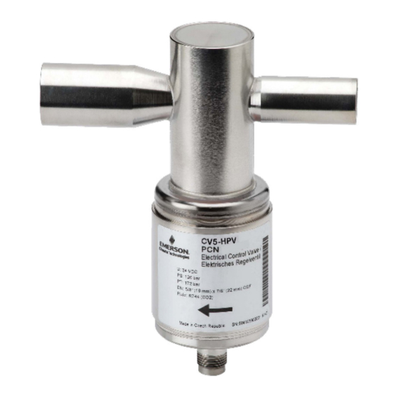
CV are stepper motor driven valves for precise control of
refrigerant mass flow in CO
systems as: (Fig. 1)
2
-
High pressure gas valve (A,)
-
Bypass valve (B),
-
Heat reclaim valve (C),
-
Expansion valves (D),
-
Suction pressure regulating valve (E)
S a f e t y i n s t r u c t i o n s :
• Read operating instructions thoroughly. Failure to
comply can result in device failure, system damage or
personal injury.
• This product is intended for use by qualified personnel
having the appropriate knowledge and skills like trained
according to EN 13313.
• Before opening any system make sure pressure in
system is brought to and remains at atmospheric
pressure.
• Do not release any refrigerant into the atmosphere!
• Do not exceed the specified maximum ratings for
pressure, temperature, and voltage.
• Do not operate system before all cable connections are
completed.
• Do not operate valve connected directly to supply
voltage. Use suitable stepper motor driver.
• Do not operate the valve when the compressor is not
running.
• Do not operate the valve when system is under vacuum
except for closure of valve before refrigerant charging.
• Before installation or service disconnect all voltages
from system and device.
• Do not use any other fluid media without prior approval
of EMERSON. Use of fluid not listed could result in a
change of hazard category of product and consequently
change of conformity assessment requirement for
product in accordance with European pressure
equipment directive 2014/68/EU.
• Ensure that design, installation and operation are
according
to
European
standards/regulations.
M o u n t i n g l o c a t i o n / p o s i t i o n : ( F i g . 1 )
HR = Heat Reclaim, GC = Gas Cooler
High pressure gas valve (A), Bypass valve (B), heat reclaim
valve (C), Suction pressure valve (E):
- The
motor
needs
to
be
pointed
downward.
- The valve must be protected against
contaminants by an upstream filter or
strainer with mesh size 100 µm or
smaller, which should be replaced or
cleaned after first 24 hours of full system
operation.
Expansion valve (D):
- For best result, locate the valve as close as possible to
the distributor or inlet of evaporator.
-
Install a sight glass as well as a filter drier before the
valve.
-
The motor
needs to be
pointed
between
downward to
sideways.
T e c h n i c a l D a t a :
Type
Maximum allowable pressure PS / Factory Test Pressure PT
Max. operating pressure difference MOPD
Operating temperature
Nominal Supply Voltage U / Operating (moving) current peak
Holding current peak
Number of steps / Frequency
Stepping mode / Waveform
Winding resistance per phase /Insulating resistance
Compatibility
Dimensions
Marking
Emerson Climate Technologies GmbH
Pascalstrasse 65 I 52076 Aachen I Germany
O P E R A T I N G I N ST RU C T I O N S
High Pressure Valves Series CV4-7
-
Check for sufficient refrigerant charge/ subcooling and
make sure no flash gas is present at the inlet of valve
before attempting to check valve operation.
-
Allow enough space when placing valve to mount plug as
shown in Fig. 6.
I n s t a l l a t i o n :
• Direction of refrigerant flow must match with arrow on the
label
WARNING:
• All valves are delivered at half open. Do not charge
system before closing of bypass valve (B) and
expansion valve (D). See operating instruction of
used driver/controller.
• The interior parts of valve must be protected against
moisture and water at any time. It is not permitted the use
of water, steam or any other solvent to clean the inside of
valve.
I n s t a l l a t i o n - b r a z i n g O D F c o n n e c t i o n s :
c o p p e r p i p i n g : ( F i g . 3 )
•
Perform and consider the brazing joint as per EN 14324.
•
Before and after brazing clean tubing and brazing joints.
•
Minimize vibrations in the piping lines by appropriate
solutions.
•
Do not exceed
the maximum
surface
temperature
of 120 °C!
• Use flux and
silver rod
having a
minimum of
30 % silver.
NOTE: The valve connections are made of stainless steel
and
national
1.4305 contains 0.15...0.35 % sulphur. According to
standards, it is not recommended to apply welding process
for stainless steel 1.4305 with high content of sulphur.
(difficult to weld).
P r e s s u r e T e s t :
After completion of installation, a pressure test must be
carried out as follows:
- according to EN 378 for systems which must comply
with
European
2014/68/EU.
- to maximum working pressure of system for other
applications.
T i g h t n e s s T e s t :
Fig. 2a
Conduct a tightness test according to EN 378-2 with
appropriate equipment and method to identify leakages
from joints and products. The allowable leakage rate must
be according system manufacturer's specification.
WARNING:
• Failure to pressure test or tightness test as described
could result in loss of refrigerant, damage to property
and/or personal injury.
• The tests must be conducted by skilled personnel
with due respect regarding the danger related to
pressure.
Fig. 2b
24 VDC / 625 mA
750 Steps / 500 Hz
14 Ω ± 10 % / > 20 MΩ
Out of Scope of PED
(no CE Marking required)
www.climate.emerson.com/en-gb
pressure
equipment
directive
CV4-HPV
CV5-HPV / CV6-HPV
Inlet: –50 °C... +100 °C / Outlet: -100 °C...+100 °C
100 mA
750 Steps / 500 Hz
Fluid group II:
CV4/5/6-HPV:
E l e c t r i c a l c o n n e c t i o n :
WARNING:
• Entire electrical connections have to comply with
local regulations.
• Improper wiring will result wrong direction of rotation
or no rotation of stepper motor.
• Ensure that the cables are mounted without tension;
always leave the cable a bit loose.
• Ensure that cables are not mounted near sharp edges.
• Do not bend or mechanically stress the cable outlet,
maintain a clearance of 20 mm to neighboring parts.
• Installation plug-valve
• Prewired plug and cable assembly is ready for
connection to the valve.
• There
is
no
specific
requirement for positioning
of plug on pins.
1. Push the plug on pins on
top of the valve.
2. Rotate the nut one turn in
clockwise
direction
push the plug.
3. Repeat this procedure until the plug is tightened.
• Ensure, that the plug (with cable) is correctly placed
and tighten.
Wiring / Mounting to driver/Controller:
• See the wiring diagram of applied driver/controller.
O p e r a t i o n :
See operating instructions of applied electronic driver/
controller.
S e r v i c e / M a i n t e n a n c e :
• Disconnect electrical power before service.
• Disconnection of electrical plug from device only when the
power is switched off.
• For motor check, remove
cable plug from valve.
Fig. 3
Use an ohmmeter with
suitable range. Measure
windings resistance per
phase at opposite placed
pins acc. Fig. 5 and data
as in the table below.
• CV has capability of positive shut-off when it is driven to
fully close position (as long as inlet pressure is 0.5 bar
above outlet pressure).
• CV can replace defective CX4-6, under consideration by
replacing driver EXD-U01 to EXD-U02. For third party
driver /controller, electrical operating parameter settings
must be adapted. (see Technical data table).
130 bar / 186 bar
70 bar
24 VDC / 800 mA
300 mA
Full step
10 Ω ± 10 % / > 20 MΩ
R744
See Fig. 6
(No. MP604),
OI_CV4-7_A1_EN_DE_FR_ES_IT_RU_Rev04_866918.docx
EN
and
Fig. 4
Fig. 5
CV7-HPV
6400 Steps / 500 Hz
Date: 30.05.2022
Werbung

Verwandte Anleitungen für Emerson CV4-7 Serie


Inhaltszusammenfassung für Emerson CV4-7 Serie
- Seite 1 • Do not use any other fluid media without prior approval silver rod • Disconnect electrical power before service. of EMERSON. Use of fluid not listed could result in a having a • Disconnection of electrical plug from device only when the...
- Seite 2 Bauteil spannungsfrei zu schalten. festsitzt. Fig. 4 • Vor und nach dem Löten sind die Lötstellen zu reinigen. • Es dürfen nur von EMERSON freigegebene Medien • Stellen Sie sicher, dass der Stecker (mit Kabel) korrekt • Vibrationen Rohrleitungen sind durch eingesetzt werden.
- Seite 3 • Ne pas utiliser un autre fluide que ceux indiqués sans • Se reporter au mode d’emploi du module ou du des équipements l’approbation obligatoire d’EMERSON. L'utilisation d'un régulateur électronique. appropriés. fluide non approuvé peut conduire à: Le changement de •...
- Seite 4 • No use ningún fluido que no haya sido previamente temperatura /controlador. aprobado por EMERSON. El uso de sustancias no superf. de aprobadas puede dar lugar a: un cambio en la categoría O p e r a c i ó n : 120 °C!
- Seite 5 • Non utilizzare altri fluidi senza la previa approvazione di • Ridurre il più possibile le vibrazioni sulle tubazioni componente. EMERSON. L’uso di refrigeranti non indicati nelle utilizzando soluzioni Cablaggio / Montaggio del connettore: specifiche potrebbe causare: Modifiche nella categoria appropriate.
-
Seite 6: Руководство По Эксплуатации
10 Ом ± 10 % / > 20 МОм Совместимо с Группа жидкостей II R744 Pазмеры см. рис. 6 Не подпадает под действие PED CV4/5/6-HPV: Mаркировка (маркировка CE не требуется), (№. MP604) Emerson Climate Technologies GmbH www.climate.emerson.com/en-gb Date: 30.05.2022 Pascalstrasse 65 I 52076 Aachen I Germany OI_CV4-7_A1_EN_DE_FR_ES_IT_RU_Rev04_866918.docx... - Seite 7 (mm/ мм) (802059) (802056) (802057) (802058) Ø A 3/8” 5/8” (16) 7/8” (22) 1-1/8” Ø F (ODF) 5/8” (16) 7/8” (22) 1-1/8” 1-1/8” Ø G Emerson Climate Technologies GmbH www.climate.emerson.com/en-gb Date: 30.05.2022 Pascalstrasse 65 I 52076 Aachen I Germany OI_CV4-7_A1_EN_DE_FR_ES_IT_RU_Rev04_866918.docx...