Inhaltsverzeichnis
Werbung
Verfügbare Sprachen
Verfügbare Sprachen
Quicklinks
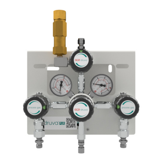
MANIFOLD
ENTSPANNUNGSSTATION
M – MANIFOLD | P-PUR | L – LOW FLOW | H0 – HIGH PRESSURE |
HE – LOW PRESSURE WITH EPDM RELIEF VALVE |
M – MANUAL CHANGE OVER | S – SINGLE STAGE
M – MANIFOLD | S-SST | L – LOW FLOW | H0 – HIGH PRESSURE |
HE – LOW PRESSURE WITH EPDM RELIEF VALVE |
M – MANUAL CHANGE OVER | S – SINGLE STAGE
INSTRUCTION FOR USE
GEBRAUCHSANLEITUNG
IMPORTANT!
Read carefully before use! Keep the manual for future consultation!
WICHTIG!
Vor Gebrauch sorgfältig lesen!
Bewahren Sie die Gebrauchsanweisung für späteres Nachschlagen auf!
GCE CENTRAL GAS SYSTEMS
EN
DE
Werbung
Inhaltsverzeichnis
Fehlerbehebung

Verwandte Anleitungen für GCE druva MPLH0MSS

Inhaltszusammenfassung für GCE druva MPLH0MSS
- Seite 1 GCE CENTRAL GAS SYSTEMS MANIFOLD ENTSPANNUNGSSTATION M – MANIFOLD | P-PUR | L – LOW FLOW | H0 – HIGH PRESSURE | HE – LOW PRESSURE WITH EPDM RELIEF VALVE | M – MANUAL CHANGE OVER | S – SINGLE STAGE M –...
-
Seite 2: Inhaltsverzeichnis
......................................4 1.1 information about this instructions manual ........................4 1.2 Information about this manifold ............................4 1.2.1 MPLH0MSS / MSLH0MSS, MPLHEMSS / MSLHEMSS ..................6 1.2.2 MPLH0MSP / MSLH0MSP, , MPLHEMSP / MSLHEMSP ..................6 1.2.3 MSLH0MSE, MSLHEMSE ............................6 1.3 explanation of symbols ................................. - Seite 3 5 Transport, packaging and storage ........................23 5.1 Safety information for transportation ..........................23 5.2 Transport inspection ................................23 5.3 Packaging .....................................23 5.4 Storage ....................................23 6 Installation and initial start-up ..........................24 6.1 Safety notes for installation and initial start-up ......................24 6.2 Preparation ...................................24 6.3 Installation .....................................24 6.4 Required qualifications for initial start-up and cylinder changing ................24 6.5 Initial Start Up..................................25...
-
Seite 4: General
ENGLISH INSTRUCTION FOR USE: MANIFOLD 1. GENERAL 1.1. INFORMATION ABOUT THIS INSTRUCTIONS MANUAL This instruction is only intended for use with manifold product type: • MPLH0MS, MSLHEMS – Single stage manifold with manual change over for two cylinders • MSLH0MS, MSLHEMS – Single stage manifold with manual change over for two cylinders Manifolds of this type are suitable to take gas out of gas cylinder or bundle and reduce the pressure. - Seite 5 AV - Absolute Pressure Regula- • Suitable Gases • Suitable Gases tor with Seat (including their mixtures) (including their mixtures) • High Purity • High Purity • Inert • Inert • Flammable • Flammable • Oxidizing • Oxidizing • Use for O2 •...
-
Seite 6: Mplh0Mss / Mslh0Mss, Mplhemss / Mslhemss
1.2.1. MPLH0MSS / MSLH0MSS, MPLHEMSS / MSLHEMSS This manifold is available in brass chrome plated (MPL…) and stainless steel (MSL…). It consists of the follow- ing components: • Pressure regulator with inlet pressure gauge, outlet pressure gauge and handwheel to regulate outlet pressure •... -
Seite 7: Limitations Of Liability
NOTE! This combination of symbol and signal word indicates a pos- sibly dangerous situation that can cause property and environ- mental damage if not avoided. TIPS AND RECOMMENDATIONS This symbol highlights useful tips and recommendations, to- gether with help for ensuring efficient and trouble-free opera- tion. -
Seite 8: Warranty Provision
1.7. WARRANTY PROVISION The warranty provisions are included in the manufacturer’s general terms and conditions of business. See chapter VI. Warranty Claims. 1.8. CUSTOMER SERVICE GCE GmbH Weyherser Weg 8 DE-36043 Fulda Please do not hesitate to provide us with information and experiences gained through use; we welcome any valuable input that will help to improve our products. -
Seite 9: Operator's Responsibility
ATTENTION! • Risk of injury from environment! There can be malfunctions on component due to condensation and/ or icing. THEREFORE: • Observe suitable temperatures. • Protect component from liquids from outside • Protect component from dust from outside • Protect component from weather conditions •... -
Seite 10: Personnel Requirements
THE FOLLOWING APPLIES IN PARTICULAR: • The operator must be aware of the applicable work safety regulations and must perform a risk assessment to identify risks that may occur as a result of the specific working conditions at the site where the system is operated. -
Seite 11: Training
2.4.3. TRAINING The operator must train the staff at regular intervals. A training log must be maintained for purposes of better tracking and must contain the following information, at least: • Date of training • Names of trained staff • Contents of the training session •... -
Seite 12: Behavior In Case Of Fire Or Accident
2.6. BEHAVIOR IN CASE OF FIRE OR ACCIDENT PREVENTIVE MEASURE • Always be prepared for fires and accidents! • Always keep first aid equipment (kit, blankets, etc.) and fire extinguishing equipment in working order and close to hand. • Familiarize the staff with accident reporting, first aid and emergency procedures. •... -
Seite 13: Technical Specifications
3. TECHNICAL SPECIFICATIONS 3.1. FLOW SCHEME – MPLH0MSS/ MSLH0MSS, MPLHEMSS/ MSLHEMSS 1 – GAS CYLINDER 2 – COIL/HOSE 3 – CHECK VALVE 4 – SHUT-OFF VALVE (3XIN, 1XOUT) 5 – PRESSURE REGULATOR 6 – SHUT-OFF VALVE (1XIN, 3XOUT) 7 – RELIEF VALVE 8 –... -
Seite 14: Dimension Sheet - Mplh0Mss/ Mslh0Mss, Mplhemss/ Mslhemss
3.2. DIMENSION SHEET – MPLH0MSS/ MSLH0MSS, MPLHEMSS/ MSLHEMSS Grounding 14/64... -
Seite 15: Flow Scheme - Mplh0Msp/ Mslh0Msp, Mplhemsp/ Mslhemsp
3.3. FLOW SCHEME – MPLH0MSP/ MSLH0MSP, MPLHEMSP/ MSLHEMSP 1 – GAS CYLINDER 2 – COIL/HOSE 3 – CHECK VALVE 4 – SHUT-OFF VALVE (3XIN, 1XOUT) 5 – PURGE OUTLET VALVE 6 – PRESSURE REGULATOR 7 – RELIEF VALVE 8 – SHUT-OFF VALVE (1XIN, 3XOUT) 9 –... -
Seite 16: Dimension Sheet - Mplh0Msp/ Mslh0Msp, Mplhemsp/ Mslhemsp
3.4. DIMENSION SHEET – MPLH0MSP/ MSLH0MSP, MPLHEMSP/ MSLHEMSP Grounding 16/64... -
Seite 17: Flow Scheme - Mslh0Mse, Mslhemse
3.5. FLOW SCHEME – MSLH0MSE, MSLHEMSE 1 – GAS CYLINDER 2 – COIL/HOSE 3 – SHUT-OFF VALVE (3XIN, 1XOUT) 4 – PURGE OUTLET VALVE 5 – PRESSURE REGULATOR 6 – PRESSURE REGULATOR 2nd STAGE 7 – RELIEF VALVE 8 – SHUT-OFF VALVE (1XIN, 3XOUT) 9 –... -
Seite 18: Dimension Sheet - Mslh0Mse, Mslhemse
3.6. DIMENSION SHEET – MSLH0MSE, MSLHEMSE Grounding 18/64... -
Seite 19: General Information
3.7. GENERAL INFORMATION Information MPLH0MSS MSLH0MSS MPLHEMSS MSLHEMSS max. Weight [kg] 5,92 5,74 5,92 5,74 Length [mm] Depth [mm] Height [mm] Information MPLH0MSP MSLH0MSP MPLHEMSP MSLHEMSP MSLH0MSE MSLHEMSE max. Weight [kg] 6,82 6,61 6,82 6,61 8,35 8,35 Length [mm] Depth [mm] Height [mm] 3.8. -
Seite 20: Set-Up And Function
4. SET-UP AND FUNCTION 4.1. OVERVIEW – MPLH0MSSSU, MPLHEMSSSU – FULL VERSION 4.2. OVERVIEW – MSLH0MSSSU, MSLHEMSSSU – FULL VERSION 20/64... -
Seite 21: Overview - Mplh0Mspsu, Mplhemspsu - Full Version
4.3. OVERVIEW – MPLH0MSPSU, MPLHEMSPSU – FULL VERSION 4.4. OVERVIEW – MSLH0MSPSU, MSLHEMSPSU – FULL VERSION 21/64... -
Seite 22: Overview - Mslh0Msess - Full Version
4.5. OVERVIEW – MSLH0MSESU, MSLHEMSESU – FULL VERSION 4.6. BRIEF DESCRIPTION MPLH0MS / MSLH0MS, MPLHEMS / MSLHEMS With the manifold type MPLH0M, MPLHEM… (material: brass chrome plated) an industrial, non-toxic and non-corrosive gas or gas mixture, which is stored inside gas cylinder or bundle with over pressure can be reduced from maximum 300 bar tubing pressure (3 bar, 6 bar, 10 bar, 14 bar, 28 bar, 50 bar, 100 bar, 200 bar). -
Seite 23: Transport, Packaging And Storage
5. TRANSPORT, PACKAGING AND STORAGE TIPS AND RECOMMENDATIONS! • The installation and start- up of this gas supply panel is normally done by the supplier or by authorized personnel. • Even though there can be some users or maintenance personnel who care about the packaging. The fol- lowing notes should be observed accordingly. -
Seite 24: Installation And Initial Start-Up
TIPS AND RECOMMENDATIONS! • Some packages may bear labels with storage information that extends beyond these requirements. These notes should be observed accordingly. 6. INSTALLATION AND INITIAL START-UP 6.1. SAFETY NOTES FOR INSTALLATION AND INITIAL START-UP STAFF Installation and initial start-up of the system may only be performed by qualified staff. 6.2. -
Seite 25: Initial Start Up
• Before first start-up check type label, if the manifold is suitable for the provided purpose (gas, pressure, material, etc.) 6.5. INITIAL START UP • All requirements are fulfilled as on point 6.4 • Manifold is depressurized, handwheel turned completely to left side •... -
Seite 26: Change Empty Gas Cylinder
6.5.4. CHANGE EMPTY GAS CYLINDER NOTE! • MAK- Value (see Technical Rules for Hazardous Substances, TRGS 900) 1. Close cylinder valve 2. Close inlet valve on empty cylinder side 3. Open outlet purge valve to depressurize coil/ hose. 4. MPLH0MSP/ MSLH0MSP, MPLHEMSP/ MSLHEMSP:: purge with process gas purging (see point 6.5.1) MSLH0MSE, MSLHEMSE: purge with inert gas purging (see point 6.5.2) 5. -
Seite 27: Maintenance Work
NOTE! • Please contact the manufacturer if you have any questions relating to maintenance works and intervals (see 1.8 for contact details). Interval Maintenance work Personal Weekly Check all components visually Competent Person (TRBS 1203) Every year Checking function & tightness, Competent Person (TRBS 1203) check for all safety relevant com- ponents... -
Seite 28: Troubleshooting
9. TROUBLESHOOTING The following section describes possible causes of malfunction and how to eliminate them. If malfunctions occur with increasing regularity, shorten the maintenance intervals to reflect the actual load. If malfunctions occur that cannot be eliminated with the following help, please contact the manufacturer (see section 1.8 for contact details). - Seite 29 Description Reason Solution Valve Cylinder Line Regulator Regulator Supply Panel Slight drop of Difference No failure, nor- outlet pressure between flow mal operating pressure (with state gas flow) and Zero Pressure (without gas flow) Heavy drop of Required Choose new outlet pressure flow to high pressure...
-
Seite 30: Dismantling And Disposal
Description Reason Solution Valve Cylinder Line Regulator Regulator Supply Panel Icing on pres- Pressure regu- No failure, nor- sure regulator lator withdraw mal operating (NO dew, rain energy from state ATTEN- or snow) environment TION: keep through gas functionality of expansion, lim- contact gauges ited delivery... - Seite 31 In accordance to Article 33 of REACH GCE, s.r.o. as responsible manufacturer shall inform all customers if materials containing 0.1% or more of substances included in the list of Substance of Very High Concern (SVHC). The most commonly used brass alloys used for bodies and other brass components contain 2-3% of lead (Pb), EC no.
- Seite 32 1 Allgemeines ....................................34 1.1 Information zu dieser Anleitung ............................34 1.2 Information zur Entspannungssation ..........................34 1.2.1 MPLH0MSS / MSLH0MSS, MPLHEMSS / MSLHEMSS ..................36 1.2.2 MPLH0MSP / MSLH0MSP, MPLHEMSP / MSLHEMSP..................36 1.2.3 MSLH0MSE, MSLHEMSE ............................36 1.3 Symbolerklärung ................................. 37 1.4 Haftungsbeschränkung ..............................37 1.5 Urheberschutz ..................................38...
- Seite 33 5 Transport, Verpackung und Lagerung ......................54 5.1 Sicherheitshinweise für den Transport ...........................54 5.2 Transport Inspektion ................................54 5.3 Verpackung ..................................54 5.4 Lagerung ....................................55 6 Installation und Erstinbetriebnahme ........................55 6.1 Sicherheitshinweise für die Installation und Erstinbetriebnahme ................55 6.2 Vorbereitungen ...................................55 6.3 Installation .....................................55 6.4 Voraussetzung zur Erstinbetriebnahme........................56 6.5 Erstinbetriebnahme ................................56 6.5.1 Eigengasspülung (MPLH0MSP und MSLH0MSP, MPLHEMSP und MSLHEMSP)) ........56...
-
Seite 34: Allgemeines
DEUTSCH GEBRAUCHSANLEITUNG: ENTSPANNUNGSSTATION 1. ALLGEMEINES 1.1. INFORMATION ZU DIESER ANLEITUNG Diese Anleitung gilt für Entspannungsstationen des Typs: • MPLH0MS, MPLHEMS – einstufige Entspannungsstation mit manueller Umschaltung für zwei Gasflaschen • MSLH0MS, MSLHEMS – einstufige Entspannungsstation mit manueller Umschaltung für zwei Gasflaschen Diese Entspannungsstationen werden verwendet um Gas aus Druckgasbehältern zu entnehmen und zu ent- spannen. - Seite 35 LV - Niederdruck Regler • Verwendbare Gase • Verwendbare Gase Dichtung im Abblasev- (inclusive deren Mischungen) (inclusive deren Mischungen) entilsitz • High Purity • High Purity • Inert • Inert • Brennbar • Brennbar • Brandfördernd • Brandfördernd • • Ätzend •...
-
Seite 36: Mplh0Mss / Mslh0Mss, Mplhemss / Mslhemss
Diese Tabelle erhebt keinen Anspruch auf Vollständigkeit. Bei Fragen und Unklarheiten kontaktieren Sie bitte den Hersteller. Kontaktdaten unter Kapital 1.8. 1.2.1. MPLH0MSS / MSLH0MSS, MPLHEMSS / MSLHEMSS Diese Entspannungstation ist in der Messing verchromtem und in der Edelstahlversion erhältlich. Sie besteht aus folgenden Komponenten: •... -
Seite 37: Symbolerklärung
1.3. SYMBOLERKLÄRUNG SICHERHEITSHINWEISE Sicherheitshinweise sind in dieser Anleitung durch Symbole gekennzeichnet. Die Sicherheitshinweise werden durch Sig- nalworte eingeleitet, die das Ausmaß der Gefährdung zum Ausdruck bringen. GEFAHR! Diese Kombination aus Symbol und Signalwort weist auf eine unmittelbar gefährliche Situation hin, die zum Tod oder zu schweren Verletzungen führt, wenn sie nicht gemieden wird. -
Seite 38: Urheberschutz
Der tatsächliche Lieferumfang kann bei Sonderausführungen, der Inanspruchnahme zusätzlicher Bestellop- tionen oder aufgrund neuester technischer Änderungen von den hier beschriebenen Erläuterungen und Darstellungen abweichen. Es gelten die im Liefervertrag vereinbarten Verpflichtungen, die allgemeinen Ge- schäftsbedingungen sowie die Lieferbedingungen des Herstellers und die zum Zeitpunkt des Vertragsab- schlusses gültigen gesetzlichen Regelungen. -
Seite 39: Bauliche Veränderung An Der Entspannungsstation
WARNUNG! • Gefahr bei Fehlgebrauch! • Fehlgebrauch der Entspannungsstationen kann zu gefährlichen Situationen führen. • Niemals die Entspannungsstationen für Flüssigkeiten verwenden. 2.1.1. BAULICHE VERÄNDERUNG AN DER ENTSPANNUNGSSTATION Ohne schriftliche Genehmigung des Herstellers keine Veränderung, An- oder Umbauten an der Entspan- nungsstation vornehmen. -
Seite 40: Verantwortung Des Betreibers
WARNUNG! • Unfallgefahr durch im System gespeicherte Energie! • Durch falsche Handhabung können drucktragende Teile oder Einzelteile dieser unkontrolliert in Bewe- gung geraten und ernsthafte oder sogar tödliche Verletzungen verursachen. Durch falsche Handhabung kann Gas aus den drucktragenden Teilen austreten und ernsthafte oder sogar tödliche Verletzungen her- vorrufen. -
Seite 41: Personalanforderungen
2.4. PERSONALANFORDERUNGEN 2.4.1. QUALIFIKATIONEN Die verschiedenen in dieser Anleitung beschriebenen Aufgaben stellen unterschiedliche Anforderungen an die Qualifikation der Personen, die mit diesen Aufgaben betraut sind. WARNUNG! • Gefahr bei unzureichender Qualifikation von Personen! • Unzureichend qualifizierte Personen können die Risiken beim Umgang mit dem Gerät nicht einschätzen und setzen sich und andere der Gefahr schwerer oder tödlicher Verletzungen aus. -
Seite 42: Verhalten Bei Feuerausbruch Und Bei Unfällen
ATEMSCHUTZGERÄT, UMLUFT ABHÄNGIG Schutz vor schädlichen Gasen, Dämpfen, Stäuben und ähnlichen Stoffen. Umluft abhängige Atemschutzgeräte müssen eingesetzt werden, wenn ein Über- schreiten der zulässigen Grenzwerte schädlicher Stoffe in der Umgebungsluft nicht ausgeschlossen werde kann. Umluft abhängige Atemschutzgeräte dürfen nur bei einem garantierten Sauerst- offgehalt in der Atemluft von über 17% eingesetzt werden. -
Seite 43: Beschilderung
2.8. BESCHILDERUNG WARNUNG! • Gefahr bei unleserlicher Beschilderung! • Im Laufe der Zeit können Aufkleber und Schilder verschmutzen oder auf andere Weise unkenntlich werden, so dass Gefahren nicht erkannt und notwendige Bedienhinweise nicht befolgt werden können. Dadurch besteht Verletzungsgefahr. • Alle Sicherheits-, Warn- und Bedienungshinweise in stets gut lesbarem Zustand halten. -
Seite 44: Technische Daten
3. TECHNISCHE DATEN 3.1. FLIESSSCHEMA – MPLH0MSS/ MSLH0MSS, MPLHEMSS/ MSLHEMSS 1 – GASFLASCHE 2 – ANSCHLUSSWENDEL / SCHLAUCH 3 – RÜCKSCHLAGVENTIL 4 – ABSPERRVENTIL (3XIN, 1XOUT) 5 – DRUCKREGLER 6 – ABSPERRVENTIL (1XIN, 3XOUT) 8 – ABBLASEVENTIL 9 – SICHERHEITSVENTIL... -
Seite 45: Massblatt - Mplh0Mss/ Mslh0Mss, Mplhemss/ Mslhemss
3.2. MASSBLATT – MPLH0MSS/ MSLH0MSS, MPLHEMSS/ MSLHEMSS Erdung 45/64... -
Seite 46: Fließschema - Mplh0Msp/ Mslh0Msp, Mplhemsp/ Mslhemsp
3.3. FLIESSSCHEMA – MPLH0MSP/ MSLH0MSP, MPLHEMSP/ MSLHEMSP 1 – GASFLASCHE 2 – ANSCHLUSSWENDEL / SCHLAUCH 3 – RÜCKSCHLAGVENTIL 4 – ABSPERRVENTIL (3XIN, 1XOUT) 5 – VENTIL ZUR EIGENGASSPÜLUNG 6 – DRUCKREGLER 7 – ABBLASEVENTIL 8 – ABSPERRVENTIL (1XIN, 3XOUT) 9 – SICHERHEITSVENTIL Optionen dargestellt als gepunktete Linie 46/64... -
Seite 47: Massblatt - Mplh0Msp/ Mslh0Msp, Mplhemsp/ Mslhemsp
3.4. MASSBLATT – MPLH0MSP/ MSLH0MSP, MPLHEMSP/ MSLHEMSP Erdung 47/64... -
Seite 48: Fließschema - Mslh0Mse, Mslhemse
3.5. FLIESSSCHEMA – MSLH0MSE, MSLHEMSE 1 – GASFLASCHE 2 – ANSCHLUSSWENDEL / SCHLAUCH 3 – ABSPERRVENTIL (3XIN, 1XOUT) 4 – AUSGANGSSPÜLVENTIL 5 – DRUCKREGLER 6 – DRUCKREGLER 2.STUFE 7 – ABBLASEVENTIL 8 – ABSPERRVENTIL (1XIN, 3XOUT) 9 – SICHERHEITSVENTIL 10 – EINGANGSSPÜLVENTIL (1XIN, 3XOUT) Optionen dargestellt als gepunktete Linie 48/64... -
Seite 49: Massblatt - Mslh0Mse, Mslhemse
3.6. MASSBLATT – MSLH0MSE, MSLHEMSE Erdung 49/64... -
Seite 50: Allgemeine Angaben
3.7. ALLGEMEINE ANGABEN Angabe MPLH0MSS MSLH0MSS MPLHEMSS MSLHEMSS max. Gewicht[kg] 5,92 5,74 5,92 5,74 Länge [mm] Breite [mm] Höhe[mm] Angabe MPLH0MSP MSLH0MSP MPLHEMSP MSLHEMSP MSLH0MSE MSLHEMSE max. Gewicht[kg] 6,82 6,61 6,82 6,61 8,35 8,35 Länge [mm] Breite [mm] Höhe[mm] 3.8. ANSCHLUSSWERTE... -
Seite 51: Aufbau Und Funktion
4. AUFBAU UND FUNKTION 4.1. AUFBAU – MPLH0MSSSU, MPLHEMSSSU – VOLLVERSION 4.2. AUFBAU – MSLH0MSSSU, MSLHEMSSSU – VOLLVERSION 51/64... -
Seite 52: Aufbau - Mplh0Mspsu, Mplhemspsu - Vollversion
4.3. AUFBAU – MPLH0MSPSU, MPLHEMSPSU – VOLLVERSION 4.4. AUFBAU – MSLH0MSPSU, MSLHEMSPSU – VOLLVERSION 52/64... -
Seite 53: Aufbau - Mslh0Msess, Mslhemsess - Vollversion
4.5. AUFBAU – MSLH0MSESS, MSLHEMSESS – VOLLVERSION 4.6. KURZBESCHREIBUNG MPLH0MS / MSLH0MS, MPLHEMS / MSLHEMS Durch die Entspannungsstationen vom Typ MPLH0M, MPLHEM…(Material: Messing verchromt) wird ein industrielles, nicht giftiges und nicht ätzendes Gas oder Gasgemisch, welches in einem Druckgasbehälter/ Druckgasbehälterbündel unter Überdruck gespeichert ist, von einem maximalen Druck von bis zu 300 bar auf einen Rohrleitungsdruck (3 bar, 6 bar, 10 bar, 14 bar, 28 bar, 50 bar, 100 bar, 200 bar) entspannt. -
Seite 54: Transport, Verpackung Und Lagerung
Die Entwicklung, Fertigung und Produktionsprüfung der o. g. Systeme erfolgte u. a. unter Einhaltung folgen- der Standards: - Druckminderer- ISO 7291 - Ventile- ISO 10297 - Manometer EN 837-1 - Mechanischer Explosionsschutz der Komplettstation- ISO80079-36; IEC 60079-32-1; TRGS 727 5. TRANSPORT, VERPACKUNG UND LAGERUNG TIPPS UND EMPFEHLUNGEN! •... -
Seite 55: Lagerung
5.4. LAGERUNG PACKSTÜCKE UNTER FOLGENDEN BEDINGUNGEN LAGERN: • Nicht im Freien aufbewahren. • Trocken und staubfrei lagern. • Keinen aggressiven Medien aussetzen. • Vor Sonneneinstrahlung schützen. • Mechanische Erschütterungen vermeiden. • Lagertemperatur: 15 bis 35 °C. • Relative Luftfeuchtigkeit: max. 60 %. •... -
Seite 56: Voraussetzung Zur Erstinbetriebnahme
Wellschläuche. Diese ist für den Anschluss an linken und rechten Seite der Entspannungsstation geeignet. Zur Montage der Anschlusswendel/ des Anschlussschlauches an der Entspannungsstation zunächst die Kunststoffkappe von Anschlussgewinde der Wendelleitung/ des Schlauches und der Entspannungsstation entfernen. Bitte darauf achten, dass die mit der Wendel/ dem Schlauch mitgelieferte Flachdichtung in die Überwurfmut- ter eingelegt ist. -
Seite 57: Fremdgasspülung (Mslh0Mse, Mslhemse)
DIE SCHRITTE 4. – 8. MINDESTENS 10X WIEDERHOLEN 6.5.2. FREMDGASSPÜLUNG (MSLH0MSE, MSLHEMSE) Entspannungsstationen MSLH0MSE, MSLHEMSE mit Fremdgasspülung werden eingesetzt, damit vor dem Flaschenwechsel giftiges und/oder ätzendes Gas entfernt werden kann und die Wendelleitung oder der Anschluss-schlauch zum Flaschenwechsel entlastet werden kann. Sicherstellen, dass eine Abblaseleitung angeschlossen ist. -
Seite 58: Prüfungen
GEFAHR! • Druckregler und Leitungen durch Ableiten des Gases über den Verbraucher entspannen. Die Zeiger der Eingangs- und Ausgangsmanometer müssen vollständig auf „0“ stehen. • Gegebenenfalls Eigengas- oder Fremdgasspülung durchführen. • Entsprechende Personenschutzmaßnahmen sind zu treffen. • MAK-Werte beachten. • Es ist unbedingt darauf zu achten, dass die Entspannungsstation nicht über den zulässigen Betriebsdruck hinaus mit Druck beaufschlagt wird. -
Seite 59: Wartungsarbeiten
8.3. WARTUNGSARBEITEN 8.3.1. REINIGUNG HINWEIS! • Reinigungsmittel müssen mit den Materialien, mit denen sie in Berührung kommen, verträglich sein. 8.3.2. VORAUSSETZUNG ZUR WARTUNG VOR BEGINN DER WARTUNG IST ZU PRÜFEN, DASS • Die Gasversorgung unterbrochen und sichergestellt ist. • Die Entspannungsstation drucklos ist. •... - Seite 60 Beschreibung Ursache Lösung Ventile Flaschen- Leitungs- Entspannungs- druckregler druckregler stationen Kein Druckregler Druckregler Durchfluss geschlos- langsam (Eingangs- öffnen manometer Spülventil zeigt Druck an, schließen Ausgangsma- nometer nicht) Kein Durch- Flaschen- Inbetrieb- fluss (beide ventil nahme gemäß Manometer geschlossen Punkt 6. In- zeigen Null) Brauch- stallation und...
- Seite 61 Beschreibung Ursache Lösung Ventile Flaschen- Leitungs- Entspannungs- druckregler druckregler stationen Starker Hinter- Erforderli- Auswahl eines druckabfall chen Durch- neuen Druck- fluss für reglers für Druckregler geforderten zu groß Druck & Durchfluss Starker Hinter- Undichte Prozess- druckabfall Prozess- gasleitung gasleitung überprüfen Ausgangs- Falsche Druckregler...
-
Seite 62: Demontage Und Entsorgung
Beschreibung Ursache Lösung Ventile Flaschen- Leitungs- Entspannungs- druckregler druckregler stationen Eisbildung auf Druckregler Kein Fehler Druckregler entzieht der Normaler Be- (KEIN Tau, Umwelt En- triebszustand Regen oder ergie durch ACHTUNG: Schnee) Gasents- auf Funktion- pannung, alität der Kon- limitierte taktmanom- Lieferleis- eter achten, tung der... -
Seite 63: Entsorgung
10.3. ENTSORGUNG Sofern keine Rücknahme- oder Entsorgungsvereinbarung getroffen wurde, zerlegte Bestandteile der Wied- erverwertung zuführen: Metalle verschrotten. Kunststoffelemente zum Recycling geben. Übrige Komponenten nach Materialbeschaffenheit sortiert entsorgen. Gemäß dem Artikel 33 der REACH-Verordnung verpflichtet sich die Gesellschaft GCE, s.r.o. als verantwor- tungsbewusster Hersteller, alle Kunden darüber zu informieren, wenn die Materialien 0,1% oder mehr der auf der Liste aufgeführten besonders besorgniserregenden Stoffe (SVHC) enthalten. - Seite 64 RUSSIA SWEDEN UNITED KINGDOM POLAND IRELAND GERMANY CZECH REPUBLIC FRANCE HUNGARY ROMANIA UNITED STATES ITALY SPAIN OF AMERICA PORTUGAL CHINA MEXICO INDIA PANAMA Manufacturer: GCE s.r.o. Žižkova 381, 583 01 Chotěboř, Česká republika http://www.gcegroup.com Doc. Nr.: IFU-MXLHXMS; DOI: 2020-01-16; Rev.:01; TI: A5, CB, V1...