Herunterladen Inhalt Inhalt Diese Seite drucken

Werbung

Verfügbare Sprachen
  • DE

Verfügbare Sprachen

  • DEUTSCH, seite 16
L854200251
02/2021 rev 1
CP.B24-SW
UNIONE NAZIONALE COSTRUTTORI
AUTOMATISMI PER CANCELLI, PORTE
SERRANDE ED AFFINI

Werbung

Inhaltsverzeichnis
loading

Inhaltszusammenfassung für Beninca CP.B24-SW

  • Seite 1 L854200251 02/2021 rev 1 CP.B24-SW UNIONE NAZIONALE COSTRUTTORI AUTOMATISMI PER CANCELLI, PORTE SERRANDE ED AFFINI...
  • Seite 3 EXT. BOX 2x12V Battery Charger Battery (Optional) POWER INPUT SELECTION -24V 24Vdc / 500mA max 230Vac 115Vac +24V BLINK LAMP 24Vdc BLINK PHOT STOP P.P. SHIELD X.BE F1 T2A Functions Setup LD1 ON LD2 ON LD3 ON ON/OFF SCA/2°Ch ON/OFF Photo Op ON/OFF P.P.
  • Seite 4 AVVERTENZE INFORMAZIONI GENERALI E’ vietato l’utilizzo del prodotto per scopi o con modalità non previste nel presente manuale. Usi non corretti possono essere causa di danni al prodotto e mettere in pericolo persone e cose. Si declina ogni responsabilità dall’inosservanza della buona tecnica nella costruzione dei cancelli, nonché...
  • Seite 5: Collegamenti Elettrici

    CENTRALE DI COMANDO CP.B24-SW COLLEGAMENTI ELETTRICI Nella seguente tabella sono descritti i collegamenti elettrici rappresentati in Fig. 1: Morsetti Funzione Descrizione Selezione alimentazione 230 Vac 50/60 Hz (da 207 a 253 Vac) ponticello M7 APERTO SEL 115/230 di rete 115 Vac 50/60 Hz (da 102 a 125 Vac) ponticello M7 CHIUSO...
  • Seite 6: Funzione Trimmer

    MODIFICA DEGLI SPAZI DI RALLENTAMENTO E’ possibile, durante la fase di AUTOSET, stabilire uno spazio di rallentamento maggiore da quello che viene impostato di default dalla centrale. Procedere come segue: 1) Portare l’anta in posizione di CHIUSURA (verificare l’attivazione del finecorsa SWC) 2) Avviare una procedura di AUTOSET: premere e mantenere premuti i pulsanti PU1+PU2 fino all’accensione ciclica dei 3 LED rossi.
  • Seite 7 DIP 2 Il DIP 2 consente di: - Selezionare la modalità di funzionamento dell’ingresso PHOTO - Selezionare la modalità di funzionamento del ”Pulsante P.P.” e del trasmettitore. (P.P.) - Abilitare l’ingresso STOP come ingresso Pedonale (Apertura parziale) (STOP/PED) La procedura prevede di portare il DIP 2 su ON, effettuare le operazioni descritte, quindi riportarlo su OFF per confermare la program- mazione.
  • Seite 8 On: Funzione risparmio energetico ESA disabilitata. Da utilizzare nel caso si desideri avere l’uscita alimentazione accessori sempre attivata, ad esempio se si utilizzano tastiere alimentate a 24 Vdc, o altri dispositivi che necessitano di essere sempre alimentati Off: Funzione risparmio energetico ESA abilitata (default). REGOLAZIONE DELLA VELOCITÀ...
  • Seite 9: Diagnostica Led

    Cancellazione di tutti i trasmettitori dalla memoria - Mantenere premuto il pulsante PU2 per 15s, i LED LD1/2/3 e la luce di cortesia iniziano a lampeggiare velocemente e si spengono a cancellazione avvenuta. - Rilasciare il pulsante PU2, la memoria è stata cancellata. NOTA: Per motivi di sicurezza, non è...
  • Seite 10: Technical Data

    WARNING GENERAL INFORMATIONS The product shall not be used for purposes or in ways other than those for which the product is intended for and as described in this manual. Incorrect uses can damage the product and cause injuries and damages. The company shall not be deemed responsible for the non-compliance with a good manufacture technique of gates as well as for any deformation, which might occur during use.
  • Seite 11: Electrical Connections

    CONTROL UNIT CP.B24-SW ELECTRICAL CONNECTIONS The following table shows the electrical connections in Fig. 1: Terminals Function Description 230 Vac 50/60 Hz (from 207 to 253 Vac) jumper M7 OPEN SEL 115/230 Mains power supply selection 115 Vac 50/60 Hz (from 102 to 125 Vac) jumper M7 CLOSED...
  • Seite 12 CHANGES TO SLOWING SPACES During the AUTOSET phase, a deceleration space can be set higher than the default space set by the control unit. Proceed as follows: 1) Bring the leaf in the CLOSURE position (check activation of the SWC limit switch) 2) Start-up an AUTOSET procedure: press and hold down the PU1 + PU2 keys until the 3 red LEDs light up cyclically.
  • Seite 13 DIP 2 DIP 2 enables: - Selection of the PHOTO input operating mode. - Selection of the operating mode of the ”S.S. key” and the transmitter. (S.S.) - Enable the STOP input as the Pedestrian input (Partial opening) (STOP/PED) The procedure involves switching DIP 2 ON, carrying out the operations described, then switching it back to OFF to confirm programming. Selection of the PHOTO input mode After switching DIP2 On with the PU2 key, the PHOTO input operating mode is set.
  • Seite 14: Configuration Of Built-In Receiver

    OPENING AND CLOSING MOVEMENT SPEED ADJUSTMENT You can adjust the opening and closing movement speed following this procedure (the slowing speed remains unchanged): Switch DIP 1 and DIP 2 ON. with the PU1 key, select the CLOSURE speed, indicated by LED LD3 LD3 1 flashing 50% of maximum speed (Default) LD3 2 flashes...
  • Seite 15: Total Reset

    TOTAL RESET This procedure takes the control panel back to factory default conditions. ATTENTION: All memorised transmitters are also deleted. Total reset procedure: - Disconnect from the mains - Press and hold PU1 + PU2 keys - Connect to the mains - Wait for LD1 / LD2 / LD3 LEDs to turn on in sequence, total reset is now complete.
  • Seite 16 HINWEISE ALLGEMEINE INFORMATIONEN Das Produkt darf nicht für andere Zwecke oder auf andere Weise verwendet werden, als in der vorliegenden Anleitung be- schrieben. Ein ungeeigneter Gebrauch kann das Produkt beschädigen und eine Gefahr für Personen und Sachen darstellen. Wir übernehmen keinerlei Haftung für Schäden, die sich aus einer unsachgerechten Montage der Tore und aus daraus fol- genden Verformungen ergeben können.
  • Seite 17: Steuergerät Cp.b24-Sw

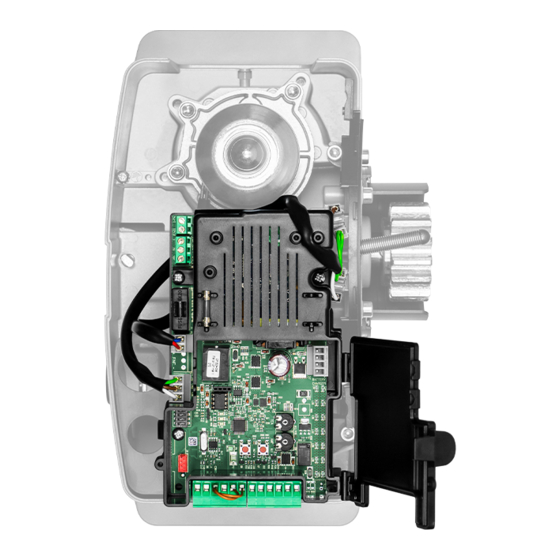
    STEUERGERÄT CP.B24-SW ELEKTRISCHE ANSCHLÜSSE Die folgende Tabelle beschreibt die elektrischen Anschlüsse, wie dargestellt in Abb. 1: Klemmen Funktion Beschreibung Wahl der Netzstromversor- 230 Vac 50/60 Hz (von 207 bis 253 Vac) Polbrücke M7 OFFEN SEL 115/230 gung 115 Vac 50/60 Hz (von 102 bis 125 Vac) Polbrücke M7 GESCHLOSSEN...
  • Seite 18 ÄNDERUNG DER BEREICHE DER VERLANGSAMUNG Während der AUTOSET-Phase kann ein größerer Bereich der Verlangsamung als der vom Steuergerät voreingestellte, eingerichtet werden. Wie folgt vorgehen: 1) Den Türflügel auf SCHLIESSUNG bringen (die Aktivierung des SWC-Endschalters prüfen) 2) Einen AUTOSET-Vorgang starten. Halten Sie die Tasten PU1+PU2 gedrückt, bis die 3 roten LEDs zyklisch aufleuchten. 3) Die Tür startet ein Öffnungsmanöver.
  • Seite 19 DIP 2 Der DIP 2 ermöglicht: - Auswahl der Betriebsart des Eingangs PHOTO - Auswahl der Betriebsart der „Taste P.P,“ und des Senders. (P.P.) - Aktivierung des STOPP-Eingangs als Fußgängereingang (teilweise Öffnung) (STOP/PED) Der Vorgang beinhaltet, dass DIP 2 auf ON gestellt wird, die beschriebenen Vorgänge ausgeführt werden und dann wieder auf OFF gestellt wird, um die Programmierung zu bestätigen.
  • Seite 20: Einstellung Der Geschwindigkeit Der Öffnungs- Und Schliessmanöver

    EINSTELLUNG DER GESCHWINDIGKEIT DER ÖFFNUNGS- UND SCHLIESSMANÖVER Die Geschwindigkeit der Öffnungs- und Schließmanöver kann mit diesem Vorgang eingestellt werden (die Verlangsamungsgeschwindigkeit bleibt ungeändert): Die DIP 1 und DIP 2 auf ON stellen. Mit der Taste PU1 wird die Geschwindigkeit der SCHLIESSUNG ausgewählt und durch die LED LD3 angezeigt: LD3 1 Blinksignal 50% der maximalen Geschwindigkeit (Standard) LD3 2 Blinksignale...
  • Seite 21: Gesamte Rücksetzung

    Löschen aller Sender aus dem Speicher - Halten Sie die PU2-Taste 15 Sekunden lang gedrückt, die LED LD1/2/3 und das Servicelicht beginnen schnell zu blinken und erlöschen, wenn der Löschvorgang abgeschlossen ist. - Lassen Sie die PU2-Taste los, der Speicher wurde gelöscht. HINWEIS: Aus Sicherheitsgründen ist es nicht möglich, Sender während der Öffnungs-/Schließphasen des Motors zu speichern.
  • Seite 22: Avertissements

    AVERTISSEMENTS INFORMATIONS GÉNÉRALES Il est interdit d’utiliser ce produit pour l’utilisation du produit ou avec des finalités ou modalités non prévues par le présent manuel. Toute autre utilisation pourrait compromettre l’intégrité du produit et présenter un danger pour les personnes ou pour les biens.
  • Seite 23: Branchements Électriques

    CENTRALE DE COMMANDE CP.B24-SW BRANCHEMENTS ÉLECTRIQUES Le tableau suivant décrit les branchements électriques représentés en Fig. 1: Bornes Fonction Description Sélection alimentation de 230 Vac 50/60 Hz (de 207 à 253 Vac) pontet M7 OUVERT SEL 115/230 réseau 115 Vac 50/60 Hz (de 102 à 125 Vac) pontet M7 FERMÉ...
  • Seite 24 MODIFICATION DES ESPACES DE RALENTISSEMENT Durant la phase d’AUTOSET, il est possible d’établir un espace de ralentissement supérieur à celui qui est configuré de défaut de la centrale. Procéder ainsi: Positionner le vantail en position de FERMETURE (vérifier l’activation de la butée SWC) Démarrer une procédure d’AUTOSET: presser et maintenir pressées les touches PU1+PU2 jusqu’à...
  • Seite 25 Activation/désactivation Apprentissage à distance des émetteurs (REM) Après avoir placé le DIP1 sur On en appuyant simultanément sur PU1+PU2, on active ou on désactive l’apprentissage à distance, décrit dans le paragraphe “Apprentissage à distance d’un émetteur”. Remarque : La réception des émetteurs dupliqués de la série “AK” est activée ou désactivée simultanément. Le LED LD3 signale l’état de la fonction: LED LD3 allumé: Apprentissage à...
  • Seite 26 portail ouvert ou en mouvement, l’intervention de la photocellule provoque la fermeture automatique (avec après 3s. Active uniquement avec TCA activé Le LED LD3 signale l’état de la fonction: LED LD3 allumé: Fermeture rapide activée. LED LD3 éteint: Fermeture rapide désactivée (défaut). ATTENTION: Au terme de la programmation, replacer le DIP 3 sur OFF.
  • Seite 27: Reset Total

    Apprentissage à distance d’un émetteur Si on dispose d’un émetteur déjà mémorisé, il est possible d’en mémoriser d’autres sans accéder à la centrale. La mémorisation à distance doit être effectuée avec le vantail en ouverture totale, indépendamment du réglage du TCA. Procéder ainsi: Appuyer sur la touche cachée de l’émetteur déjà...
  • Seite 28: Datos Técnicos

    ADVERTENCIAS INFORMACIÓN GENERAL Está prohibido utilizar el producto para finalidades o con modalidades no previstas en el presente manual. Usos incorrectos pueden causar daños al producto y poner en peligro personas y cosas. Se rehúsa cualquier responsabilidad en caso de incumplimiento de la buena técnica en la construcción de las cancelas, así como en cuanto a las deformaciones que pudieran producirse durante el uso.
  • Seite 29: Conexiones Eléctricas

    CENTRAL DE MANDO CP.B24-SW CONEXIONES ELÉCTRICAS En la siguiente tabla se describen las conexiones eléctricas representadas en la Fig. 1: Bornes Función Descripción Selección alimentación 230 Vca 50/60 Hz (de 207 a 253 Vca) puente M7 ABIERTO SEL 115/230 de red 115 VcA 50/60 Hz (de 102 a 125 Vca) puente M7 CERRADO Entrada para alimentación de red 115Vca/230Vca que puede seleccionarse median-...
  • Seite 30 MODIFICACIÓN DE LOS ESPACIOS DE RALENTIZACIÓN Durante la fase de AUTOCONFIGURACIÓN, se puede establecer un espacio de ralentización mayor al configurado por defecto por la central. Proceder de la siguiente manera: 1) Colocar la hoja en la posición de CIERRE (comprobar la activación del final de carrera SWC) 2) Iniciar el procedimiento de AUTOCONFIGURACIÓN: apretar y mantener apretados los botones PU1+PU2 hasta el encendido cíclico de los 3 LEDs rojos.
  • Seite 31 El LED LD3 indica el estado de la función: LED LD3 encendido: Aprendizaje a distancia activado (por defecto) LED LD3 apagado: Aprendizaje a distancia desactivado ATENCIÓN: Al final de la programación volver a poner el DIP 1 en OFF. DIP 2 El DIP 2 permite: - Seleccionar el modo de funcionamiento de la entrada PHOTO - Seleccionar el modo de funcionamiento del ”Botón P.P.”...
  • Seite 32 Activación/desactivación CIERRE RÁPIDO (SCL) Después de colocar el interruptor DIP3 en ON, pulsando al mismo tiempo PU1+ PU2 se activa o se desactiva el cierre rápido (con la cancela abierta o en movimiento, la intervención de la fotocélula provoca el cierre automático después de 3s. Activa solo con TCA habilitado) El LED LD3 indica el estado de la función: LED LD3 encendido:...
  • Seite 33: Diagnóstico Led

    Aprendizaje a distancia de un transmisor Si se dispone de un transmisor ya memorizado, es posible memorizar los demás sin tener que acceder a la central. La memorización a distancia debe realizarse con la puerta en apertura total, independientemente de la configuración del TCA. Proceder de la siguiente manera: 1 Apretar el botón oculto del transmisor ya memorizado.
  • Seite 34: Ostrzeżenia

    OSTRZEŻENIA INFORMACJE OGÓLNE Zabrania się używania produktu do celów i w sposób inny niż przewidziane w niniejszym podręczniku. Nieprawidłowe używanie może spowodować uszkodzenie produktu i stanowić zagrożenie dla osób i rzeczy. Nie bierze się na siebie żadnej odpowiedzialności za nieprzestrzeganie reguł dobrej techniki budowlanej przy realizacji bram, a także w przypadku odkształceń, które mogłyby powstać...
  • Seite 35: Podłączenia Elektryczne

    CENTRALKA STEROWNICZA CP.B24-SW PODŁĄCZENIA ELEKTRYCZNE W poniższej tabeli opisano podłączenia elektryczne przedstawione na Rys. 1: Zaciski Funkcja Opis Wybór zasilania siecio- 230 Vac 50/60 Hz (od 207 do 253 Vac) mostek M7 OTWARTY SEL 115/230 wego 115Vac 50/60 Hz (od 102 do 125 Vac) mostek M7 ZAMKNIĘTY...
  • Seite 36 niania, podając komendę P.P. (nadajnik, wejście P.P., przycisk PU1) w wybranym momencie. Następnie, rozpocznie się OTWIERANIE z normalną prędkością, w trakcie tego manewru, można wybrać punkt rozpoczęcia zwal- niania, podając komendę P.P. (nadajnik, wejście P.P., przycisk PU1) w wybranym momencie. Po zakończeniu procedury, drzwi zatrzymują...
  • Seite 37 DIP 2 DIP 2 umożliwia: - wybór trybu pracy wejścia PHOTO - wybór trybu działania „Przycisku P.P.” i nadajnika. (P.P.) - włączenie wejścia STOP jako wejścia pieszego (częściowe otwarcie) (STOP/PED) Procedura przewiduje ustawienie DIP 2 w pozycji ON; wykonać opisane czynności a następnie ustawić go w pozycji OFF w celu zatwierdzenia programowania.
  • Seite 38 DIP 4 Wyłącza funkcję oszczędzania energii ESA. Jeśli funkcja ESA jest aktywna, po zakończeniu otwierania lub zamykania, centralka ustawia się w warunkach maksymalnego oszczę- dzania energii, zmniejszając do minimum pobór energii i wyłączając wyjścia urządzeń pomocniczych. On: Funkcja oszczędzania energii ESA nieaktywna. Zastosować...
  • Seite 39 Nowy nadajnik jest zapisany, nadajnik odbierający wychodzi z fazy programowania. Przykład: na przycisku 1 TX „A” jest zapisana funkcja P.P., którą chce się przypisać do klawisza 2 nowego TX „B”; nacisnąć kolejno: ukryty klawisz TX A >> przycisk 1 TX A >> ukryty klawisz TX B >>przycisk 2 TX B. Usuwanie wszystkich nadajników z pamięci Przytrzymać...
  • Seite 40: Eg-Konformitätserklärung (Doc)

    36066 - Sandrigo (VI) - Italia +39 0444 751030 +39 0444 751030 Telefono: Telephone number: sales@beninca.it sales@beninca.it E-mail: E-mail address: Dichiara che il documento è rilasciato sotto la propria responsabilità e appartiene al seguente prodotto: Declare that the DOC is issued under our sole responsibility and belongs to the following product:...
  • Seite 41 Kod pocztowy i miasto: Teléfono: +39 0444 751030 Telefon: +39 0444 751030 sales@beninca.it sales@beninca.it E-mail: Adres e-mail: Declara que el documento ha sido emitido bajo la propia responsabilidad y pertenece al siguiente producto: Oświadcza, że dokument został wydany na własną odpowiedzialność i dotyczy produktu:...
  • Seite 42 AUTOMATISMI BENINCÀ SpA - Via Capitello, 45 - 36066 Sandrigo (VI) - Tel. 0444 751030 r.a. - Fax 0444 759728...

Inhaltsverzeichnis