Werbung
Verfügbare Sprachen
Verfügbare Sprachen
Inhaltsverzeichnis
All manuals and user guides at all-guides.com
PROFESSIONAL BATTERY BOOSTERS
OWNER'S MANUAL
Booster 12V
Booster 12/24V
Translation of the original operating instructions
EN...............................................................Page 3
DE.............................................................Page 13
1
Werbung
Inhaltsverzeichnis
Fehlerbehebung

Verwandte Anleitungen für Herth+Buss Reanimator 4600


Inhaltszusammenfassung für Herth+Buss Reanimator 4600
- Seite 13 All manuals and user guides at all-guides.com DIESES BENUTZERHANDBUCH SPEICHERN UND VOR JEDEM BETRIEB LESEN. In diesem Handbuch wird erklärt, wie man das Aggregat sicher und effektiv nutzt. Bitte diese Anweisungen und Vorsichtsmaßnahmen gründlich lesen. WICHTIG: DIESES SICHERHEIT- UND BEDIENUNGSHANDBUCH LESEN UND SPEICHERN DIESE ANWEISUNGEN SPEICHERN –...
-
Seite 14: Wichtige Sicherheitsanweisungen - Diese Anweisungen Speichern
All manuals and user guides at all-guides.com 1. WICHTIGE SICHERHEITSANWEISUNGEN – DIESE ANWEISUNGEN SPEICHERN Dieses Handbuch enthält wichtige Sicherheits- und Betriebsanweisungen. GEFAHR EINES STROMSCHLAGS ODER BRANDES. WARNUNG 1.1. Vor der Nutzung dieses Produkts das gesamte Handbuch durchlesen. Geschieht dies nicht, so könnte dies zur schweren Verletzungen oder zum Tod führen. -
Seite 15: Persönliche Vorsichtsmassnahmen
All manuals and user guides at all-guides.com 2. PERSÖNLICHE VORSICHTSMASSNAHMEN GEFAHR EXPLOSIVER GASE. EIN FUNKEN IN DER NÄHE DER WARNUNG BATTERIE KANN ZU EINER BATTERIEEXPLOSION FÜHREN. ZUR VERMINDERUNG DER GEFAHR EINES FUNKENFLUGS IN BATTERIENÄHE: 2.1. NIEMALS in der Umgebung der Batterie oder des Verbrennungsmotors rauchen oder Funken- oder Brandquelle aufstellen. - Seite 16 All manuals and user guides at all-guides.com 4. DIESE SCHRITTE FÜR DAS HERSTELLEN EINES BATTERIEANSCHLUSSES BEFOLGEN WARNUNG EIN FUNKEN IN DER NÄHE DER BATTERIE KANN ZU EINER BATTERIEEXPLOSION FÜHREN. ZUR VERMINDERUNG DER GEFAHR EINES FUNKENFLUGS IN BATTERIENÄHE: 4.1. Die Ausgangskabel, wie unten beschrieben, an die Batterie und an das Chassis anschließen. Die Ausgangsklemmen dürfen nie einander berühren.
-
Seite 17: Aufladen Der Internen Batterie Des Boosters
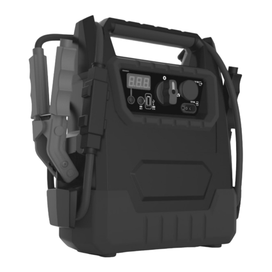
All manuals and user guides at all-guides.com 1. Massive Batterieklemmen 2. Display-Knopf 3. Digitales Display 4. USB-Knopf 5. USB-Anschluss 6. Booster EIN/AUS-Schalter – 0 bzw. 12V Stellung bei Modell 12V / 0 bzw. 12V bzw. 24V Stellung bei Modell 12/24V 7. - Seite 18 All manuals and user guides at all-guides.com 6.1.2 LED-Anzeigen am Ladegerät (Grüne) STROMVERSORGUNGS-LED an: Das Ladegerät ist an der Wechselstromquelle angeschlossen. (Gelbe/orange) LADE-LED blinkt langsam: Das Ladegerät lädt die Batterie im Booster oder ist im Haltemodus. (Gelbe/orange) LADE-LED blinkt schnell: Das Ladegerät hat ein Problem an der Batterie festgestellt.
- Seite 19 All manuals and user guides at all-guides.com Das Ladegerät an der Wand-Steckdose anschließen und sicherstellen, dass die grüne STROMVERSORGUNGS-LED am Ladegerät aufleuchtet. Prüfen, ob die gelbe LADE-LED am Ladegerät langsam zu blinken beginnt und damit anzeigt, dass der Ladevorgang begonnen hat. Um den Ladestatus zu erfahren, die auf dem Booster- Display angezeigte Prozentzahl überprüfen.
-
Seite 20: Austausch Der Sicherung Am Booster
All manuals and user guides at all-guides.com 7.4 Stromversorgung eines USB-Geräts Der Booster ist eine Stromquelle für alle Zubehörteile mit USB-Stecker. Der USB-Anschluss liefert bis zu 2,1A bei 5V Gleichstrom. 6. Sicherstellen, dass die Batterieklemmen gut an den Klemmenhaltern befestigt sind. 7. -
Seite 21: Wartungsanweisungen
All manuals and user guides at all-guides.com 9. WARTUNGSANWEISUNGEN 9.1. Reinigungs- und Benutzer-Wartungsarbeiten sollten nicht von unbeaufsichtigten Kindern durchgeführt werden. 9.2. Vor jeglichen Wartungs- oder Reinigungsarbeiten zunächst das Ladegerät vom Booster abklemmen. 9.3. Mit einem trockenen Tuch jegliche Batteriekorrosion oder anderen Schmutz oder Öl von den Batterieklemmen, den Kabeln und vom Boostergehäuse abwischen. - Seite 22 All manuals and user guides at all-guides.com Wenn das Ladegerät Keine Spannung an der Prüfen, ob Sicherung an der korrekt angeschlossen Wechselstromdose. Wechselstromdose oder Schutzschalter ist, leuchtet die grüne ausgelöst ist. STROMVERSORGUNGS- Mangelhafter elektrischer Prüfen, ob die Stecker am Netz- LED nicht.