RICOO FS0444 Montageanleitung
Fahrbarer tv und dvd stand
Verfügbare Sprachen
Verfügbare Sprachen
Quicklinks
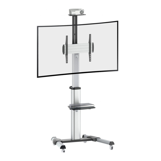
Fahrbarer TV und DVD Stand
!
Diese Wandhalterung unterstützt
folgende Lochabstände:
Horizontal / Waagerecht
Vertikal / Senkrecht
FS0444
FS0464
All manuals and user guides at all-guides.com
Bitte überprüfen Sie VOR der Montage den Lochabstand zwischen den
VESA - Befestigungslöchern an Ihrem Bildschirm
Horizontal / Waagerecht
200x200
300x300
400x200
400x400
600x400
VESA-Befestigungslöcher
Vertikal /
Senkrecht
Bildschirm Rückseite
FS0444
min. 200mm
max. 400mm
min. 200mm
max. 408mm
TV
DVD
50kg
5kg
(110lbs)
(11lbs)
MAX
MAX
MONTAGEANLEITUNG
ACHTUNG: NIEMALS DAS MAXIMAL
ZULÄSSIGE BELASTUNGSGEWICHT
ÜBERSCHREITEN. MISSACHTUNG
KANN ZU SACHSCHÄDEN ODER
SCHWEREN VERLETZUNGEN FÜHREN!
FS0464
max.600mm
max. 408mm
Kamera
5kg
(11lbs)
MAX
Deutsch
English
v.17.03

Verwandte Anleitungen für RICOO FS0444


Inhaltszusammenfassung für RICOO FS0444
- Seite 1 Bitte überprüfen Sie VOR der Montage den Lochabstand zwischen den VESA - Befestigungslöchern an Ihrem Bildschirm VESA-Befestigungslöcher Vertikal / Senkrecht Horizontal / Waagerecht Bildschirm Rückseite Diese Wandhalterung unterstützt folgende Lochabstände: FS0444 FS0464 Horizontal / Waagerecht min. 200mm max. 400mm max.600mm Vertikal / Senkrecht min. 200mm max. 408mm max.
- Seite 2 All manuals and user guides at all-guides.com ACHTUNG: Lesen Sie die gesamte Bedienungsanleitung durch, bevor Sie mit der Montage beginnen. WARNUNG • Beginnen Sie nicht mit der Montage, bis Sie alle Anweisungen und Warnungen, welche in dieser Montageanleitung vorhanden sind, durchgelesen und verstanden haben. Wenn Sie Fragen zu den Anweisungen oder Warnungen haben, kontaktieren Sie bitte Ihren Händler.
-
Seite 3: Lieferumfang
All manuals and user guides at all-guides.com Lieferumfang WICHTIG: Stellen Sie vor der Montage sicher, dass alle Teile welche hier aufgeführt sind, bei der Lieferung dabei sind. Sollten Teile fehlen oder defekt sein, kontaktieren Sie Ihren Händler. A (x1) D (x1) E (x1) B (x1) C (x1) - Seite 4 All manuals and user guides at all-guides.com Schritt • Standfüße an der Bodenplatte mit Hilfe der "Q"-Schrauben montieren. • Feinjustierung: Rollfüße durch das Lockern / Zuziehen der Fixiermutter in der Höhe einstellen. Schritt 2 ACHTUNG: Bitte beim lassen der Schrauben, die innere Säule fest- halten.
- Seite 5 All manuals and user guides at all-guides.com Die Säule an der Bodenplatte mit Schrauben "W" fixieren. Alle Schrauben festziehen. Deutsch English...
- Seite 6 All manuals and user guides at all-guides.com Schritt Aufnahmeplatte auf der Säule mit "U"-Schrauben fixieren. Alle Schrauben mit passendem Schraubenzieher festziehen. Schritt Metallscheiben "P" in die Führungen in der Frontplatte "G" einführen. Montageschienen "I" auf die Frontplatte aufsetzen. Löcher der Montage- schienen mit den Metallscheiben "P"...
- Seite 7 All manuals and user guides at all-guides.com Frontplatte inkl. Montageschienen am Bildschirm anlegen und die Montageschienen auf die VESA-Löcher auf der Bildschirm- Rückseite ausrichten. Schrauben an den Montageschienen fest anziehen. BEACHTEN: Stellen Sie sicher, dass Löcher der Montageschienen mit den VESA-Löchern übereinstimmen. Deutsch English...
- Seite 8 All manuals and user guides at all-guides.com Schritt 4-1 M-A/M-B/M-C Schritt 4-2 (für Bildschirme mit gewölbter Rückseite) oder oder oder oder oder Beachten: Wählen Sie die zu Ihrem TV passenden Schrauben, Unterlegscheiben und falls erforderlich die Abstandshalter. · Fixieren Sie die Montageschienen mit Hilfe von den dazugehörigen Schrauben. Ziehen Sie alle Schrauben nach.
- Seite 9 All manuals and user guides at all-guides.com Schritt 5 · Bildschrim inkl. Frontplatte auf die Aufnahmeplatte an der Säule aufhängen. · Mit zwei Schrauben "X" fixieren und alle Schrauben festziehen. WICHTIG: Bevor Sie das Bildschirm loslassen, stellen Sie bitte sicher, dass der Bildschirm korrekt montiert ist und alle Schrauben fest angezogen sind Schritt 6 Plastikhalter...
- Seite 10 All manuals and user guides at all-guides.com Schritt 7 Schritt 8 (optional) Die Kamera-Halterung auf die Montage- platte mit Hilfe der Schrauben "S" und "T" montieren. Alle Schrauben mit passendem Schraubenzieher festziehen. Deutsch English...
- Seite 11 All manuals and user guides at all-guides.com Schritt 9 ( optional) Montageplatte in der gewünschten Höhe auf der Säule mit den Schrauben "R" fixieren. Alle Schrauben mit passendem Schrauben- zieher festziehen. Schritt 10 oder A: Für Landschaftsmodus B: Für Portraitmodus Frontplatte mit zwei Schrauben Zwei Schrauben entfernen, den Bildschirm um 90°...
- Seite 12 All manuals and user guides at all-guides.com Schritt 11. Fertig Lockern Sie die gezeigten Plastikknobs und stellen Sie die gewünschte +5°/-12° Bildschirm-Neigung ein. Danach ziehen Sie Knobs wieder zu um die Fertig Neigungseinstellung zu fixieren. 1200mm 1250mm 1300mm 1350mm 1400mm 1450mm 1500mm Abstand von der Front-...