
Verwandte Anleitungen für Stahl ispac 9160 Rev F


Inhaltszusammenfassung für Stahl ispac 9160 Rev F
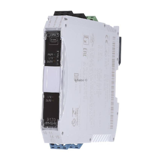
- Seite 1 Typ/Type 9160 Rev F Messumformerspeisegerät Transmitter Supply Unit Betriebsanleitung (vorläufig) Operating Instructions (preliminary)
-
Seite 2: Inhaltsverzeichnis
Operating Instructions english Inhaltsverzeichnis Allgemeine Angaben ....................3 Hersteller ......................3 Angaben zu Betriebsanleitung ................3 Verwendete Symbole ....................3 Sicherheitshinweise ....................3 Normenkonformität...................... 4 Funktion ........................4 Kennzeichnung und technische Daten ................ 5 Geräteaufbau ......................6 Projektierung ....................... 6 Maximal zulässige Umgebungstemperaturen ............ -
Seite 3: Allgemeine Angaben
Kenntnis der geltenden Vorschriften und Bestimmungen. Bei Errichtung und Betrieb ist Folgendes zu beachten: Bei SIL Anwendungen FMEDA Report SIL STAHL 05/08-34 R008 und das Sicherheitshandbuch beachten. Das Gerät ist in Zone 2, Zone 22 oder außerhalb explosionsgefährdeter Bereiche zu installieren. -
Seite 4: Normenkonformität
Das Gerät darf nur in unbeschädigtem, trockenem und sauberem Zustand eingebaut und betrieben werden. Sollten Sie Fragen bezüglich der richtigen Handhabung des Gerätes haben, wenden Sie sich bitte an R. STAHL Schaltgeräte GmbH, Am Bahnhof 30, 74638 Waldenburg, Germany, Telefon +49-7942-943-0 wenden oder an eine unserer Niederlassungen, siehe www.stahl-ex.com. -
Seite 5: Kennzeichnung Und Technische Daten
Operating Instructions 6 Kennzeichnung und technische Daten Hersteller R. STAHL Typbezeichnung 9160/**-1*-1* CE-Kennzeichnung 0158 ATEX Kennzeichnung Explosionsschutz II 3 (1)G Ex nA nC [ia Ga] IIC T4 Gc II (1) D [Ex ia Da] IIIC Prüfstelle und Bescheinigungsnummer DMT 03 ATEX E 010 X... -
Seite 6: Geräteaufbau
Es erlischt die Herstellerhaftung und Gewährleistung. Der Schaltschrank muss in einer Art aufgebaut sein, der es erlaubt das Gerät im spezifizierten Temperaturbereich zu betreiben. Das Dokument ist verfügbar unter: www.stahl-ex.com. 9 Anordnung und Montage 9.1 Maßzeichnung Maß X Schraubklemmen... -
Seite 7: Installation
Bei Betrieb in Zone 2, 22 ist das Gerät in ein Gehäuse einzubauen, das den Anforderungen der EN 60079-15 genügt (z.B. in ein Gehäuse Typ 8146 der Firma R. STAHL Schaltgeräte GmbH). Montage und Demontage 9.3.1. Montage / Demontage pac-Bus Der pac-Bus ist ein Zubehör, dass die Verdrahtung der Hilfsenergie und das... -
Seite 8: Montage / Demontage Auf Pac-Träger
Operating Instructions english Demontage Fußriegel (1) mit dem Schraubendreher etwas herausziehen. Gerät herausschwenken. 9.3.3. Montage / Demontage auf pac-Träger Montage Schwarze und grüne Klemmen entfernen. Bei einkanaligen Geräten: Abdeckung im Klemmenschacht 2 entfernen (zwischen schwarzer und grüner Klemme) ... -
Seite 9: Inbetriebnahme
english Operating Instructions 9.3.4. Montage / Demontage abziehbare Klemmen Alle Geräte sind mit abziehbaren Klemmen ausgestattet. Demontage Schraubendreher hinter Klemme ansetzen. Klemme herausdrücken. Montage Klemme in Gerät stecken, bis Klemme einrastet. 10 Inbetriebnahme 10.1 Anschlüsse LF )* LF )* Typen 9160/**-1*-1* mit HART... -
Seite 10: Einstellungen
Operating Instructions english Anschluss der Speisung (grüne Klemme 9-/7+): Art der Versorgung Anschluss Grüne Klemme mit den PIN’s 9- und 7+ Direkte Versorgung des Gerätes Versorgung über pac-Bus Siehe Kapitel 10 Eingangsbeschaltung (blaue Klemmen mit den PINs 10,11,12 und 13,14,15): Zwei-Leiter- Drei-Leiter- mA-Quelle... -
Seite 11: Betrieb- Und Betriebszustände
Gerät nicht beschädigt ist die Kabel ordnungsgemäß angeschlossen sind Bei detektierten Leitungsfehler ist Ausgangssignal gleich dem Eingangssignal. 12 Reparatur und Instandhaltung Reparaturen an den Geräten dürfen ausschließlich durch R. STAHL ausgeführt werden. Die Geräte sind wartungsfrei. Fehlersuchplan: Fehlererkennung Fehlerursache Fehlerbehebung LED „PWR“... -
Seite 12: General Information
When installing and operating the device, the following are to be observed: For SIL applications please observe the FMEDA report “SIL STAHL 05/08-34 R008” and the safety manual. The apparatus may be installed in Zone 2, Zone 22 or outside the explosion hazard areas. -
Seite 13: Conformity To Standards
Should there be any question about the correct handling of the module, please contact R. STAHL Schaltgeräte GmbH, Am Bahnhof 30, 74638 Waldenburg, Germany, telephone +49-7942-943-0, or contact one of our offices or representatives see www.stahl-ex.com. 4 Conformity to standards The information about the conformity to standards can be found in the manufacturer’s... -
Seite 14: Marking And Technical Data
Operating Instructions english 6 Marking and technical data Manufacturer R. STAHL Type designation 9160/**-1*-1* CE marking 0158 ATEX explosion protection marking II 3 (1)G Ex nA nC [ia Ga] IIC T4 Gc II (1) D [Ex ia Da] IIIC Testing authority and certificate number... -
Seite 15: Device Description
The manufacturer’s liability and warranty expire. The cabinet need to be built in a way which allows to operate the device within the specified temperature range The cabinet installation guide is available on www.stahl-ex.com. 9 Arrangement and fitting 9.1 Dimension drawing... -
Seite 16: Installation
In the case of operation in Zone 2 or Zone 22, the transmitter supply unit must be fitted in an enclosure which complies with the requirements of EN 60079-15 (e.g. in an enclosure type 8146 from the R. STAHL). 9.3 Mounting and dismounting 9.3.1. - Seite 17 english Operating Instructions Dismounting Pull the latch (1) with the screw driver out. Swivel the device out. 9.3.3. Mounting / Dismounting on pac-Carrier Mounting Dismount the black and the green terminal. (see chapter 8.3.3) Single channel device: Dismount the cover of terminal slot 2. (between black and green terminal) ...
-
Seite 18: Commissioning
Operating Instructions english 9.3.4. Mounting / Dismounting detachable terminals All devices are equipped with detachable terminals. Dismounting Place the screw driver between terminal and enclosure. Move the screw driver as described. Mounting Place the terminal into the terminal slot and press it towards the device until it is locked. 10 Commissioning 10.1 Connections Hazardous area... -
Seite 19: Settings
english Operating Instructions Connection of power supply (green terminal pin 9- / 7+): Type of power supply Connection Direct supply of device Green terminal PIN 9- and 7+ Power supply via pac-Bus See chapter 10. Input connections (blue terminals PIN 10,11,12 and 13,14,15): Two-wire- Three-wire- mA-source... -
Seite 20: Operation And Operational States
If device fuse is defective, send device in for repair. If the procedure described above does not obtain the desired result, please contact your local R.STAHL sales and service representative. In order to quickly process your request, please provide us with the following information: ... -
Seite 21: Ec-Type Examination Certificate
EC-Type Examination Certificate... - Seite 24 R. STAHL Schaltgeräte GmbH Am Bahnhof 30 74638 Waldenburg (Württ.) – Germany www.stahl.de SAP: 221787 ID-Nr. 9160617310 S-BA-9160-000 Ex-de/en-/2013...