MSI X399 SLI PLUS Kurzanleitung
Inhaltsverzeichnis
Verfügbare Sprachen
Verfügbare Sprachen
Quicklinks
Quick Start
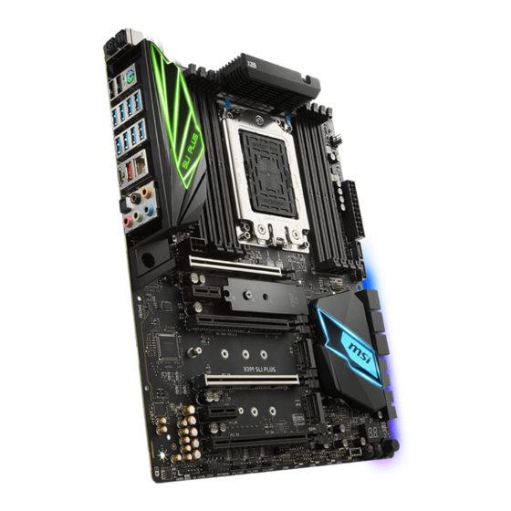
X399 SLI PLUS
Thank you for purchasing the MSI
motherboard.
®
This Quick Start section provides demonstration diagrams about
how to install your computer. Some of the installations also provide
video demonstrations. Please link to the URL to watch it with the web
browser on your phone or tablet. You may have even link to the URL
by scanning the QR code.
Kurzanleitung
X399 SLI PLUS
Danke, dass Sie das MSI
Motherboard gewählt
®
haben. Dieser Abschnitt der Kurzanleitung bietet eine Demo zur
Installation Ihres Computers. Manche Installationen bieten auch
die Videodemonstrationen. Klicken Sie auf die URL, um diese
Videoanleitung mit Ihrem Browser auf Ihrem Handy oder Table
anzusehen. Oder scannen Sie auch den QR Code mit Ihrem Handy,
um die URL zu öffnen.
Présentation rapide
X399 SLI
PLUS. Ce manuel
Merci d' avoir choisi la carte mère MSI
®
fournit une rapide présentation avec des illustrations explicatives
qui vous aideront à assembler votre ordinateur. Des tutoriels vidéo
sont disponibles pour certaines étapes. Cliquez sur le lien fourni
pour regarder la vidéo sur votre téléphone ou votre tablette. Vous
pouvez également accéder au lien en scannant le QR code qui lui est
associé.
Быстрый старт
Благодарим вас за покупку материнской платы MSI
X399
®
PLUS. В этом разделе представлена информация,
SLI
которая поможет вам при сборке комьютера. Для некоторых
этапов сборки имеются видеоинструкции. Для просмотра
видео, необходимо открыть соответствующую ссылку в
веб-браузере на вашем телефоне или планшете. Вы также
можете выполнить переход по ссылке, путем сканирования
QR-кода.
I
Quick Start
Kapitel
Inhaltsverzeichnis

Verwandte Anleitungen für MSI X399 SLI PLUS


Inhaltszusammenfassung für MSI X399 SLI PLUS
- Seite 1 URL zu öffnen. Présentation rapide X399 SLI PLUS. Ce manuel Merci d’ avoir choisi la carte mère MSI ® fournit une rapide présentation avec des illustrations explicatives qui vous aideront à assembler votre ordinateur. Des tutoriels vidéo sont disponibles pour certaines étapes. Cliquez sur le lien fourni pour regarder la vidéo sur votre téléphone ou votre tablette.
- Seite 2 Installing a Processor/ Installation des Prozessors/ Installer un processeur/ Установка процессора https://youtu.be/yk4EpVUU03E Quick Start...
-
Seite 10: Power On/ Einschalten/ Mettre Sous-Tension/ Включение Питания
Power On/ Einschalten/ Mettre sous-tension/ Включение питания Quick Start... - Seite 57 Inhalt Sicherheitshinweis ....................3 Spezifikationen ...................... 4 Rückseite E/A ......................9 LAN Port LED Zustandstabelle ................9 Konfiguration der Audioanschlüsse ............... 9 Realtek HD Audio Manager .................. 10 Übersicht der Komponenten ................12 CPU Sockel ......................13 OC1: GAME BOOST Drehschalter ................ 16 JSLOW1: Slow Mode Booting Steckbrücke ............
- Seite 58 BIOS-Setup ......................36 Öffnen des BIOS Setups..................36 Reset des BIOS ..................... 37 Aktualisierung des BIOS ..................37 EZ Modus ......................39 Erweiterter Modus ....................41 OC Menü........................ 42 Softwarebeschreibung ..................47 Installation von Windows 10 ................47 ® Installation von Treibern ..................47 Installation von Utilities ..................
-
Seite 59: Sicherheitshinweis
Sicherheitshinweis y Die im Paket enthaltene Komponenten sind der Beschädigung durch elektrostatischen Entladung (ESD). Beachten Sie bitte die folgenden Hinweise, um die erfolgreichen Computermontage sicherzustellen. y Stellen Sie sicher, dass alle Komponenten fest angeschlossen sind. Lockere Steckverbindungen können Probleme verursachen, zum Beispiel: Der Computer erkennt eine Komponente nicht oder startet nicht. -
Seite 60: Spezifikationen
Unterstützt DDR4 3600+(OC)/ 3466(OC)/ 3333(OC)/ 3200(OC)/ 3066(OC)/ 2933(OC)/ 2800(OC)/ 2667(OC)/ 2400/ Speicher 2133 MHz* * Weitere Informationen zu kompatiblen Speicher finden Sie unter: http://www.msi.com ** Nähere Informationen hierzu finden Sie im Abschnitt der DIMM- Steckplätze. y 4x PCIe 3.0 x16-Steckplätze Erweiterung- anschlüsse... - Seite 61 Fortsetzung der vorherigen Seite y ASMedia ASM3142 Chipsatz ® ƒ 1x USB 3.1 Gen2 (SuperSpeed USB 10Gbps) Typ-C Anschluss an der rückseitigen Anschlussleiste ƒ 1x USB 3.1 Gen2 (SuperSpeed USB 10Gbps) Typ-A Anschluss an der rückseitigen Anschlussleiste y AMD X399 Chipsatz ®...
- Seite 62 Fortsetzung der vorherigen Seite y 1x 24-poliger ATX Stromanschluss y 2x 8-polige ATX Stromanschlüsse y 1x 6-poliger ATX 12V Stromanschluss* y 8x SATA 6Gb/s Anschlüsse y 2x USB 2.0 Anschlüsse (unterstützt zusätzliche 4 USB 2.0-Ports) y 2x USB 3.1 Gen1 Anschlüsse (unterstützt zusätzliche 4 USB 3.1 Gen1-Ports) y 1x USB 3.1 Gen2 Typ-C Anschluss Interne Anschlüsse...
- Seite 63 LIVE UPDATE 6 y SMART TOOL Software y X-BOOST y MYSTIC LIGHT y RAMDISK y NETWORK MANAGER y CPU-Z MSI GAMING y Norton Internet Security Solution ™ y Google Chrome , Google Toolbar, Google Drive ™ Fortsetzung auf der nächsten Seite...
-
Seite 64: Besondere Funktionen
Fortsetzung der vorherigen Seite y Audio Boost 4 y Triple Turbo M.2 y Pumpe-Lüfter y Smart-Lüftersteuerung y Mystic Light y Mystic Light Extension y Mystic Light SYNC y EZ DEBUG LED y M.2-Abdeckung y PCI-E Steel Armor y Multi GPU – SLI Technologie y Multi GPU –... -
Seite 65: Rückseite E/A
Rückseite E/A Audioanschlüsse VR READY Anschlüsse Flash BIOS Anschluss PS/2 Clear CMOS Taste Optischer S/PDIF-Ausgang USB 2.0 Flash BIOS Taste USB 3.1 Gen2 Typ-C USB 3.1 Gen1 USB 3.1 Gen2 Typ-A y Clear CMOS Taste - Schalten Sie den Computer aus. Halten Sie die Taste „Clear CMOS “... -
Seite 66: Realtek Hd Audio Manager
Realtek HD Audio Manager Nach der Installation des Realtek HD Audio-Treibers, wird das Symbol Realtek HD Audio Manager in der Taskleiste angezeigt. Klicken Sie doppelt auf dieses Symbol, um das Programm zu starten. Geräteauswahl Erweiterte Einstellungen Verbindungs- status Optimierungen Lautstärke Anschlüsse Profil y Geräteauswahl - Ermöglicht die Auswahl der Audio-Ausgangs Quelle. -
Seite 67: Audiobuchsen Für Den Anschluss Von Einem Kopfhörer Und Mikrofon
Audiobuchsen für den Anschluss von einem Kopfhörer und Mikrofon Audiobuchsen für Stereo-Lautsprecher AUDIO INPUT Audiobuchsen für 7,1 Kanal Anlage AUDIO INPUT Rear Front Side Center/ Subwoofer Rückseite E/A... -
Seite 68: Übersicht Der Komponenten
Übersicht der Komponenten CPU_FAN1 CPU Sockel CPU_PWR1 CPU_PWR2 PUMP_FAN1 DIMMB2 DIMMC1 DIMMB1 DIMMC2 DIMMA2 DIMMD1 DIMMA1 DIMMD2 ATX_PWR1 SYS_FAN1 SATA1 PCIE_PWR1 JBAT1 SATA2 PCI_E1 M2_1 SATA▼3▲4 PCI_E2 SATA▼5▲6 PCI_E3 SATA▼7▲8 M2_2 JUSB5 PCI_E4 M2_3 JUSB4 PCI_E5 JFP2 PCI_E6 JSLOW JAUD1 JRGB1 JRAINBOW1 POWER1... -
Seite 69: Cpu Sockel
CPU Sockel Verwenden Sie den mit der AMD CPU mitgeliefert Torx-Schraubendreher und folgen Sie den Schritten unten, um die CPU zu installieren. Video-Demonstration Eine anschauliche Darstellung zum Einbau der AMD Ryzen Threadripper CPU finden Sie im Video. https://youtu.be/yk4EpVUU03E 1. Lösen Sie die Schrauben der Halterung mit dem AMD Torx-Schraubendreher in der gezeigten Reihenfolge 3→2→1. - Seite 70 3. Entfernen Sie die Pin-Schutzkappe und verschließen Sie den Rahmen ordnungsgemäß. PIN-Schutzkappe 4. Schließen Sie die Halterung und drehen Sie die Schrauben im Uhrzeigersinn mit dem Torx-Schraubendreher in der Reihenfolge 1→2→3→1→2→3, bis sie fest sitzen. AMD Torx- Schraubendreher 5. Ziehen Sie die Schrauben der Halterung fest, bis ein Klicken des Torx- Schraubendrehers zu hören ist.
- Seite 71 Sie jedoch bitte sicher, dass die betroffenen Komponenten mit den abweichenden Einstellungen während des Übertaktens zurecht kommen. Von jedem Versuch des Betriebes außerhalb der Produktspezifikationen kann nur abgeraten werden. MSI übernehmt keinerlei Garantie für die Schäden und Risiken, die aus einem unzulässigem Betrieb oder einem Betrieb außerhalb der Produktspezifikation resultieren.
-
Seite 72: Oc1: Game Boost Drehschalter
3. Drehen Sie den GAME BOOST Drehschalter auf 0 und schalten Sie den PC ein. Die Konfigurationsparameter werden auf die Normalwerte zurückgesetzt. Wichtig Sie können auch die GAME-Boost-Funktion im BIOS-Setup oder mit der MSI COMMAND CENTER-Software steuern. Übersicht der Komponenten... -
Seite 73: Jslow1: Slow Mode Booting Steckbrücke
System zu verbessern. Der Erfolg der Übertaktung hängt von den Komponenten des Computers ab. MSI gibt keine Garantie auf den GAME BOOST Übertaktungsbereich und auf eventuelle Schäden, die durch eine Übertaktung entstehen können. MSI-Komponenten werden für eine bessere GAME BOOST Kompatibilität empfohlen. -
Seite 74: Dimm-Steckplätze
DIMM-Steckplätze D2D1C2C1 A1A2B1B2 Speichermodul-Installationsempfehlung CPU Sockel 1 DIMM 2 DIMMs Sockel TR4 CPU 4 DIMMs 8 DIMMs DIMMB2 DIMMD2 DIMMB2 Übersicht der Komponenten... - Seite 75 DIMMC2 DIMMB2 DIMMB2 DIMMC1 DIMMD2 DIMMA2 DIMMB1 DIMMC2 DIMMD1 DIMMA2 DIMMA1 DIMMD2 Wichtig Um einen sicheren Systemstart zu gewährleisten, bestücken Sie immer DIMMB2 zuerst. Stellen Sie im Dual-/ Triple-/ Quad-Kanal-Modus bitte sicher, dass Sie Module des gleichen Typs und identischer Speicherdichte in den DIMM Slots unterschiedlicher Kanäle verwenden.
-
Seite 76: Pci_E1~6: Pcie Erweiterungssteckplätze
PCI_E1~6: PCIe Erweiterungssteckplätze PCI_E1: PCIe 3.0 x16 PCI_E2: PCIe 2.0 x1 PCI_E3: PCIe 3.0 x8 PCI_E4: PCIe 3.0 x16 PCI_E5: PCIe 2.0 x1 PCI_E6: PCIe 3.0 x8 Mehrere Grafikkarten Einbauempfehlung PCI_E1* PCI_E1* PCI_E4 PCI_E1* PCI_E1* PCI_E3 PCI_E3 PCI_E4 PCI_E4 PCI_E6 * Vorgehensweise zur Verhinderung eines leeren Bildschirminhalts während des POST-Vorgangs. - Seite 77 Wichtig Wenn Sie eine große und schwere Grafikkarte einbauen, benötigen Sie einen Grafikkarten-Stabilisator (Graphics Card Bolster) der das Gewicht trägt und eine Verformung des Steckplatzes vermeidet. Für die Installation einer einzelnen PCIe x16 Erweiterungskarte mit optimaler Leistung, empfehlen wir den PCI_E1 Steckplatz zu verwenden. Achten Sie darauf, dass Sie den Strom abschalten und das Netzkabel aus der Steckdose herausziehen, bevor Sie eine Erweiterungskarte installieren oder entfernen.
-
Seite 78: M2_1~3: M.2 Steckplätze (Key M)
M2_1~3: M.2 Steckplätze (Key M) Video-Demonstration In diesem Video erfahren Sie, wie Sie die M.2-Abdeckung verwenden. https://youtu.be/NwtQBpkUazs Installation eines M.2 Moduls 1. Entfernen Sie die Schraube aus dem 5. Setzen Sie die Schraube in die Schraubsockel. Aussparung an der Hinterkante des M2-Modul und schrauben 2. -
Seite 79: Sata1~8: Sata 6Gb/S Anschlüsse
SATA1~8: SATA 6Gb/s Anschlüsse Dieser Anschluss basiert auf der Hochgeschwindigkeitsschnittstelle SATA 6Gb/s. Pro Anschluss kann ein SATA Gerät angeschlossen werden. SATA1 SATA2 SATA4 SATA3 SATA6 SATA5 SATA8 SATA7 Wichtig Knicken Sie das SATA-Kabel nicht in einem 90° Winkel. Datenverlust könnte die Folge sein. -
Seite 80: Cpu_Pwr1~2, Atx_Pwr1, Pcie_Pwr1: Stromanschlüsse
CPU_PWR1~2, ATX_PWR1, PCIE_PWR1: Stromanschlüsse Mit diesen Anschlüssen verbinden Sie die ATX Stromstecker. CPU_PWR1/ CPU_PWR2 Ground +12V Ground +12V Ground +12V Ground +12V +3.3V +3.3V +3.3V -12V Ground Ground PS-ON# Ground Ground Ground ATX_PWR1 Ground Ground PWR OK 5VSB +12V +12V +3.3V Ground +12V... -
Seite 81: Jusb1~2: Usb 2.0 Anschlüsse
Bitte beachten Sie, dass Sie die mit VCC (Stromführende Leitung) und Ground (Erdleitung) bezeichneten Pins korrekt verbinden müssen, ansonsten kann es zu Schäden kommen. Um ein iPad, iPhone und einen iPod über USB-Anschlüsse aufzuladen, installieren Sie bitte die MSI SUPER CHARGER Software. ® JUSB4~5: USB 3.1 Gen1 Anschlüsse Mit diesen Anschlüssen können Sie die USB 3.1 Gen1 Anschlüsse auf dem Frontpanel... -
Seite 82: Jusb3: Usb 3.1 Gen2 Typ-C Anschluss
Ladegeschwindigkeit Ihres Smartphones oder anderen USB-betriebenen Geräten erhöhen. Der Ladegerätanschluss ist eine vom Mainboard-Chip gesteuerte Hardware, die auch im Ruhezustand, Standby- oder im ausgeschalteten Modus Geräte aufladen kann. Wenn Sie den Computer in Windows starten, müssen Sie die MSI SUPER ® ®... -
Seite 83: Cpu_Fan1, Pump_Fan1, Sys_Fan1~4: Stromanschlüsse Für Lüfter
CPU_FAN1, PUMP_FAN1, SYS_FAN1~4: Stromanschlüsse für Lüfter Diese Anschlüsse können im PWM (Pulse Width Modulation) Modus oder DC- Modus betrieben werden. Im PWM-Modus bieten die Lüfteranschlüsse konstante 12V Ausgang und regeln die Lüftergeschwindigkeit per Drehzahlsteuersignal. Im DCModus bestimmen die Lüfteranschlüsse die Lüftergeschwindigkeit durch Ändern der Spannung. -
Seite 84: Jci1: Gehäusekontaktanschluss
JCI1: Gehäusekontaktanschluss Dieser Anschluss wird mit einem Kontaktschalter verbunden. Normal Löse den (Standardwert) Gehäuseeingriff aus Gehäusekontakt-Detektor verwenden 1. Schließen Sie den JCI1-Anschluss am Gehäusekontakt-Schalter/ Sensor am Gehäuse an. 2. Schließen Sie die Gehäuseabdeckung. 3. Gehen Sie zu BIOS > Settings > Security > Chassis Intrusion Configuration. 4. -
Seite 85: Jbat1: Clear Cmos Steckbrücke (Reset Bios)
JBAT1: Clear CMOS Steckbrücke (Reset BIOS) Der Onboard CMOS Speicher (RAM) wird durch eine externe Spannungsversorgung durch eine Batterie auf dem Motherboard versorgt, um die Daten der Systemkonfiguration zu speichern. Wenn Sie die Systemkonfiguration löschen wollen, müssen Sie die Steckbrücke für kurze Zeit umsetzen. Daten CMOS-Daten beibehalten... -
Seite 86: Jrgb1, Jrainbow1: Rgb Led Anschluss
Beachten Sie bitte, dass die Länge des LED-Streifens maximal 2 Meter betragen darf um eine Verdunkelung der LED zu verhindern. Schalten Sie die Stromversorgung aus und ziehen Sie das Netzkabel ab, bevor Sie die RGB-LED-Streifen ein- und ausbauen. Bitte verwenden Sie die MSI-Software zur Steuerung des LED-Leuchtstreifens. Übersicht der Komponenten... -
Seite 87: Onboard-Leds
Onboard-LEDs EZ Debug LED Diese LEDs zeigen den Debug-Status des Motherboards an. CPU - CPU wird nicht erkannt oder ist fehlerhaft. DRAM - DRAM wird nicht erkannt oder ist fehlerhaft. VGA - GPU wird nicht erkannt oder ist fehlerhaft. BOOT - Boot-Gerät wird nicht erkannt oder ist fehlerhaft. -
Seite 88: Lüfter Leds
Lüfter LEDs Die LEDs zeigen den Lüftersteuerungsmodus an. CPU_FAN1 LED PUMP_FAN1 LED Lüftersteuerungs- LED-Farbe modus PWM Modus Grün DC Modus Komponenten zur Demonstration des LED-Lichteffekts Diese Komponenten ermöglichen es dem Fachhändler die integrierten LED- Lichteffekte zu zeigen. JPWRLED1 - LED Stromzufuhr JSEL1 - Geschlossen: Die Betätigung von DEMOLED1 führt zur Änderung der LED-Farbe Offen: Die Betätigung von DEMOLED1 führt... -
Seite 89: Debug-Code-Led
Debug-Code-LED Die Debug-Code-LED-Anzeige zeigt den Fortschritt und das Fehlercode während und nach dem POST-Vorgang an. Einzelheiten entnehmen Sie bitte der Debug-Code LED- Tabelle. Debug Code LED Hexadezimalzeichen Hexadezimal Debug-Code 0 1 2 3 4 5 6 7 8 9 A B C D E F LED-Anzeige Boot-Phasen Sicherheit (SEC) –... - Seite 90 Speicher-Initialisierung. Serial Presence PCH DXE SMM Initialisierung wird Detect (SPD) liest die Daten aus gestartet Speicher-Initialisierung. Speicher PCH-Geräte Initialisierung -Erfassung PCH DXE Initialisierung (PCH 73 - 77 Speicher-Initialisierung. modulspezifisch) Programmierung des Speicher-Timings ACPI Modul Initialisierung Speicher-Initialisierung. Konfiguration CSM Initialisierung des Speichers Reserviert für zukünftige AMI-DXE- 7A - 7F Speicher-Initialisierung (sonstige)
-
Seite 91: Wiederherstellung Fehler-Codes
Wiederherstellung Fortschritt- System-Rücksetzung Codes USB Hot-Plug Wiederherstellung ausgelöst durch die PCI-Bus Hot-Plug Firmware (Auto recovery) NVRAM aufräumen Wiederherstellung ausgelöst durch den Setzt die Konfiguration zurück (setzt die Benutzer (Forced recovery) NVRAM-Einstellungen zurück) Der Wiederherstellungsprozess wurde B8 - BF Reserviert für zukünftige AMI-Codes gestartet Das Image der Wiederherstellung- DXE-Fehler-Codes... -
Seite 92: Bios-Setup
BIOS-Setup Die Standardeinstellungen bieten die optimale Leistung für die Systemstabilität unter Normalbedingungen. Sie sollten immer die Standardeinstellungen behalten, um mögliche Schäden des Systems oder Boot-Fehler zu vermeiden, außer Sie besitzen ausreichende BIOS Kenntnisse. Wichtig BIOS Funktionen werden für eine bessere Systemleistung kontinuierlich aktualisiert. -
Seite 93: Reset Des Bios
Before updating: Vorbereitung: Laden Sie bitte die neueste BIOS Version, die dem Motherboard-Modell entspricht, von der offiziellen MSI Website herunter und speichern Sie die BIOS-Datei auf USB-Flash- Laufwerk. BIOS-Aktualisierungsschritte: 1. Drücken Sie während des POST-Vorgangs die Taste (Entf), um das BIOS zu öffnen. - Seite 94 Aktualisierung des BIOS mit Flash BIOS Vorbereitung: Laden Sie bitte die neueste BIOS Version, die das Modell des Motherboards entspricht, von der offiziellen MSI Website und benennen die BIOS-Datei im MSI.ROM um. Und speichern Sie die MSI.ROM-Datei im Root-Verzeichnis des USB-Flash-Speichers. Wichtig Nur USB-Flashlaufwerke im FAT32-Format unterstützen einen BIOS-Update per Flash...
-
Seite 95: Ez Modus
EZ Modus Im EZ-Modus können Sie die Grundinformationen des Systems einsehen und grundlegende Einstellungen konfigurieren. Um sich die erweiterten BIOS- Einstellungen anzeigen zu lassen, aktivieren Sie bitte den Erweiterten Modus durch Drücken des Setup Modus Schalter oder der Funktionstaste F7. XMP Schalter Setup Modus Schalter Screenshot... - Seite 96 y Systeminformationen - Diese zeigt CPU/ DDR-Frequenz, CPU/ MB-Temperatur, MB/ CPU-Typ, Speicherkapazität, CPU/ DDR-Spannung, BIOS-Version und Erstellungs-Datum. y Boot-Geräte Prioritätsleiste - Sie können die Gerätesymbole verschieben, um die Startreihenfolge zu ändern. Die Bootreihenfolge sind mit “hoch” (links) bis “niedrig” (rechts) bezeichnet. y Informationsanzeige - Klicken Sie auf die Schaltfläche CPU, Memory, Storage, Fan Info und Help auf der linken Seite, um die jeweiligen Informationen anzuzeigen.
-
Seite 97: Erweiterter Modus
Erweiterter Modus Drücken Sie den Setup Modus Schalter oder die Funkionstaste F7, um zwischen dem EZ-Modus und Erweiterten-Modus im BIOS-Setup zu wechseln. XMP Schalter Setup Modus Schalter Screenshot Suchen Sprache System- information OC GENIE 4 Schalter Bootgeräte- Prioritätsleiste BIOS-Menü BIOS-Menü -Auswahl -Auswahl Menüanzeige... -
Seite 98: Oc Menü
OC Menü In diesem Menü können Benutzer das BIOS anpassen und das Mainboard übertakten. Bitte führen Sie nur Änderungen durch, wenn Sie sich über das Ergebnis im Klaren sind. Sie sollten Erfahrung beim Übertakten haben, da Sie sonst das Motherboard oder Komponenten des Systems beschädigen können. - Seite 99 Game Boost Function Control [By Onboard Button] Aktivieren Sie die GAME BOOST Funktion durch die virtuelle Taste im BIOS oder die physische Taste auf dem Motherboard. Die Aktivierung der GAME BOOST-Funktion kann das System mit dem optimierten Übertaktungsprofil von MSI automatisch übertakten. f A-XMP [Disabled] Aktivieren Sie die A-XMP Funktion oder wählen Sie ein Profil des Speichermoduls aus,...
- Seite 100 fDRAM CH_A/B / CH_C/D Phase Control [Auto] Steueren Sie Speicher-PWM-Phase proportional zur DRAM-Belastung. Wenn die Einstellung auf Auto gesetzt ist, wird das BIOS die DRAM PWM-Phase automatisch optimieren.. [Auto] Diese Einstellungen werden vom BIOS automatisch konΏguriert. [Optimized] Legt das optimalen PWM-PhaseproΏl fest. [Disabled] Deaktiviert die PWM-Phase Switching Funktion.
- Seite 101 f CPU Specifications Drücken Sie die Eingabetaste <Enter>, um das Untermenü aufzurufen. Das Untermenü zeigt die Informationen der installierten CPU an. Zu diesen Informationen gelangen Sie, indem Sie die Taste [F4] drücken. Nur Anzeige. fCPU Technology Support Drücken Sie die Eingabetaste <Enter>, um das Untermenü aufzurufen. Das Untermenü...
- Seite 102 Denken Sie daran Spread Spectrum zu deaktivieren, wenn Sie übertakten, da sogar eine leichte Schwankung eine vorübergehende Taktsteigerung erzeugen kann, die gerade ausreichen mag, um Ihren übertakteten Prozessor zum einfrieren zu bringen. fRelaxed EDC throttling [Auto] [Auto] Empfehlung von AMD [Enabled] Reduziert die Zeit, in der der Prozessor gedrosselt wird.
-
Seite 103: Softwarebeschreibung
® Installation von Treibern 1. Starten Sie Ihren Computer mit Windows ® 2. Legen Sie die MSI Treiber Disk in das optisches Laufwerk. ® 3. Der Installer wird automatisch erscheint und findet und finden Sie die benötigten Treiber in die Liste. - Seite 104 NOTE Softwarebeschreibung...
- Seite 202 MSI will comply with the product take entregar a una empresa autorizada para la recogida de back requirements at the end of life of MSI-branded estos residuos.