Herunterladen Diese Seite drucken
AERMEC VMF-E4X Bedienungsanleitung

AERMEC VMF-E4X Bedienungsanleitung

Vmf-system wandmontiertes bedienelement

Werbung

Verfügbare Sprachen
  • DE

Verfügbare Sprachen

M A N U A L E
U
M A N U E L
B E D I E N U N G S -
S
M A N U A L
VMF-E4X
S
E
D ' U T I L I S A T I O N
A
N
L
E
D E
I N S T R U C C I O N E S
Interfaccia utente a parete
Wall-mounted user interface
Interface utilisateur murale
Wandmontiertes Bedienelement
Interfaz de usuario de pared
AVMFE4XLJ1120 - 6795769_02
D ' U S O
M
A
N
U
A
U N D
I
T
U
N
Sistema VMF
VMF system
Système VMF
VMF-System
Sistema VMF
L
G

Werbung

loading

Inhaltszusammenfassung für AERMEC VMF-E4X

  • Seite 1 I N S T R U C C I O N E S Sistema VMF Interfaccia utente a parete VMF system Wall-mounted user interface Système VMF Interface utilisateur murale VMF-System Wandmontiertes Bedienelement Sistema VMF Interfaz de usuario de pared VMF-E4X AVMFE4XLJ1120 - 6795769_02...
  • Seite 2 FCL slave #5 Per creare un controllo di zona utilizzando il VMF-E4X è necessario che i vari fancoils che compongono la zona siano tutti dotati di scheda E0/E1, le quali siano collegate tra loro; il VMF-E4X sarà collegata all’unità MASTER, le cui impostazioni verranno replicate su tutte le restanti unità SLAVE. Il collegamento del VMF-E4X è...
  • Seite 3 PROCEDURA CAMBIO SET DI TEMPERATURA: Per impostare il set di temperatura dei fancoils nella zona gestita dal VMF-E4X, seguire le operazioni descritte in seguito: AUTO AUTO • Durante il normale funzionamento, sul display (indicato come icona ) viene visualizzata la temperatura ambiente.
  • Seite 4 MODIFICA PARAMETRI DI VISUALIZZAZIONE Il pannello E4X per poter soddisfare le esigenza della building automation prevede dei parametri inerenti alla possibilità di visualizzare l’effettivo setpoint e di modificare la visualizzazione dello stato di funzionamento se il termostato a cui è collegato è sottoposto a comandi di forzatura da parte AUTO AUTO di un BMS esterno.
  • Seite 5 AUTO MODE SELECT Per selezionare la configurazione idonea alla specifica installazione è sufficiente eseguire le tre operazioni rappresentate nella figura sottostante: AUTO AUTO AUTO AUTO MODE MODE SELECT SELECT Step 1: Premo il pulsante o per passare in modalità cambio tipo di gestione della sonda aria. MODE SELECT MODE...
  • Seite 6 SELECT AUTO MODE SELECT In caso di guasto alla sonda ambiente del VMF-E4X, si abilita automaticamente il funzionamento della sonda presente a bordo fancoil. MODE SELECT VISUALIZZAZIONE DI PARTICOLARI CONDIZIONI DI FUNZIONAMENTO: Di seguito si riporta una tabella che descrive brevemente alcune combinazioni di visualizzazioni utilizzate per rappresentare partico-...
  • Seite 7 FCL slave #5 To create an area control using the VMF-E4X, it is necessary that the various fancoils that make up the area are all supplied with E0/E1 boards, which are connected to each other. The VMF-E4X will be connected to the MASTER unit, whose settings will be repeated on all of the remaining SLAVE units.
  • Seite 8 TEMPERATURE SET CHANGE PROCEDURE: To set the temperature of the fancoils in the area managed by the VMF-E4X, follow the operations described below: AUTO AUTO • During normal functioning, the display shows the environment temperature (indicated as icon ). •...
  • Seite 9 CHANGE TO USER PARAMETERS The VMF-E4X panel has parameters defined as "User" that are used to select the speed of the inverter fan coils when the latter operates in AUTO modes V1, V2, V3 and to set the position of the flaps for FCL fan coils with GLFM grille.
  • Seite 10 To adjust the room temperature by means of the thermostat, one of the following three configurations can be selected. Regulation with probe present on VMF-E4X; Regulation with probe present on fancoil;...
  • Seite 11 AUTO MODE To select the configuration suitable for the specific installation, simply perform the three operations shown in the figure below: SELECT AUTO AUTO AUTO AUTO MODE MODE SELECT SELECT MODE Step 1: Press the or button to switch to the air probe management type change SELECT mode.
  • Seite 12 (BMS/VMF). With the E4X panel, the fan coil address is read as shown in the figure. The closure of this display is always entrusted to the supervision system. ALARMS DISPLAY: The VMF-E4X envisions the display of some anomalies that can arise in the fancoil. These malfunctions are indicated via a string “AL” followed by a code, as indicated in the next example:...
  • Seite 13 FCL slave #5 Pour créer un contrôle de zone en utilisant le VMF-E4X, les divers fancoils qui composent la zone doivent tous être dotés de cartes E0/E1 qui sont connectées entre-elles; le VMF-E4X sera connecté à l’unité MAITRE dont les configurations devront être répliquées sur toutes les unités ESCLAVE. Le raccordement du VMF-E4X est de type Mod Bus TTL, et sa longueur maximum peut être de 30 mètres.
  • Seite 14 PROCÉDURE DE MODIFICATION DE LA VALEUR DE TEMPÉRATURE: Pour configurer la valeur de température des fancoils dans la zone gérée par le VMF-E4X, effectuer les opérations décrites ci-après: AUTO AUTO • Pendant le fonctionnement normal, la température ambiante s’affiche sur l’écran (indiqué comme icône •...
  • Seite 15 MODIFICATION DES PARAMÈTRES UTILISATEUR Le panneau VMF-E4X présente des paramètres définis «  Utilisateur  » qui servent à sélectionner la vitesse des ventilo-convecteurs inverter lorsque ceux-ci fonctionnent en mode V1, V2 ou V3 et à régler la position des volets pour les ventilo-convecteurs FCL avec AUTO grille GLFM.
  • Seite 16 à bord du petit panneau et du ventilo-convecteur. Pour régler la température ambiante au moyen du thermostat, il est possible de choisir une des trois configurations suivantes. Réglage avec la sonde présente à bord du VMF-E4X; Réglage avec la sonde présente à bord du fancoil;...
  • Seite 17 AUTO MODE SELECT Pour sélectionner la configuration adaptée à l'installation spécifique, il suffit de réaliser les trois opérations illustrées sur la figure ci-dessous : AUTO AUTO AUTO AUTO MODE MODE SELECT SELECT MODE Step 1: Appuyez sur le bouton ou pour changer le mode de changement de type de gestion de la sonde d'air. MODE SELECT SELECT...
  • Seite 18 MODE SELECT AUTO MODE SELECT En cas de panne de la sonde ambiante du VMF-E4X, le fonctionnement de la sonde présente à bord des fancoils est automatiquement activé. MODE SELECT AFFICHAGE DE CONDITIONS PARTICULIÈRES DE FONCTIONNEMENT: Le tableau ci-dessous décrit brièvement quelques combinaisons d’affichages utilisés pour représenter des conditions particulières d’utilisation:...
  • Seite 19 E0-E1 Für eine zentral gesteuerte Anlage muss die fortschrittliche Bedientafel VMF-E5 verwendet werden. In diesem Fall dient die VMF-E4X nur der Bereichs- steuerung (in einer zentral gesteuerten Anlage können bis zu 64 Bereiche gesteuert werden, deren Steuerung auf die fortschrittliche Bedientafel E5 übertragen wird), weswegen auf die vorherige Beschreibung verwiesen wird.
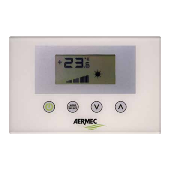
  • Seite 20 Verfahren zum Ändern des Temperatur-Sollwerts: Um den Temperatur-Sollwert der Gebläsekonvektoren im von der VMF-E4X gesteuerten Bereich einzustellen, die nachfolgend beschriebenen Arbeiten ausführen: • Während des normalen Betriebs wird auf dem Display (mit dem Symbol ) die Raumtemperatur angezeigt. AUTO AUTO •...
  • Seite 21: Änderung Der Benutzerparameter

    ÄNDERUNG DER BENUTZERPARAMETER Die Bedientafel VMF-E4X verfügt über sogenannte "Benutzerparameter", die dazu dienen, die Geschwindigkeit der Inverter-Gebläse- konvektoren auszuwählen, wenn letztere in den Betriebsarten V1, V2, V3 arbeiten, und die Position der Klappen für die FCL-Gebläse- AUTO konvektoren mit GLFM-Gitter einzustellen.
  • Seite 22 Fall befinden sich die Raumtemperaturfühler an der kleinen Bedientafel und am Gebläsekonvektor. Für die Einstellung der Raumtemperatur durch den Thermostat kann eine der drei folgenden Konfigurationen gewählt werden. Regelung mit in die VMF-E4X integrierte Sonde; Regelung mit in die Gebläsekonvektoren integrierte Sonde;...
  • Seite 23 AUTO Für die Auswahl der für die spezifische Installation am besten geeigneten Konfiguration müssen nur die drei aus der nachstehenden Abbildung ersicht- lichen Arbeitsschritte durchgeführt werden: Mit dem Parameter FLP (Flaps position) kann man die Position der im motorisierten Gitter GLFxxM vorhandenen Klappen auswählen. MODE SELECT Wenn der Wert zwischen 0 und 100% liegt, verkörpert der Parameter FLP die Position des Leitblechs, beträgt der ausgewählte Wert...
  • Seite 24 Abbildung ersichtlich durchgeführt. Der Stopp dieser Anzeige obliegt immer dem Überwachungssystem. Alarmanzeige Die VMF-E4X sieht die Anzeige einiger Störungen vor, die am Gebläsekonvektor auftreten können. Die Störungen werden mit der Meldung „AL“ ge- folgt von einem Code angezeigt, wie im nachfolgenden Beispiel zu sehen ist:...
  • Seite 25 • APLICACIONES DEL VMF-E4X: APLICACIÓN STAND ALONE: La aplicación más simple para usar el VMF-E4X, prevé un solo fan coil controlado por un solo panel, esta conexión es de tipo Mod Bus TTL, y su máxima longitud puede ser de 30 metros.
  • Seite 26 PROCEDIMIENTO DE CAMBIO DE SET DE TEMPERATURA: Para configurar el set de temperatura de los fan coils en la zona controlada por el VMF-E4X, respetar las siguientes operaciones: AUTO AUTO • Durante el funcionamiento normal, en la pantalla (indicado como icono ) se visualiza la temperatura ambiente.
  • Seite 27 AUTO AUTO MODE MODE SELECT SELECT AUTO Símbolo del parámetro Cambio de valor del parámetro AUTO AUTO Fan Speed en modo V1 MODE MODE SELECT AUTO AUTO (valor de rango 5÷34 %) MODE SELECT SELECT AUTO AUTO AUTO MODE MODE MODE MODE SELECT...
  • Seite 28 Regulación con sonda en el panel E4 Regulación con sonda en el panel del fan coil Regulación con valor promedio de la lectura de las dos sondas Regulación con sonda en el panel E4 sin filtrado software Regulación con valor promedio entre la sonda del fan coil y el valor de la sonda E4 sin filtrado software AUTO Para seleccionar la configuración adecuada a la instalación específica, es suficiente efectuar las tres operaciones siguientes:...
  • Seite 29 VISUALIZACIÓN DE LAS ALARMAS El VMF-E4X prevé la visualización de algunas anomalías que pueden surgir en el fan coil; estos fallos de funcionamiento se indican mediante una cadena “AL” seguida de un código, como se indica en el siguiente ejemplo AUTO Los posibles códigos de alarma son:...
  • Seite 30 VISUALIZACIÓN DE CONDICIONES DE FUNCIONAMIENTO PARTICULARES: A continuación se presenta una tabla que describe brevemente algunas combinaciones de visualizaciones utilizadas para representar condiciones de uso particulares: Estado sím- Símbolo Significado bolo Termostato deshabilitado Modo de funcionamiento del termostato forzado por el supervisor AUTO AUTO Activa el modo SLEEP (para fan coils que llevan el termostato E1 y tienen el changeover del lado agua)
  • Seite 32 AERMEC S.p.A. si riserva la facoltà di apportare in qualsiasi momento tutte le modifiche ritenute necessarie per il miglioramento del prodotto. Les données mentionnées dans ce manuel ne constituent aucun engagement de notre part. Aermec S.p.A. se réserve le droit de modifier à tous moments les données con- sidérées nécessaires à...