Herunterladen Inhalt Inhalt Diese Seite drucken
Inhaltsverzeichnis

Werbung

Verfügbare Sprachen

Verfügbare Sprachen

Quick Start
Thank you for purchasing the MSI
B450 TOMAHAWK MAX
®
motherboard. This Quick Start section provides demonstration
diagrams about how to install your computer. Some of the
installations also provide video demonstrations. Please link to the
URL to watch it with the web browser on your phone or tablet. You
may have even link to the URL by scanning the QR code.
Kurzanleitung
Danke, dass Sie das MSI
B450 TOMAHAWK MAX
Motherboard
®
gewählt haben. Dieser Abschnitt der Kurzanleitung bietet eine Demo
zur Installation Ihres Computers. Manche Installationen bieten
auch die Videodemonstrationen. Klicken Sie auf die URL, um diese
Videoanleitung mit Ihrem Browser auf Ihrem Handy oder Table
anzusehen. Oder scannen Sie auch den QR Code mit Ihrem Handy,
um die URL zu öffnen.
Présentation rapide
Merci d' avoir choisi la carte mère MSI
B450 TOMAHAWK
MAX.
®
Ce manuel fournit une rapide présentation avec des illustrations
explicatives qui vous aideront à assembler votre ordinateur. Des
tutoriels vidéo sont disponibles pour certaines étapes. Cliquez sur
le lien fourni pour regarder la vidéo sur votre téléphone ou votre
tablette. Vous pouvez également accéder au lien en scannant le QR
code qui lui est associé.
Быстрый старт
Благодарим вас за покупку материнской платы MSI
B450
®
MAX. В этом разделе представлена информация,
TOMAHAWK
которая поможет вам при сборке комьютера. Для некоторых
этапов сборки имеются видеоинструкции. Для просмотра
видео, необходимо открыть соответствующую ссылку в
веб-браузере на вашем телефоне или планшете. Вы также
можете выполнить переход по ссылке, путем сканирования
QR-кода.
I
Quick Start

Werbung

Inhaltsverzeichnis
loading

Inhaltszusammenfassung für MSI B450 TOMAHAWK MAX

  • Seite 1 Videoanleitung mit Ihrem Browser auf Ihrem Handy oder Table anzusehen. Oder scannen Sie auch den QR Code mit Ihrem Handy, um die URL zu öffnen. Présentation rapide Merci d’ avoir choisi la carte mère MSI B450 TOMAHAWK MAX. ® Ce manuel fournit une rapide présentation avec des illustrations explicatives qui vous aideront à...
  • Seite 2 Installing a Processor/ Installation des Prozessors/ Installer un processeur/ Установка процессора https://youtu.be/Xv89nhFk1vc CPU_FAN1 Quick Start...
  • Seite 3 If you are installing the screw-type CPU heatsink, please follow the figure below to remove the retention module first and then install the heatsink. Wenn Sie einen CPU-Kühler mit Schraubenbefestigung einsetzen, folgen Sie bitte den Anweisungen unten um das Retention-Modul zu entfernen und den Kühler zu installieren.
  • Seite 4 Installing DDR4 memory/ Installation des DDR4-Speichers/ Installer une mémoire DDR4/ Установка памяти DDR4 http://youtu.be/T03aDrJPyQs DIMMB2 DIMMB2 DIMMB1 DIMMA2 DIMMA2 DIMMA2 DIMMA1 Quick Start...
  • Seite 5 Connecting the Front Panel Header/ Anschließen der Frontpanel-Stiftleiste/ Connecter un connecteur du panneau avant/ Подключение разъемов передней панели http://youtu.be/DPELIdVNZUI Power LED Power Switch JFP1 Reserved HDD LED Reset Switch HDD LED + Power LED + HDD LED - Power LED - Reset Switch Power Switch Reset Switch...
  • Seite 6 Installing the Motherboard/ Installation des Motherboards/ Installer la carte mère/ Установка материнской платы Quick Start...
  • Seite 7 Installing SATA Drives/ Installation der SATA-Laufwerke/ Installer le disque dur SATA/ Установка дисков SATA http://youtu.be/RZsMpqxythc Quick Start...
  • Seite 8 Installing a Graphics Card/ Einbau der Grafikkarte/ Installer une carte graphique/ Установка дискретной видеокарты http://youtu.be/mG0GZpr9w_A VIII Quick Start...
  • Seite 9 Connecting Peripheral Devices/ Peripheriegeräte/ Connecter un périphérique anschliessen/ Подключение периферийных устройств Quick Start...
  • Seite 10 Connecting the Power Connectors/ Stromanschlüsse anschliessen/ Connecter les câbles du module d’ alimentation/ Подключение разъемов питания http://youtu.be/gkDYyR_83I4 ATX_PWR1 CPU_PWR1 Quick Start...
  • Seite 11: Power On/ Einschalten/ Mettre Sous-Tension/ Включение Питания

    Power On/ Einschalten/ Mettre sous-tension/ Включение питания Quick Start...
  • Seite 12 NOTE Quick Start...
  • Seite 13: Inhaltsverzeichnis

    Contents Safety Information ....................2 Specifications ......................3 Package contents ....................8 Rear I/O Panel ....................... 9 LAN Port LED Status Table..................9 Audio Ports Configuration ..................9 Realtek Audio Console ..................10 Overview of Components ..................12 Processor Socket ....................13 DIMM Slots ......................
  • Seite 14: Safety Information

    Safety Information y The components included in this package are prone to damage from electrostatic discharge (ESD). Please adhere to the following instructions to ensure successful computer assembly. y Ensure that all components are securely connected. Loose connections may cause the computer to not recognize a component or fail to start.
  • Seite 15: Specifications

    Dual channel memory architecture y Supports non-ECC UDIMM memory y Supports ECC UDIMM memory (non-ECC mode) * Please refer www.msi.com for more information on compatible memory. y 1x PCIe 3.0 x16 slot (PCI_E1) ƒ 1st, 2nd and 3rd Gen AMD Ryzen™ processors support x16 speed ƒ...
  • Seite 16 Continued from previous page ® y 2x SATA 6Gb/s ports* y 1x M.2 slot (Key M)* ƒ Supports PCIe 3.0 x4 (1st, 2nd and 3rd Gen AMD Ryzen™, Ryzen™ with Radeon™ Vega Graphics and 2nd Gen AMD Ryzen™ with Radeon™ Graphics) or PCIe 3.0 x2 Storage (Athlon™...
  • Seite 17 Continued from previous page y 1x Flash BIOS Button y 1x PS/2 keyboard/ mouse combo port y 2x USB 2.0 Type-A ports y 1x DVI-D port y 1x HDMI port ™ Back Panel Connectors y 2x USB 3.2 Gen1 Type-A ports y 1x LAN (RJ45) port y 1x USB 3.2 Gen2 Type-A port y 1x USB 3.2 Gen2 Type-C port...
  • Seite 18 SMART TOOL y RAMDISK Software y X-BOOST y GAMING APP y MYSTIC LIGHT y Open Broadcaster Software (OBS) y CPU-Z MSI GAMING y Norton Internet Security Solution ™ y Google Chrome , Google Toolbar, Google Drive ™ y Audio ƒ...
  • Seite 19 Continued from previous page y LED ƒ Mystic Light ƒ Mystic Light Extension (RGB) ƒ Mystic light SYNC ƒ EZ DEBUG LED y Protection ƒ PCIe Steel Armor ƒ PCIe Steel Slot y Performance ƒ Multi GPU-CrossFire Technology ƒ DDR4 Boost ƒ...
  • Seite 20: Package Contents

    Package contents Please check the contents of your motherboard package. It should contain: y Motherboard y Driver DVD y User Manual y Quick Installation Guide y I/O Shielding y SATA 6G Cable x2 y Case Badge y Product Registration Card y M.2 Screw x1 Important If any of the above items are damaged or missing, please contact your retailer.
  • Seite 21: Rear I/O Panel

    Rear I/O Panel Audio Ports USB 3.2 Gen1 Type-A PS/2 Flash BIOS Port DVI-D USB 3.2 Gen2 USB 2.0 Type-A Type-A Flash BIOS Button USB 3.2 Gen2 Type-C y Flash BIOS Port/ Button - Please refer to page 26 for Updating BIOS with Flash BIOS Button.
  • Seite 22: Realtek Audio Console

    Realtek Audio Console After Realtek Audio Console is installed. You can use it to change sound settings to get better sound experience. Application Enhancement Device Selection Main Volume Jack Status y Device Selection - allows you to select a audio output source to change the related options.
  • Seite 23 Audio jacks to headphone and microphone diagram Audio jacks to stereo speakers diagram AUDIO INPUT Audio jacks to 7.1-channel speakers diagram AUDIO INPUT Rear Front Side Center/ Subwoofer Rear I/O Panel...
  • Seite 24: Overview Of Components

    Overview of Components Processor Socket DIMMA1 DIMMA2 CPU_FAN1 SYS_FAN1 DIMMB1 CPU_PWR1 DIMMB2 JRGB2 PUMP_FAN1 SYS_FAN3 ATX_PWR1 SYS_FAN4 M2_1 PCI_E1 PCI_E2 SATA▼5▲6 PCI_E3 SATA▼3▲4 PCI_E4 PCI_E5 JBAT1 JCI1 SATA1 JAUD1 JRGB1 SYS_FAN2 SATA2 JCOM1 JUSB3 JTPM1 JUSB2 JUSB1 JFP2 JFP1 Overview of Components...
  • Seite 25: Processor Socket

    This motherboard is designed to support overclocking. Before attempting to overclock, please make sure that all other system components can tolerate overclocking. Any attempt to operate beyond product specifications is not recommended. MSI does not guarantee the damages or risks caused by inadequate ®...
  • Seite 26: Dimm Slots

    Due to AM4 processor/memory controller official specification limitation, the frequency of memory modules may operate lower than the marked value under the default state. Please refer www.msi.com for more information on compatible memory. Overview of Components...
  • Seite 27: Pci_E1~5: Pcie Expansion Slots

    *** For Athlon™ with Radeon Vega Graphics processors Important If you install a large and heavy graphics card, you need to use a tool such as MSI Gaming Series Graphics Card Bolster to support its weight to prevent deformation of the slot.
  • Seite 28: M2_1: M.2 Slot (Key M)

    M2_1: M.2 Slot (Key M) Video Demonstration Watch the video to learn how to Install M.2 module. http://youtu.be/JCTFABytrYA Installing M.2 SSD 1. Loosen the M.2 riser screw from the 3. Insert your M.2 SSD into the M.2 motherboard. slot at a 30-degree angle. 2.
  • Seite 29: Sata1~6: Sata 6Gb/S Connectors

    SATA1~6: SATA 6Gb/s Connectors These connectors are SATA 6Gb/s interface ports. Each connector can connect to one SATA device. SATA6 SATA5 SATA4 SATA3 SATA2 SATA1 Important Please do not fold the SATA cable at a 90-degree angle. Data loss may result during transmission otherwise.
  • Seite 30: Cpu_Pwr1, Atx_Pwr1: Power Connectors

    CPU_PWR1, ATX_PWR1: Power Connectors These connectors allow you to connect an ATX power supply. CPU_PWR1 Ground +12V Ground +12V Ground +12V Ground +12V +3.3V +3.3V +3.3V -12V Ground Ground PS-ON# Ground Ground Ground ATX_PWR1 Ground Ground PWR OK 5VSB +12V +12V +3.3V Ground...
  • Seite 31: Jusb1~2: Usb 2.0 Connectors

    JUSB1~2: USB 2.0 Connectors These connectors allow you to connect USB 2.0 ports on the front panel. USB0- USB1- USB0+ USB1+ Ground Ground No Pin Important Note that the VCC and Ground pins must be connected correctly to avoid possible damage.
  • Seite 32: Cpu_Fan1, Pump_Fan1, Sys_Fan1~4: Fan Connectors

    CPU_FAN1, PUMP_FAN1, SYS_FAN1~4: Fan Connectors Fan connectors can be classified as PWM (Pulse Width Modulation) Mode or DC Mode. PWM Mode fan connectors provide constant 12V output and adjust fan speed with speed control signal. DC Mode fan connectors control fan speed by changing voltage. When you plug a 3-pin (Non-PWM) fan to a fan connector in PWM mode, the fan speed will always maintain at 100%, which might create a lot of noise.
  • Seite 33: Jci1: Chassis Intrusion Connector

    JCI1: Chassis Intrusion Connector This connector allows you to connect the chassis intrusion switch cable. Normal Trigger the chassis (default) intrusion event Using chassis intrusion detector 1. Connect the JCI1 connector to the chassis intrusion switch/ sensor on the chassis. 2.
  • Seite 34: Jtpm1: Tpm Module Connector

    JTPM1: TPM Module Connector This connector is for TPM (Trusted Platform Module). Please refer to the TPM security platform manual for more details and usages. LPC Clock 3V Standby power LPC Reset 3.3V Power LPC address & data pin0 Serial IRQ LPC address &...
  • Seite 35: Jrgb1~2: Rgb Led Connectors

    Always turn off the power supply and unplug the power cord from the power outlet before installing or removing the RGB LED strip. Please use MSI’ s software to control the extended LED strip. EZ Debug LEDs These LEDs indicate the status of key components during booting process. When an error is occurred, the corresponding LED stays lit until the problem is solved.
  • Seite 36: Bios Setup

    BIOS Setup The default settings offer the optimal performance for system stability in normal conditions. You should always keep the default settings to avoid possible system damage or failure booting unless you are familiar with BIOS. Important BIOS items are continuously update for better system performance. Therefore, the description may be slightly different from the latest BIOS and should be for reference only.
  • Seite 37: Resetting Bios

    Updating BIOS Updating BIOS with M-FLASH Before updating: Please download the latest BIOS file that matches your motherboard model from MSI website. And then save the BIOS file into the USB flash drive. Updating BIOS: 1. Press Del key to enter the BIOS Setup during POST.
  • Seite 38 Before updating: Please download the latest BIOS file that matches your motherboard model from MSI ® website and rename the BIOS file to MSI.ROM. And then, save the MSI.ROM file to the root of USB flash drive. Important Only the FAT32 format USB flash drive supports updating BIOS by Flash BIOS Button.
  • Seite 39: Ez Mode

    EZ Mode At EZ mode, it provides the basic system information and allows you to configure the basic setting. To configure the advanced BIOS settings, please enter the Advanced Mode by pressing the Setup Mode switch or F7 function key. Screenshot A-XMP switch Setup Mode switch...
  • Seite 40 y Information display - click on the CPU, Memory, Storage, Fan Info and Help buttons on left side to display related information. y Function buttons - enable or disable the LAN Option ROM, HD audio controller, AHCI/RAID, CPU Fan Fail Warning Control, Windows 10 WHQL support and BIOS Log Review by clicking on their respective button.
  • Seite 41: Advanced Mode

    Advanced Mode Press Setup Mode switch or F7 function key can switch between EZ Mode and Advanced Mode in BIOS setup. Screenshot A-XMP switch Setup Mode switch Search Language System information GAME BOOST switch Boot device priority bar BIOS menu BIOS menu selection selection...
  • Seite 42: Oc Menu

    OC Menu This menu is for advanced users who want to overclock the motherboard. Important Overclocking your PC manually is only recommended for advanced users. Overclocking is not guaranteed, and if done improperly, it could void your warranty or severely damage your hardware. If you are unfamiliar with overclocking, we advise you to use GAME BOOST function for easy overclocking.
  • Seite 43 f DRAM Frequency [Auto] Sets the DRAM frequency. Please note the overclocking behavior is not guaranteed. f Adjusted DRAM Frequency Shows the adjusted DRAM frequency. Read-only. f Memory Try It ! [Disabled] It can improve memory compatibility or performance by choosing optimized memory preset.
  • Seite 44 fVR 12VIN OCP Expander [Auto] Expands the limitation of VR Over Current Protection with 12V input voltage. The higher expanding value indicates less protection. Therefore, please adjust the current carefully if needed, or it may damage the CPU/ VR MOS. If set to "Auto", BIOS will configure this setting automatically.
  • Seite 45 fIOMMU Mode (optional) Enables/disables the IOMMU (I/O Memory Management Unit) for I/O Virtualization. fSpread Spectrum (optional) This function reduces the EMI (Electromagnetic Interference) generated by modulating clock generator pulses. [Enabled] Enables the spread spectrum function to reduce the EMI (Electromagnetic Interference) problem. [Disabled] Enhances the overclocking ability of CPU Base clock.
  • Seite 46: Software Description

    Software Description Please download and update the latest utilities and drivers at www.msi.com ® Installing Windows 1. Power on the computer. 2. Insert the Windows ® 10 installation disc/USB into your computer. 3. Press the Restart button on the computer case.
  • Seite 47 Inhalt Sicherheitshinweis ....................2 Spezifikationen ...................... 3 Packungsinhalt ...................... 8 Rückseite E/A ......................9 LAN Port LED Zustandstabelle ................9 Konfiguration der Audioanschlüsse ............... 9 Realtek Audio Console ..................10 Übersicht der Komponenten ................12 Prozessorsockel ....................13 DIMM Steckplätze ....................14 PCI_E1~5: PCIe Erweiterungssteckplätze ............
  • Seite 48: Sicherheitshinweis

    Sicherheitshinweis y Die im Paket enthaltene Komponenten sind der Beschädigung durch elektrostatischen Entladung (ESD). Beachten Sie bitte die folgenden Hinweise, um die erfolgreichen Computermontage sicherzustellen. y Stellen Sie sicher, dass alle Komponenten fest angeschlossen sind. Lockere Steckverbindungen können Probleme verursachen, zum Beispiel: Der Computer erkennt eine Komponente nicht oder startet nicht.
  • Seite 49: Spezifikationen

    Dual-Kanal-Speicherarchitektur Speicher y Unterstützt non-ECC UDIMM-Speicher y Unterstützt ECC UDIMM-Speicher (non-ECC Modus) * Weitere Informationen zu kompatiblen Speicher finden Sie unter: http://www.msi.com y 1x PCIe 3.0 x16-Steckplatz (PCI_E1) ƒ AMD Ryzen der 1., 2. und 3. Generation Prozessoren ™...
  • Seite 50: Aufbewahrung

    Fortsetzung der vorherigen Seite ® y 2x SATA 6Gb/s Anschlüsse* y 1x M.2 Steckplatz (Key M)* ƒ Unterstützt PCIe 3.0 x4 (AMD Ryzen der 1., 2. und ® 3. Generation Prozessoren, Ryzen Prozessoren mit ™ Radeon Vega Grafikprozessor und AMD Ryzen der 2.
  • Seite 51 Fortsetzung der vorherigen Seite y 1x Flash BIOS Taste y 1x PS/2 Tastatur/ Maus-Combo-Anschluss y 2x USB 2.0 Typ-A Anschlüsse y 1x DVI-D Anschluss y 1x HDMI Anschluss ™ Hintere Ein-/ und Ausgänge y 2x USB 3.2 Gen1 Typ-A Anschlüsse y 1x LAN (RJ45) Anschluss y 1x USB 3.2 Gen2 Typ-A Anschluss y 1x USB 3.2 Gen2 Typ-C Anschluss...
  • Seite 52: Besondere Funktionen

    SMART TOOL y RAMDISK Software y X-BOOST y GAMING APP y MYSTIC LIGHT y Open Broadcaster Software (OBS) y CPU-Z MSI GAMING y Norton Internet Security Solution ™ y Google Chrome , Google Toolbar, Google Drive ™ y Audio ƒ...
  • Seite 53 Fortsetzung der vorherigen Seite y LED ƒ Mystic Light ƒ Mystic Light Extension (RGB) ƒ Mystic Light SYNC ƒ EZ DEBUG LED y Schutz ƒ PCIe Steel Armor ƒ PCIe Steel Steckplatz y Leistung ƒ Multi GPU-CrossFire Technologie ƒ DDR4 Boost ƒ...
  • Seite 54: Packungsinhalt

    Packungsinhalt Überprüfen Sie den Packungsinhalt des Mainboards. Die Packung sollte enthalten : y Motherboard y Treiber-DVD y Benutzerhandbuch y Schnellinstallationsanleitung y Anschlussblende y SATA 6G Kabel x2 y Gehäuse-Aufkleber y Produktregistrierungskarte y M.2 Schraube x1 Wichtig Falls einer der oben aufgeführten Artikel beschädigt ist oder fehlt, wenden Sie sich bitte an Ihren Händler.
  • Seite 55: Rückseite E/A

    Rückseite E/A Audioanschlüsse USB 3.2 Gen1 Typ-A PS/2 Flash BIOS Anschluss DVI-D USB 3.2 Gen2 USB 2.0 Typ-A Typ-A Flash BIOS Taste USB 3.2 Gen2 Typ-C y Flash BIOS Anschluss/ Taste - Auf der Seite 26 finden Sie eine Anleitung für eine BIOS-Aktualisierung per Flash BIOS Taste.
  • Seite 56: Realtek Audio Console

    Realtek Audio Console Nach der Installation des Realtek Audio Console-Treibers, können Sie die Audioeinstellungen verändern, um ein optimales Klangerlebnis erzeugen. Optimierungen Geräteauswahl Lautstärke Verbindungsstatus y Geräteauswahl - Ermöglicht die Auswahl der Audio-Ausgangs Quelle. Das aktuell aktivierte Gerät ist mit einem Haken gekennzeichnet. y Optimierungen - Die Vielfalt an Optionen bietet eine komplette Anleitung von erwarteten Sound-Effekt für beide Ausgangs- und Eingangsvorrichtung.
  • Seite 57: Audiobuchsen Für Stereo-Lautsprecher

    Audiobuchsen für den Anschluss von einem Kopfhörer und Mikrofon Audiobuchsen für Stereo-Lautsprecher AUDIO INPUT Audiobuchsen für 7.1 Kanal Anlage AUDIO INPUT Rear Front Side Center/ Subwoofer Rückseite E/A...
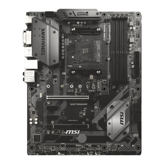
  • Seite 58: Übersicht Der Komponenten

    Übersicht der Komponenten Prozessorsockel DIMMA1 DIMMA2 CPU_FAN1 SYS_FAN1 DIMMB1 CPU_PWR1 DIMMB2 JRGB2 PUMP_FAN1 SYS_FAN3 ATX_PWR1 SYS_FAN4 M2_1 PCI_E1 PCI_E2 SATA▼5▲6 PCI_E3 SATA▼3▲4 PCI_E4 PCI_E5 JBAT1 JCI1 SATA1 JAUD1 JRGB1 SYS_FAN2 SATA2 JCOM1 JUSB3 JTPM1 JUSB2 JUSB1 JFP2 JFP1 Übersicht der Komponenten...
  • Seite 59 Sie jedoch bitte sicher, dass die betroffenen Komponenten mit den abweichenden Einstellungen während des Übertaktens zurecht kommen. Von jedem Versuch des Betriebes außerhalb der Produktspezifikationen kann nur abgeraten werden. MSI übernehmt keinerlei Garantie für die Schäden und Risiken, die aus einem unzulässigem Betrieb oder einem Betrieb außerhalb der Produktspezifikation resultieren.
  • Seite 60: Dimm Steckplätze

    CPU und den installierten Geräten. Speichermodule können auf Basis der offizielle Spezifikation der AM4 CPU/ Speicher-Controller mit einer niedrigeren Frequenz unter dem Standardzustand arbeiten. Weitere Informationen zu kompatiblen Speichermodulen finden Sie unter: http://www.msi.com. Übersicht der Komponenten...
  • Seite 61: Pci_E1~5: Pcie Erweiterungssteckplätze

    PCI_E1~5: PCIe Erweiterungssteckplätze PCI_E1: PCIe 3.0 x16*/ PCIe 3.0 x8**/ PCIe 3.0 x4*** PCI_E2: PCIe 2.0 x1 PCI_E3: PCIe 2.0 x1 PCI_E4: PCIe 2.0 x4 PCI_E5: PCIe 2.0 x1 * Für AMD Ryzen der 1., 2. und 3. Generation Prozessoren ™...
  • Seite 62: M2_1: M.2 Steckplatz (Key M)

    M2_1: M.2 Steckplatz (Key M) Video-Demonstration Eine anschauliche Darstellung zur Installation eines M.2 Moduls finden Sie im Video. http://youtu.be/JCTFABytrYA Installation einer M.2 SSD 1. Lösen Sie die M.2-Schraube aus dem 4. Schrauben Sie die M.2-SSD mit Motherboard. der mitgelieferten M.2-Schraube fest.
  • Seite 63: Sata1~6: Sata 6Gb/S Anschlüsse

    SATA1~6: SATA 6Gb/s Anschlüsse Dieser Anschluss basiert auf der Hochgeschwindigkeitsschnittstelle SATA 6 Gb/s. Pro Anschluss kann ein SATA Gerät angeschlossen werden. SATA6 SATA5 SATA4 SATA3 SATA2 SATA1 Wichtig Knicken Sie das SATA-Kabel nicht in einem 90° Winkel. Datenverlust könnte die Folge sein.
  • Seite 64: Cpu_Pwr1, Atx_Pwr1: Stromanschlüsse

    CPU_PWR1, ATX_PWR1: Stromanschlüsse Mit diesen Anschlüssen verbinden Sie die ATX Stromstecker. CPU_PWR1 Ground +12V Ground +12V Ground +12V Ground +12V +3.3V +3.3V +3.3V -12V Ground Ground PS-ON# Ground Ground Ground ATX_PWR1 Ground Ground PWR OK 5VSB +12V +12V +3.3V Ground Wichtig Stellen Sie sicher, dass alle Anschlüsse mit den richtigen Anschlüssen des Netzteils verbunden sind, um einen stabilen Betrieb der Hauptplatine sicherzustellen.
  • Seite 65: Jusb1~2: Usb 2.0 Anschlüsse

    Bitte beachten Sie, dass Sie die mit VCC (Stromführende Leitung) und Ground (Erdleitung) bezeichneten Pins korrekt verbinden müssen, ansonsten kann es zu Schäden kommen. Um ein iPad, iPhone und einen iPod über USB-Anschlüsse aufzuladen, installieren Sie bitte die MSI SUPER CHARGER Software. ® JUSB3: USB 3.2 Gen1 Anschluss Mit diesem Anschluss können Sie den USB 3.2 Gen1 Anschluss auf dem Frontpanel...
  • Seite 66: Cpu_Fan1, Pump_Fan1, Sys_Fan1~4: Stromanschlüsse Für Lüfter

    CPU_FAN1, PUMP_FAN1, SYS_FAN1~4: Stromanschlüsse für Lüfter Diese Anschlüsse können im PWM (Pulse Width Modulation) Modus oder Spannungsmodus betrieben werden. Im PWM-Modus bieten die Lüfteranschlüsse konstante 12V Ausgang und regeln die Lüftergeschwindigkeit per Drehzahlsteuersignal. Im DC-Modus bestimmen die Lüfteranschlüsse die Lüftergeschwindigkeit durch Ändern der Spannung. Wenn Sie ein 3-Pin (Non-PWM) Lüfter an einen PWM-Modus Lüfteranschluss anschließen, läuft der Lüfter mit höchster Drehzahl und kann unangenehm laut werden.
  • Seite 67: Jci1: Gehäusekontaktanschluss

    JCI1: Gehäusekontaktanschluss Dieser Anschluss wird mit einem Kontaktschalter verbunden. Normal Löse den (Standardwert) Gehäuseeingriff aus Gehäusekontakt-Detektor verwenden 1. Schließen Sie den JCI1-Anschluss am Gehäusekontakt-Schalter/ Sensor am Gehäuse an. 2. Schließen Sie die Gehäuseabdeckung. 3. Gehen Sie zu BIOS > SETTINGS > Security > Chassis Intrusion Configuration. 4.
  • Seite 68: Jtpm1: Tpm Anschluss

    JTPM1: TPM Anschluss Dieser Anschluss wird für das TPM Modul (Trusted Platform Module) verwendet. Weitere Informationen über den Einsatz des optionalen TPM Modules entnehmen Sie bitte dem TPM Plattform Handbuch. LPC Clock 3V Standby power LPC Reset 3.3V Power LPC address & data pin0 Serial IRQ LPC address &...
  • Seite 69: Jrgb1~2: Rgb Led Anschlüsse

    Schalten Sie die Stromversorgung aus und ziehen Sie das Netzkabel ab, bevor Sie die RGB-LED-Streifen ein- und ausbauen. Bitte verwenden Sie die MSI-Software zur Steuerung des LED-Leuchtstreifens. EZ Debug LEDs Diese LEDs zeigen den Status der Hauptkomponenten während des Boot-Vorgangs an Im Falle eines Fehlers, leuchtet die entsprechende LED bis zur Lösung des Problems...
  • Seite 70: Bios-Setup

    BIOS-Setup Die Standardeinstellungen bieten die optimale Leistung für die Systemstabilität unter Normalbedingungen. Sie sollten immer die Standardeinstellungen behalten, um mögliche Schäden des Systems oder Boot-Fehler zu vermeiden, außer Sie besitzen ausreichende BIOS Kenntnisse. Wichtig BIOS Funktionen werden für eine bessere Systemleistung kontinuierlich aktualisiert. Deswegen können die Beschreibungen leicht von der letzten Fassung des BIOS abweichen und sollten demnach nur als Anhaltspunkte dienen.
  • Seite 71: Reset Des Bios

    Before updating: Vorbereitung: Laden Sie bitte die neueste BIOS Version, die dem Motherboard-Modell entspricht, von der offiziellen MSI Website herunter und speichern Sie die BIOS-Datei auf USB-Flash- Laufwerk. BIOS-Aktualisierungsschritte: 1. Drücken Sie während des POST-Vorgangs die Taste (Entf), um das BIOS zu öffnen.
  • Seite 72 Aktualisierung des BIOS mit Flash BIOS Taste Vorbereitung: Laden Sie bitte die neueste BIOS Version, die das Modell des Motherboards entspricht, von der offiziellen MSI Website und benennen die BIOS-Datei im MSI.ROM um. Und speichern Sie die MSI.ROM-Datei im Root-Verzeichnis des USB-Flash-Speichers. Wichtig Nur USB-Flashlaufwerke im FAT32-Format unterstützen einen BIOS-Update per Flash...
  • Seite 73: Ez Modus

    EZ Modus Im EZ-Modus können Sie die Grundinformationen des Systems einsehen und grundlegende Einstellungen konfigurieren. Um sich die erweiterten BIOS- Einstellungen anzeigen zu lassen, aktivieren Sie bitte den Erweiterten Modus durch Drücken des Setup Modus Schalter oder der Funktionstaste F7. Screenshot A-XMP Schalter Setup Modus Schalter...
  • Seite 74 y Systeminformationen - Diese zeigt CPU/ DDR-Frequenz, CPU/ MB-Temperatur, MB/ CPU-Typ, Speicherkapazität, CPU/ DDR-Spannung, BIOS-Version und Erstellungs- Datum. y Boot-Geräte Prioritätsleiste - Sie können die Gerätesymbole verschieben, um die Startreihenfolge zu ändern. Die Bootreihenfolge sind mit “hoch” (links) bis “niedrig” (rechts) bezeichnet.
  • Seite 75: Erweiterter Modus

    Erweiterter Modus Drücken Sie den Setup Modus Schalter oder die Funkionstaste F7, um zwischen dem EZ-Modus und Erweiterten-Modus im BIOS-Setup zu wechseln. Screenshot A-XMP Schalter Setup Modus Schalter Suchen Sprache System- information GAME BOOST Schalter Bootgeräte- Prioritätsleiste BIOS-Menü BIOS-Menü -Auswahl -Auswahl Menüanzeige y GAME BOOST Schalter/ Setup Modus Schalter/ Screenshot/ Sprache/...
  • Seite 76: Oc Menü

    OC Menü In diesem Menü können Benutzer das BIOS anpassen und das Mainboard übertakten. Bitte führen Sie nur Änderungen durch, wenn Sie sich über das Ergebnis im Klaren sind. Sie sollten Erfahrung beim Übertakten haben, da Sie sonst das Motherboard oder Komponenten des Systems beschädigen können.
  • Seite 77 f A-XMP [Disabled] Aktivieren Sie die A-XMP Funktion oder wählen Sie ein Profil des Speichermoduls aus, um den Speicher zu übertakten. Diese Option erscheint nur, wenn die installierten Speichermodule/ das installierte Motherboard diese Funktion unterstützen. f DRAM Frequency [Auto] Setzen Sie die DRAM Frequenz. Bitte beachten Sie, dass ein zuverlässiges Übertaktungsverhalten nicht garantiert werden kann.
  • Seite 78 fCPU Under Voltage Protection [Auto] Legen Sie die Spannungsgrenze für den CPU-Unterspannungsschutz fest. Wenn die Einstellung auf Auto gesetzt ist, wird das BIOS diese Einstellungen automatisch konfigurieren. Höhere Spannung bietet weniger Schutz und kann das System beschädigen. fCPU Over Current Protection [Auto] Legen Sie den aktuellen Grenzwert für den CPU-Überstromschutz fest.
  • Seite 79 fDIMMx Memory SPD Drücken Sie die Eingabetaste <Enter>, um das Untermenü aufzurufen. Das Untermenü zeigt die Informationen des verwendeten Speichers an. Nur Anzeige. f CPU Features Drücken Sie die Eingabetaste <Enter>, um das Untermenü aufzurufen. fGlobal C-state Control [Enabled] (optional) Aktiviert oder deaktiviert die IO-basierten C-States und DF C-States.
  • Seite 80 fAMD Cool’ n’ Quiet [Enabled] Die Cool’ n’ Quiet-Technologie kann die CPU-Geschwindigkeit und den Stromverbrauch effizient und dynamisch herabsetzen. fSVM Mode [Disabled] Aktiviert oder deaktiviert den AMD SVM (Secure Virtual Machine) Modus. fBIOS PSP Support [Enabled] (optional) Aktiviert oder deaktiviert die Funktion BIOS PSP Support. Es steuert den PSP- Unterpunkt einschließlich C2P/ P2C-Mailbox, Secure-S3 und fTPM-Support.
  • Seite 81: Softwarebeschreibung

    Sie DVDSetup.exe starten aus, um den Installer zu öffnen. Wenn Sie die AutoPlay-Funktionen in der Windows-Systemsteuerung ausschalten, können Sie das Programm DVD Setup.exe im Hauptverzeichnis der MSI Treiber CD auch manuell ausführen. 4. Der Installer wird findet eine Liste aller benötigten Treiber auf der Treiber/ Software-Registerkarte.
  • Seite 83 Table des matières Informations de sécurité ..................2 Spécifications ......................3 Contenu ........................8 Panneau arrière Entrée / Sortie ................9 Tableau explicatif de l’ état de la LED du port LAN ..........9 Configuration des ports audio ................9 Realtek Audio Console ..................
  • Seite 84: Informations De Sécurité

    Informations de sécurité y Les composants dans l’ emballage peuvent être endommagés par des décharges électrostatiques (ESD). Pour vous assurer de correctement monter votre ordinateur, veuillez vous référer aux instructions ci-dessous. y Assurez-vous de bien connecter tous les composants. En cas de mauvaise connexion, il se peut que l’...
  • Seite 85: Spécifications

    Architecture mémoire double canal y Support mémoire non-ECC UDIMM y Support mémoire ECC UDIMM (mode non-ECC) * Veuillez vous référer au site www.msi.com pour plus d’ informations sur la mémoire compatible. y 1 x slot PCIe 3.0 x 16 (PCI_E1) ƒ...
  • Seite 86 Suite du tableau de la page précédente Processeur AMD ® y 2 x ports SATA 6 Gb/s* y 1 x slot M.2 (Touche M)* ƒ Support PCIe 3.0 x 4 (AMD Ryzen™ de 1ère, 2ème et 3ème génération / Ryzen™ avec cœurs graphiques Radeon™...
  • Seite 87 Suite du tableau de la page précédente y 1 x bouton Flash BIOS y 1 x port combo clavier / souris PS/2 y 2 x ports USB 2.0 Type-A y 1 x port DVI-D y 1 x port HDMI ™ Connecteurs sur le panneau arrière y 2 x ports USB 3.2 Gen1 Type-A...
  • Seite 88 SMART TOOL y RAMDISK Logiciel y X-BOOST y GAMING APP y MYSTIC LIGHT y Open Broadcaster Software (OBS) y CPU-Z MSI GAMING y Norton Internet Security Solution ™ y Google Chrome , Google Toolbar et Google Drive ™ y Audio ƒ...
  • Seite 89 Suite du tableau de la page précédente y LED ƒ Mystic Light ƒ Mystic Light Extension (RGB) ƒ Mystic light SYNC ƒ EZ DEBUG LED y Protection ƒ Steel Armor PCIe ƒ Steel Slot PCIe y Performance ƒ Technologie Multi GPU-CrossFire ƒ...
  • Seite 90: Contenu

    Contenu Vérifiez tous les articles dans le carton d’ emballage de votre carte mère. L’ emballage doit contenir : y Carte mère y DVD de pilotes y Manuel d’ utilisation y Guide d’ installation rapide y Protection I/O Shielding y Câble SATA 6G x 2 y Insigne pour châssis y Carte d’...
  • Seite 91: Panneau Arrière Entrée / Sortie

    Panneau arrière Entrée / Sortie Ports audio USB 3.2 Gen1 Type-A PS/2 Port Flash BIOS DVI-D USB 3.2 Gen2 USB 2.0 Type-A Type-A Bouton Flash BIOS USB 3.2 Gen2 Type-C y Port / Bouton Flash BIOS - Veuillez vous référer à la page 26 pour en savoir plus sur la mise à...
  • Seite 92: Realtek Audio Console

    Realtek Audio Console Après l’ installation de Realtek Audio Console, vous pouvez l’ utiliser pour modifier les paramètres du son afin d’ obtenir une meilleure expérience sonore. Amélioration d’ application Sélection du périphérique Volume principal Etat des prises Jack y Sélection du périphérique - vous permet de sélectionner une source de sortie audio pour en modifier les paramètres.
  • Seite 93 Illustration de l’ utilisation des ports audio dédiés au casque et au microphone Illustration de l’ utilisation du port audio dédié aux haut-parleurs AUDIO INPUT Illustration de l’ utilisation des ports audio dédiés aux haut-parleurs 7.1 AUDIO INPUT Rear Front Side Center/ Subwoofer...
  • Seite 94: Vue D' Ensemble Des Composants

    Vue d’ ensemble des composants Socket processeur DIMMA1 DIMMA2 CPU_FAN1 SYS_FAN1 DIMMB1 CPU_PWR1 DIMMB2 JRGB2 PUMP_FAN1 SYS_FAN3 ATX_PWR1 SYS_FAN4 M2_1 PCI_E1 PCI_E2 SATA▼5▲6 PCI_E3 SATA▼3▲4 PCI_E4 PCI_E5 JBAT1 JCI1 SATA1 JAUD1 JRGB1 SYS_FAN2 SATA2 JCOM1 JUSB3 JTPM1 JUSB2 JUSB1 JFP2 JFP1 Vue d’...
  • Seite 95: Socket Processeur

    Cette carte mère supporte l’ overclocking. Néanmoins, veuillez vous assurer que vos composants soient capables de tolérer l’ overclocking. Prenez note que l’ utilisation au-delà des spécifications du constructeur n’ est pas recommandée. MSI ne garantit ®...
  • Seite 96: Slots Dimm

    Du fait des limites officiels des spécifications du contrôleur CPU / mémoire AM4, les modules de mémoire peuvent fonctionner à une fréquence réduite par rapport à la valeur indiquée en mode défaut. Veuillez vous référer au site www.msi.com pour plus d’ informations sur la mémoire compatible.
  • Seite 97: Pci_E1~5 : Slots D' Extension Pcie

    Important Si vous installez une carte graphique lourde, il vous faut utiliser un outil comme la barre de support MSI Gaming Series pour supporter son poids et pour éviter la déformation du slot. Si vous choisissez d’ installer une seule carte d’ extension PCIe x 16, nous vous recommandons d’...
  • Seite 98: M2_1 : Slot M.2 (Touche M)

    M2_1 : Slot M.2 (Touche M) Vidéo de démonstration Référez-vous à la vidéo d’ instruction sur l’ installation du module M.2. http://youtu.be/JCTFABytrYA Installation du SSD M.2 1. Desserrez la vis M.2 de la carte mère. 3. Insérez votre SSD M.2 dans le slot M.2 à...
  • Seite 99: Sata1~6 : Connecteurs Sata 6 Gb/S

    SATA1~6 : Connecteurs SATA 6 Gb/s Ces connecteurs utilisent une interface SATA 6 Gb/s. Chaque connecteur peut être relié à un appareil SATA. SATA6 SATA5 SATA4 SATA3 SATA2 SATA1 Important Veuillez ne pas plier les câbles SATA à 90° car cela pourrait entraîner une perte de données pendant la transmission.
  • Seite 100: Cpu_Pwr1, Atx_Pwr1 : Connecteurs D' Alimentation

    CPU_PWR1, ATX_PWR1 : Connecteurs d’ alimentation Ces connecteurs vous permettent de relier une alimentation ATX. CPU_PWR1 Ground +12V Ground +12V Ground +12V Ground +12V +3.3V +3.3V +3.3V -12V Ground Ground PS-ON# Ground Ground Ground ATX_PWR1 Ground Ground PWR OK 5VSB +12V +12V +3.3V...
  • Seite 101: Jusb1~2 : Connecteurs Usb 2.0

    Notez que les broches VCC et Terre doivent être branchées correctement afin d’ éviter tout dommage sur la carte mère. Pour recharger votre iPad, iPhone et iPod par l’ intermédiaire d’ un port USB, veuillez installer l’ utilitaire MSI SUPER CHARGER. ®...
  • Seite 102: Cpu_Fan1, Pump_Fan1, Sys_Fan1~4 : Connecteurs Pour Ventilateurs

    CPU_FAN1, PUMP_FAN1, SYS_FAN1~4 : Connecteurs pour ventilateurs Les connecteurs pour ventilateurs peuvent être utilisés en mode PWM (Pulse Width Modulation) et en mode DC. En mode PWM, les connecteurs fournissent une sortie de 12V constante et ajustent la vitesse des ventilateurs avec un signal de contrôle de vitesse.
  • Seite 103: Jci1 : Connecteur Intrusion Châssis

    JCI1 : Connecteur intrusion châssis Ce connecteur est relié à un câble d’ interrupteur intrusion châssis. Normal Commencer l’ activité intrusion châssis (défaut) Utilisation du détecteur d’ intrusion châssis 1. Reliez le connecteur JCI1 à l’ interrupteur ou au capteur d’ intrusion châssis situé sur le boîtier du PC.
  • Seite 104: Jtpm1 : Connecteur De Module Tpm

    JTPM1 : Connecteur de module TPM Ce connecteur est relié à un module TPM (Trusted Platform Module). Veuillez vous référer au manuel du module TPM pour plus d’ informations. LPC Clock 3V Standby power LPC Reset 3.3V Power LPC address & data pin0 Serial IRQ LPC address &...
  • Seite 105: Jrgb1~2 : Connecteurs Led Rgb

    Avant d’ installer ou de retirer le ruban LED RGB, veillez à toujours éteindre l’ alimentation et à débrancher le câble d’ alimentation de la prise électrique. Veuillez utiliser un logiciel MSI dédié pour contrôler le ruban d’ extension LED. EZ Debug LEDs Ces LED indiquent l’...
  • Seite 106: Configuration Du Bios

    Configuration du BIOS Les réglages par défaut fournissent une performance optimale pour la stabilité du système en conditions normales. Veillez à toujours garder les réglages par défaut pour éviter d’ endommager le système ou tout problème au démarrage, sauf si vous êtes familier avec le BIOS.
  • Seite 107: Réinitialiser Le Bios

    Avant la mise à jour : Veuillez télécharger la dernière version de BIOS compatible à votre carte mère sur le site MSI. Ensuite, veuillez sauvegarder le nouveau BIOS sur le lecteur flash USB. Mettre le BIOS à jour : 1. Appuyez sur la touche Suppr pour entrer dans l’ interface Setup du BIOS pendant le processus de POST.
  • Seite 108 Avant la mise à jour : Veuillez télécharger la dernière version du BIOS compatible à votre carte mère sur le site MSI et renommer le BIOS en MSI.ROM. Ensuite, veuillez sauvegarder le profil MSI. ROM sur le répertoire racine du lecteur flash USB.
  • Seite 109: Ez Mode (Mode Simplifié)

    EZ Mode (mode simplifié) Le mode EZ vous fournit les informations basiques du système et vous permet de configurer les réglages de base. Si vous souhaitez configurer les réglages du BIOS, veuillez utiliser le mode Advanced en appuyant sur le switch Setup Mode (Interrupteur de modes de réglages) ou la touche de fonction F7.
  • Seite 110 y Langue - vous permet de choisir la langue du BIOS. y Informations du système - montre la vitesse et la tension du processeur et de la mémoire, la température du processeur et de la carte mère, le type de carte mère et de processeur, la capacité...
  • Seite 111: Advanced Mode (Mode Avancé)

    Advanced Mode (mode avancé) Appuyez sur le Setup Mode switch (interrupteur de modes de réglages) ou sur la touche de fonction F7 pour commuter entre le mode simplifié et le mode avancé. Interrupteur de Capture d’ écran Interrupteur A-XMP Recherche modes de réglages Langue Information...
  • Seite 112: Oc Menu (Menu Overclocking)

    OC Menu (menu overclocking) Ce menu est destiné aux utilisateurs avancés souhaitant overclocker leur carte mère. Important L’ overclocking manuel du PC n’ est recommandé que pour les utilisateurs avancés. L’ overclocking n’ est pas garanti et une mauvaise manipulation peut rendre nulle votre garantie et sévèrement endommager votre matériel.
  • Seite 113 f Adjusted DRAM Frequency Affiche la fréquence ajustée de la mémoire. Fonctionne en lecture seule. f Memory Try It ! [Disabled] Memory Try It! permet d’ améliorer la compatibilité ou les performances en optimisant les préréglages de la mémoire. f Advanced DRAM Configuration Appuyez sur la touche Entrée pour entrer dans le sous-menu.
  • Seite 114 f CPU Voltages control [Auto] Permet de définir les tensions relatives au processeur. En mode Auto, le BIOS configure ces tensions automatiquement. Vous pouvez également les paramétrer manuellement. f DRAM Voltages control [Auto] Permet de définir les tensions relatives à la mémoire. En mode Auto, le BIOS configure ces tensions automatiquement.
  • Seite 115 fIOMMU Mode (en option) Active ou désactive l’ IOMMU (I/O Memory Management Unit) pour I/O Virtualization. fSpread Spectrum (en option) Cette fonction réduit les interférences électromagnétiques EMI (Electromagnetic Interference) en réglant les impulsions du générateur d’ horloge. [Enabled] Active la fonction spread spectrum pour réduire le problème EMI (Electromagnetic Interference).
  • Seite 116: Informations Sur Les Logiciels

    Informations sur les logiciels Veuillez vous référer au site www.msi.com pour télécharger et mettre à jour les derniers utilitaires et pilotes. Installer Windows ® 1. Allumez l’ ordinateur. 2. Insérez le disque ou la clé USB d’ installation de Windows 10 dans votre ®...
  • Seite 117 Содержание Безопасное использование продукции ............2 Технические характеристики ................ 3 Комплект поставки ................... 8 Задняя панель портов ввода/ вывода ............9 Таблица состояний индикатора порта LAN ........... 9 Конфигурация портов Аудио ................9 Realtek Audio Console ..................10 Компоненты материнской платы ............... 12 Процессорный...
  • Seite 118: Безопасное Использование Продукции

    Безопасное использование продукции y Компоненты, входящие в комплект поставки могут быть повреждены статическим электричеством. Для успешной сборки компьютера, пожалуйста, следуйте указаниям ниже. y Убедитесь, что все компоненты компьютера подключены должным образом. Ослабленные соединения компонентов могут привести как к сбоям в работе, так и полной неработоспособности компьютера. y Чтобы...
  • Seite 119: Технические Характеристики

    Двухканальная архитектура памяти y Поддержка памяти non-ECC UDIMM y Поддержка памяти ECC UDIMM (в режиме non-ECC) * Пожалуйста, обратитесь www.msi.com для получения дополнительной информации о совместимой памяти. y 1x слот PCIe 3.0 x16 (PCI_E1) ƒ Процессоры AMD Ryzen™ 1-го, 2-го и 3-го...
  • Seite 120 Продолжение с предыдущей страницы Поддержка Multi- y Поддержка технологии 2-Way AMD CrossFire™ ® Чипсет процессоров AMD ® y 2x порта SATA 6 Гб/с* y 1x разъем M.2 (Ключ M)* ƒ Поддержка PCIe 3.0 x4 (AMD Ryzen™ 1-го, 2-го и 3-го поколения, Ryzen™ с видеокартой Radeon™ Vega и...
  • Seite 121 Продолжение с предыдущей страницы y 1x кнопка Flash BIOS y 1x комбинированный порт PS/2 клавиатуры/ мыши y 2x порта USB 2.0 Type-A y 1x порт DVI-D y 1x порт HDMI™ Разъемы задней панели y 2x порта USB 3.2 Gen1 Type-A y 1x порт...
  • Seite 122: Программное Обеспечение

    RAMDISK обеспечение y X-BOOST y GAMING APP y MYSTIC LIGHT y Open Broadcaster Software (OBS) y CPU-Z MSI GAMING y Norton™ Internet Security Solution y Google Chrome™, Google Toolbar, Google Drive y Аудио ƒ Audio Boost y Накопитель Эксклюзивные...
  • Seite 123 Продолжение с предыдущей страницы y Индикатор ƒ Mystic Light ƒ Mystic Light Extension (RGB) ƒ Mystic light SYNC ƒ EZ DEBUG LED y Защита ƒ PCIe Steel Armor ƒ PCIe Steel Slot y Производительность ƒ Multi GPU-CrossFire Technology ƒ DDR4 Boost ƒ...
  • Seite 124: Комплект Поставки

    Комплект поставки Проверьте комплект поставки материнской платы. В него должны входить следующие элементы: y Материнская плата y Диск с драйверами y Руководство пользователя y Руководство по быстрой установке y Заглушка материнской платы на заднюю панель y Кабель SATA 6Гб/с, 2 шт. y Наклейка...
  • Seite 125: Задняя Панель Портов Ввода/ Вывода

    Задняя панель портов ввода/ вывода Порты Аудио USB 3.2 Gen1 Type-A PS/2 Порт Flash BIOS DVI-D USB 3.2 Gen2 USB 2.0 Type-A Type-A Кнопка Flash BIOS USB 3.2 Gen2 Type-C y Порт/ Кнопка Flash BIOS - Обратитесь к странице 26 для получения информации...
  • Seite 126: Realtek Audio Console

    Realtek Audio Console После установки Realtek Audio Console вы можете использовать его для изменения параметров звука, чтобы улучшить качество звука. Дополнительные эффекты Выбор устройства Мастер- громкость Состояние разъемов y Выбор устройства - позволяет выбрать источник аудио выхода и изменить соответствующие параметры. Отмеченное устройство будет использоваться по...
  • Seite 127 Подключение наушников и микрофона Подключение внешнего стерео усилителя (колонок) AUDIO INPUT Подключение звуковой системы 7.1 AUDIO INPUT Rear Front Side Center/ Subwoofer Задняя панель портов ввода/ вывода...
  • Seite 128: Компоненты Материнской Платы

    Компоненты материнской платы Процессорный сокет DIMMA1 DIMMA2 CPU_FAN1 SYS_FAN1 DIMMB1 CPU_PWR1 DIMMB2 JRGB2 PUMP_FAN1 SYS_FAN3 ATX_PWR1 SYS_FAN4 M2_1 PCI_E1 PCI_E2 SATA▼5▲6 PCI_E3 SATA▼3▲4 PCI_E4 PCI_E5 JBAT1 JCI1 SATA1 JAUD1 JRGB1 SYS_FAN2 SATA2 JCOM1 JUSB3 JTPM1 JUSB2 JUSB1 JFP2 JFP1 Компоненты материнской платы...
  • Seite 129: Процессорный Сокет

    «разгона». Перед выполнением разгона системы убедитесь в том, что все компоненты системы смогут его выдержать. Производитель не рекомендует использовать параметры, выходящие за пределы технических характеристик устройств. Гарантия MSI не распространяется на повреждения и другие ® возможные последствия ненадлежащей эксплуатации оборудования.
  • Seite 130: Слоты Dimm

    разгоне зависит от установленного процессора и других устройств. Из-за ограничений официальной спецификации процессора АМ4/ контроллера памяти, модули памяти могут работать на частотах ниже заявленной производителем при насройках по умолчанию. Дополнительную информацию о совместимых модулях памяти можно найти на веб-сайте www.msi.com. Компоненты материнской платы...
  • Seite 131: Pci_E1~5: Слоты Расширения Pcie

    *** Для процессоров Athlon™ с видеокартой Radeon™ Vega Внимание! При установке массивной видеокарты, необходимо использовать такой инструмент, как MSI Gaming Series Graphics Card Bolster для поддержки веса графической карты и во избежание деформации слота. Для установки одной карты расширения PCIe x16 с оптимальной...
  • Seite 132: M2_1: Разъем M.2 (Ключ M)

    M2_1: Разъем M.2 (Ключ M) Видео Инструкция Смотрите видео, чтобы узнать как использовать модуль M.2. http://youtu.be/JCTFABytrYA Установка M.2 SSD 1. Выкрутите стойку для крепления 3. Вставьте M.2 SSD в разъем M.2 модуля из материнской платы. М.2 под углом 30 градусов. 2.
  • Seite 133: Sata1~6: Разъемы Sata 6Гб/С

    SATA1~6: Разъемы SATA 6Гб/с Эти разъемы представляют собой интерфейсные порты SATA 6Гб/с. К каждому порту можно подключить одно устройство SATA. SATA6 SATA5 SATA4 SATA3 SATA2 SATA1 Внимание! Избегайте перегибов кабеля SATA под прямым углом. В противном случае, возможна потеря данных при передаче. Кабели...
  • Seite 134: Cpu_Pwr1, Atx_Pwr1: Разъемы Питания

    CPU_PWR1, ATX_PWR1: Разъемы питания Данные разъемы предназначены для подключения блока питания ATX. CPU_PWR1 Ground +12V Ground +12V Ground +12V Ground +12V +3.3V +3.3V +3.3V -12V Ground Ground PS-ON# Ground Ground Ground ATX_PWR1 Ground Ground PWR OK 5VSB +12V +12V +3.3V Ground Внимание! Для...
  • Seite 135: Jusb1~2: Разъемы Usb 2.0

    Внимание! Помните, что во избежание повреждений, необходимо правильно подключать контакты VCC и земли. Для того, чтобы зарядить ваш iPad, iPhone и iPod через порты USB, пожалуйста, установите утилиту MSI SUPER CHARGER. ® JUSB3: Разъем USB 3.2 Gen1 Данный разъем предназначен для подключения портов USB 3.2 Gen1 на...
  • Seite 136: Cpu_Fan1, Pump_Fan1, Sys_Fan1~4: Разъемы Вентиляторов

    CPU_FAN1, PUMP_FAN1, SYS_FAN1~4: Разъемы вентиляторов Разъемы вентиляторов можно разделить на два типа: с PWM (PulseWidth Modulation) управлением и управлением постоянным током. Разъемы вентиляторов с PWM управлением имеют контакт с постоянным напряжением 12В, а также контакт с сигналом управления скоростью вращения. Управление скоростью...
  • Seite 137: Jci1: Разъем Датчика Открытия Корпуса

    JCI1: Разъем датчика открытия корпуса К этому разъему подключается кабель от датчика открытия корпуса. Нормально Разрешить запись (По умолчанию) по событию открытия корпуса Использование датчика открытия корпуса 1. Подключите датчик открытия корпуса к разъему JCI1. 2. Закройте крышку корпуса. 3. Войдите в BIOS > SETTINGS > Security > Chassis Intrusion Configuration. 4.
  • Seite 138: Jtpm1: Разъем Модуля Tpm

    JTPM1: Разъем модуля TPM Данный разъем используется для подключения модуля ТРМ (Trusted Platform Module). Дополнительные сведения см. в описании модуля ТРМ. LPC Clock 3V Standby power LPC Reset 3.3V Power LPC address & data pin0 Serial IRQ LPC address & data pin1 5V Power LPC address &...
  • Seite 139: Jrgb1~2: Разъемы Rgb Led

    Разъем JRGB1/JRGB2 поддерживает подключение 5050 RGB непрерывных светодиодных лент (12В/G/R/B) длиной до 2 метров с максимальной мощностью 3А (12В). Перед установкой или заменой светодиодных лент RGB, необходимо полностью обесточить систему и отключить кабель питания. Используйте утилиту MSI для управления удлинительными ® светодиодными лентами. Индикаторы отладки EZ Данные...
  • Seite 140: Настройка Bios

    Настройка BIOS Настройки по умолчанию обеспечивают оптимальную производительность и стабильность системы при нормальных условиях. Если вы недостаточно хорошо знакомы с BIOS, всегда устанавливайте настройки по умолчанию. Это позволит избежать возможных повреждений системы, а также проблем с загрузкой. Внимание! С целью улучшения производительности, меню BIOS постоянно обновляется.
  • Seite 141: Сброс Bios

    обратитесь к разделу “Джампер очистки данных CMOS” . Обновление BIOS Обновление BIOS при помощи M-FLASH Подготовительные операции: Пожалуйста, скачайте последнюю версию файла BIOS с сайта MSI, который соответствует вашей модели материнской платы. Сохраните файл BIOS на флэш-диске USB. Обновление BIOS: 1.
  • Seite 142 Обновление BIOS при помощи кнопки Flash BIOS Подготовительные операции: Пожалуйста, скачайте последнюю версию файла BIOS с сайта MSI, который соответствует вашей модели материнской платы и переименуйте файл BIOS в MSI.ROM. Затем сохраните файл MSI.ROM в корневую папку флэш-диска USB. Внимание! Перед...
  • Seite 143: Режим Ez

    Режим EZ Режим EZ предоставляет основную информацию о системе и позволяет выполнить основные операции по настройке. Для настройки расширенных функций BIOS, пожалуйста, войдите в Расширенный режим, путем нажатия Переключатель режимов установки или при помощи функциональной клавиши F7. Переключатель Скриншот режимов установки Переключатель...
  • Seite 144 y Язык - позволяет выбрать язык интерфейса для настройки BIOS. y Информация о системе - показывает частоту процессора/ памяти, температуру процессора/ материнской платы, информацию о материнской плате/процессоре, размер памяти, напряжение на процессоре/ памяти, версию BIOS и дату создания. y Приоритет загрузочных устройств - вы можете переместить инонку устройства...
  • Seite 145: Режим Разгона

    Режим разгона Нажмите переключатель режимов установки или функциональную клавишу F7 для переключения между режимами EZ и разгона в настройках BIOS. Переключатель Скриншот режимов установки Поиск Переключатель A-XMP Язык Информация о системе Переключатель Приоритет GAME BOOST загрузочных устройств Выбор меню Выбор меню BIOS BIOS Экран...
  • Seite 146: Меню Oc

    Меню OC Данное меню предназначено для опытных пользователей и предоставляет возможности для «разгона» системы. Внимание! Разгонять ПК вручную рекомендуется только опытным пользователям. Производитель не гарантирует успешность разгона. Неправильное выполнение разгона может привести к аннулированию гарантии и серьезному повреждению оборудования. Неопытным пользователям рекомендуется использовать функцию GAME BOOST.
  • Seite 147 f A-XMP [Disabled] Включите A-XMP или выберите профиль модуля памяти для разгона. Данный пункт доступен, когда установлен модуль памяти, процессора и материнской платы с поддержкой данной функции. f DRAM Frequency [Auto] Установка частоты памяти DRAM. Обратите внимание, что возможность успешного разгона не гарантируется. f Adjusted DRAM Frequency Показывает...
  • Seite 148 fCPU Under Voltage Protection [Auto] Устанавливает нижнюю границу напряжения для защиты процессора от пониженного напряжения. Если установлено Auto, BIOS автоматически настроит этот параметр. Чем выше значение, тем ниже степень защиты и выше вероятность выхода системы из строя. fCPU Over Current Protection [Auto] Устанавливает...
  • Seite 149 f MEMORY-Z Нажмите Enter для входа в подменю. В подменю выделены все параметры и тайминги установленной памяти. Для просмотра этой информации в любое время нажмите на кнопку [F5]. fDIMMx Memory SPD Нажмите Enter для входа в подменю. Это подменю показывает информацию...
  • Seite 150 fRelaxed EDC throttling [Auto] (опционально) Relaxed EDC throttling уменьшает время троттлинга ядера процессора. Рекомендовано AMD [Auto] Уменьшает время троттлинга процессора. [Enabled] Включает специальную частичную защиту EDC троттлинга. [Disabled] fAMD Cool’ n’ Quiet [Enabled] Технология Cool ’ n ’ Quiet позволяет эффективно динамически изменять частоту...
  • Seite 151: Установка Ос, Драйверов И Утилит

    Установка ОС, драйверов и утилит Cкачайте и обновите последние утилиты и драйверы с сайта: www.msi.com. Установка Windows ® 1. Включите компьютер. 2. Вставьте диск Windows 10 в привод для оптических дисков или вставьте ® в разъем USB компьютера USB флэш-диск, содержащий установочный...
  • Seite 153: Regulatory Notices

    The point of contact for regulatory matters is MSI, recycling and disposing of their end-of-life products. MSI-NL Eindhoven 5706 5692 ER Son. y Visit the MSI website and locate a nearby distributor B급 기기 (가정용 방송통신기자재) for further recycling information.
  • Seite 154 MSI will comply with the product take entregar a una empresa autorizada para la recogida de back requirements at the end of life of MSI-branded estos residuos.
  • Seite 155 MSI si adeguerà a tale Direttiva ritirando tutti i prodotti marchiati MSI che sono stati venduti all’interno dell’Unione Europea alla fine del loro ciclo di vita.
  • Seite 156 Micro-Star Int’ l Co., Ltd. All other marks and names mentioned may be trademarks of their respective owners. No warranty as to accuracy or completeness is expressed or implied. MSI reserves the right to make changes to this document without prior notice. Technical Support...

Inhaltsverzeichnis