Herunterladen Inhalt Inhalt Diese Seite drucken
Inhaltsverzeichnis

Werbung

Verfügbare Sprachen

Verfügbare Sprachen

Questo manuale d'istruzione è fornito da trovaprezzi.it. Scopri tutte le offerte per
Bazooka
Quick Start
Thank you for purchasing the MSI
This Quick Start section provides demonstration diagrams about
how to install your computer. Some of the installations also provide
video demonstrations. Please link to the URL to watch it with the web
browser on your phone or tablet. You may have even link to the URL
by scanning the QR code.
Kurzanleitung
Danke, dass Sie das MSI
haben. Dieser Abschnitt der Kurzanleitung bietet eine Demo zur
Installation Ihres Computers. Manche Installationen bieten auch
die Videodemonstrationen. Klicken Sie auf die URL, um diese
Videoanleitung mit Ihrem Browser auf Ihrem Handy oder Table
anzusehen. Oder scannen Sie auch den QR Code mit Ihrem Handy,
um die URL zu öffnen.
Présentation rapide
Merci d' avoir choisi la carte mère MSI
manuel fournit une rapide présentation avec des illustrations
explicatives qui vous aideront à assembler votre ordinateur. Des
tutoriels vidéo sont disponibles pour certaines étapes. Cliquez sur
le lien fourni pour regarder la vidéo sur votre téléphone ou votre
tablette. Vous pouvez également accéder au lien en scannant le QR
code qui lui est associé.
Быстрый старт
Благодарим вас за покупку материнской платы MSI
BAZOOKA. В этом разделе представлена информация,
которая поможет вам при сборке комьютера. Для некоторых
этапов сборки имеются видеоинструкции. Для просмотра
видео, необходимо открыть соответствующую ссылку в
веб-браузере на вашем телефоне или планшете. Вы также
можете выполнить переход по ссылке, путем сканирования
QR-кода.
o cerca il tuo prodotto tra le
®
B450M BAZOOKA
®
migliori offerte di Schede Madri
B450M BAZOOKA
Motherboard gewählt
B450M
BAZOOKA. Ce
®
MSI B450M
motherboard.
B450M
®
Quick Start
I

Werbung

Inhaltsverzeichnis
loading

Inhaltszusammenfassung für MSI B450M BAZOOKA

  • Seite 1 Videoanleitung mit Ihrem Browser auf Ihrem Handy oder Table anzusehen. Oder scannen Sie auch den QR Code mit Ihrem Handy, um die URL zu öffnen. Présentation rapide Merci d’ avoir choisi la carte mère MSI B450M BAZOOKA. Ce ® manuel fournit une rapide présentation avec des illustrations explicatives qui vous aideront à...
  • Seite 2 Installing a Processor/ Installation des Prozessors/ Installer un processeur/ Установка процессора https://youtu.be/Xv89nhFk1vc CPU_FAN1 Quick Start...
  • Seite 3 If you are installing the screw-type CPU heatsink, please follow the figure below to remove the retention module first and then install the heatsink. Wenn Sie einen CPU-Kühler mit Schraubenbefestigung einsetzen, folgen Sie bitte den Anweisungen unten um das Retention-Modul zu entfernen und den Kühler zu installieren.
  • Seite 4 Installing DDR4 memory/ Installation des DDR4-Speichers/ Installer une mémoire DDR4/ Установка памяти DDR4 http://youtu.be/T03aDrJPyQs DIMMB2 DIMMB2 DIMMB1 DIMMA2 DIMMA2 DIMMA2 DIMMA1 Quick Start...
  • Seite 5 Connecting the Front Panel Header/ Anschließen der Frontpanel-Stiftleiste/ Connecter un connecteur du panneau avant/ Подключение разъемов передней панели http://youtu.be/DPELIdVNZUI Power LED Power Switch JFP1 Reserved HDD LED Reset Switch HDD LED + Power LED + HDD LED - Power LED - Reset Switch Power Switch Reset Switch...
  • Seite 6 Installing the Motherboard/ Installation des Motherboards/ Installer la carte mère/ Установка материнской платы Quick Start...
  • Seite 7 Installing SATA Drives/ Installation der SATA-Laufwerke/ Installer le disque dur SATA/ Установка дисков SATA http://youtu.be/RZsMpqxythc Quick Start...
  • Seite 8 Installing a Graphics Card/ Einbau der Grafikkarte/ Installer une carte graphique/ Установка дискретной видеокарты http://youtu.be/mG0GZpr9w_A VIII Quick Start...
  • Seite 9 Connecting Peripheral Devices/ Peripheriegeräte/ Connecter un périphérique anschliessen/ Подключение периферийных устройств Quick Start...
  • Seite 10 Connecting the Power Connectors/ Stromanschlüsse anschliessen/ Connecter les câbles du module d’ alimentation/ Подключение разъемов питания http://youtu.be/gkDYyR_83I4 ATX_PWR1 CPU_PWR1 Quick Start...
  • Seite 11: Power On/ Einschalten/ Mettre Sous-Tension/ Включение Питания

    Power On/ Einschalten/ Mettre sous-tension/ Включение питания Quick Start...
  • Seite 12 NOTE Quick Start...
  • Seite 13: Inhaltsverzeichnis

    Contents Safety Information ....................2 Specifications ......................3 Package contents ....................7 Rear I/O Panel ....................... 8 LAN Port LED Status Table..................8 Realtek Audio Console ................... 8 Overview of Components ..................10 Processor Socket ....................11 DIMM Slots ......................12 PCI_E1~3: PCIe Expansion Slots ................
  • Seite 14: Safety Information

    Safety Information y The components included in this package are prone to damage from electrostatic discharge (ESD). Please adhere to the following instructions to ensure successful computer assembly. y Ensure that all components are securely connected. Loose connections may cause the computer to not recognize a component or fail to start.
  • Seite 15: Specifications

    Dual channel memory architecture y Supports non-ECC UDIMM memory y Supports ECC UDIMM memory (non-ECC mode) * Please refer www.msi.com for more information on compatible memory. y 1x PCIe 3.0 x16 slot (PCI_E1) ƒ Supports x16 speed with AMD Ryzen™...
  • Seite 16 Continued from previous page y AMD B450 Chipset ® ƒ 2x USB 3.1 Gen1 (SuperSpeed USB) Type-A ports available through the internal USB 3.1 Gen1 connector ƒ 8x USB 2.0 (High-speed USB) ports (4 Type-A ports on the back panel, 4 ports available through the internal USB 2.0 connectors) y AMD ®...
  • Seite 17 Continued from previous page y 1x 24-pin ATX main power connector y 1x 8-pin ATX 12V power connector y 4x SATA 6Gb/s connectors y 2x USB 2.0 connectors (support additional 4 USB 2.0 ports) y 1x USB 3.1 Gen1 connectors (support additional 2 USB 3.1 Gen1 ports) y 1x 4-pin CPU fan connector y 2x 4-pin system fan connectors...
  • Seite 18 SMART TOOL y RAMDISK Software y X-BOOST y GAMING APP y MYSTIC LIGHT y Open Broadcaster Software (OBS) y CPU-Z MSI GAMING y Norton Internet Security Solution ™ y Google Chrome , Google Toolbar, Google Drive ™ y Audio ƒ...
  • Seite 19: Package Contents

    Continued from previous page y Performance ƒ DDR4 Boost ƒ GAME Boost ƒ CORE Boost y VR ƒ VR Ready Special Features y Gamer Experience ƒ GAMING HOTKEY ƒ GAMING MOUSE Control y BIOS ƒ Click BIOS 5 y Certification ƒ...
  • Seite 20: Rear I/O Panel

    Rear I/O Panel Line-In USB 2.0 Type-A PS/2 USB 3.1 Gen1 Type-A Line-Out DVI-D Mic-In USB 2.0 Type-A USB 3.1 Gen1 Type-A LAN Port LED Status Table Link/ Activity LED Speed LED Status Description Status Description No link 10 Mbps connection Yellow Linked Green...
  • Seite 21 y Device Selection - allows you to select a audio output source to change the related options. The check sign indicates the devices as default. y Application Enhancement - the array of options will provide you a complete guidance of anticipated sound effect for both output and input device. y Advanced Settings - provides the mechanism to deal with 2 independent audio streams.
  • Seite 22: Overview Of Components

    Overview of Components SYS_FAN1 DIMMA1 DIMMA2 CPU_FAN1 DIMMB1 DIMMB2 CPU Socket CPU_PWR1 ATX_PWR1 SATA1 SATA2 PCI_E1 M2_1 SATA▼3▲4 PCI_E2 PCI_E3 JCI1 JBAT1 JFP2 JFP1 JAUD1 JUSB3 SYS_FAN2 JUSB2 JUSB1 JRGB1 JLPT1 JCOM1 JTPM1 Overview of Components...
  • Seite 23: Processor Socket

    This motherboard is designed to support overclocking. Before attempting to overclock, please make sure that all other system components can tolerate overclocking. Any attempt to operate beyond product specifications is not recommended. MSI does not guarantee the damages or risks caused by inadequate ®...
  • Seite 24: Dimm Slots

    Due to AM4 processor/memory controller official specification limitation, the frequency of memory modules may operate lower than the marked value under the default state. Please refer www.msi.com for more information on compatible memory. Overview of Components...
  • Seite 25: Pci_E1~3: Pcie Expansion Slots

    ** For Ryzen™ with Radeon Vega Graphics processors Important If you install a large and heavy graphics card, you need to use a tool such as MSI Gaming Series Graphics Card Bolster to support its weight to prevent deformation of the slot.
  • Seite 26: M2_1: M.2 Slot (Key M)

    M2_1: M.2 Slot (Key M) Video Demonstration Watch the video to learn how to Install M.2 module. http://youtu.be/JCTFABytrYA Installing M.2 SSD 1. Loosen the M.2 riser screw from the 3. Insert your M.2 SSD into the M.2 motherboard. slot at a 30-degree angle. 2.
  • Seite 27: Jfp1, Jfp2: Front Panel Connectors

    JFP1, JFP2: Front Panel Connectors These connectors connect to the switches and LEDs on the front panel. Power LED Power Switch JFP1 Reserved HDD LED Reset Switch HDD LED + Power LED + HDD LED - Power LED - Reset Switch Power Switch Reset Switch Power Switch...
  • Seite 28: Cpu_Pwr1, Atx_Pwr1: Power Connectors

    CPU_PWR1, ATX_PWR1: Power Connectors These connectors allow you to connect an ATX power supply. CPU_PWR1 Ground +12V Ground +12V Ground +12V Ground +12V +3.3V +3.3V +3.3V -12V Ground Ground PS-ON# Ground Ground Ground ATX_PWR1 Ground Ground PWR OK 5VSB +12V +12V +3.3V Ground...
  • Seite 29: Jusb1~2: Usb 2.0 Connectors

    JUSB1~2: USB 2.0 Connectors These connectors allow you to connect USB 2.0 ports on the front panel. USB0- USB1- USB0+ USB1+ Ground Ground No Pin Important Note that the VCC and Ground pins must be connected correctly to avoid possible damage.
  • Seite 30: Cpu_Fan1, Sys_Fan1~2: Fan Connectors

    CPU_FAN1, SYS_FAN1~2: Fan Connectors Fan connectors can be classified as PWM (Pulse Width Modulation) Mode or DC Mode. PWM Mode fan connectors provide constant 12V output and adjust fan speed with speed control signal. DC Mode fan connectors control fan speed by changing voltage. When you plug a 3-pin (Non-PWM) fan to a fan connector in PWM mode, the fan speed will always maintain at 100%, which might create a lot of noise.
  • Seite 31: Jci1: Chassis Intrusion Connector

    JCI1: Chassis Intrusion Connector This connector allows you to connect the chassis intrusion switch cable. Normal Trigger the chassis (default) intrusion event Using chassis intrusion detector 1. Connect the JCI1 connector to the chassis intrusion switch/ sensor on the chassis. 2.
  • Seite 32: Jrgb1: Rgb Led Connector

    Always turn off the power supply and unplug the power cord from the power outlet before installing or removing the RGB LED strip. Please use MSI’ s software to control the extended LED strip. GPU LED This LED indicates the CPU’ s iGPU is not detected and you need to install a graphic card.
  • Seite 33: Bios Setup

    BIOS Setup The default settings offer the optimal performance for system stability in normal conditions. You should always keep the default settings to avoid possible system damage or failure booting unless you are familiar with BIOS. Important BIOS items are continuously update for better system performance. Therefore, the description may be slightly different from the latest BIOS and should be for reference only.
  • Seite 34: Resetting Bios

    Updating BIOS Updating BIOS with M-FLASH Before updating: Please download the latest BIOS file that matches your motherboard model from MSI website. And then save the BIOS file into the USB flash drive. Updating BIOS: 1. Press Del key to enter the BIOS Setup during POST.
  • Seite 35: Ez Mode

    EZ Mode At EZ mode, it provides the basic system information and allows you to configure the basic setting. To configure the advanced BIOS settings, please enter the Advanced Mode by pressing the Setup Mode switch or F7 function key. Screenshot A-XMP switch Setup Mode switch...
  • Seite 36 y Information display - click on the CPU, Memory, Storage, Fan Info and Help buttons on left side to display related information. y Function buttons - enable or disable the LAN Option ROM, HD audio controller, AHCI/RAID, CPU Fan Fail Warning Control, Windows 10 WHQL support and BIOS Log Review by clicking on their respective button.
  • Seite 37: Advanced Mode

    Advanced Mode Press Setup Mode switch or F7 function key can switch between EZ Mode and Advanced Mode in BIOS setup. Screenshot A-XMP switch Setup Mode switch Search Language System information GAME BOOST switch Boot device priority bar BIOS menu BIOS menu selection selection...
  • Seite 38: Oc Menu

    OC Menu This menu is for advanced users who want to overclock the motherboard. Important Overclocking your PC manually is only recommended for advanced users. Overclocking is not guaranteed, and if done improperly, it could void your warranty or severely damage your hardware. If you are unfamiliar with overclocking, we advise you to use GAME BOOST function for easy overclocking.
  • Seite 39 f DRAM Frequency [Auto] Sets the DRAM frequency. Please note the overclocking behavior is not guaranteed. f Adjusted DRAM Frequency Shows the adjusted DRAM frequency. Read-only. f Memory Try It ! [Disabled] It can improve memory compatibility or performance by choosing optimized memory preset.
  • Seite 40 fDIMMx Memory SPD Press Enter to enter the sub-menu. The sub-menu displays the information of installed memory. Read only. f CPU Features Press Enter to enter the sub-menu. fGlobal C-state Control [Enabled] (optional) Enables/ disables IO based C-state generation and DF C-states. fSimultaneous Multi-Threading [Enabled] (optional) Enables/ disables the AMD Simultaneous Multi-Threading.
  • Seite 41 fSVM Mode [Enabled] Enables/ disables the AMD SVM (Secure Virtual Machine) Mode. fBIOS PSP Support [Enabled] (optional) Enables/ disables the BIOS PSP support. It manages PSP sub-items including all C2P/P2C mailbox, Secure S3, fTPM support. fPower Supply Idle Control [Auto] (optional) It allows you to select the power-saving control mode for the CPU when all cores are in a non-CO state.
  • Seite 42: Software Description

    Software Description Please download and update the latest utilities and drivers at www.msi.com Installing Windows ® 1. Power on the computer. 2. Insert the Windows 10 disc into your optical drive. ® 3. Press the Restart button on the computer case.
  • Seite 43 Inhalt Sicherheitshinweis ....................2 Spezifikationen ...................... 3 Packungsinhalt ...................... 7 Rückseite E/A ......................8 LAN Port LED Zustandstabelle ................8 Realtek Audio Console ................... 8 Übersicht der Komponenten ................10 Prozessorsockel ....................11 DIMM Steckplätze ....................12 PCI_E1~3: PCIe Erweiterungssteckplätze ............13 SATA1~4: SATA 6Gb/s Anschlüsse ...............
  • Seite 44: Sicherheitshinweis

    Sicherheitshinweis y Die im Paket enthaltene Komponenten sind der Beschädigung durch elektrostatischen Entladung (ESD). Beachten Sie bitte die folgenden Hinweise, um die erfolgreichen Computermontage sicherzustellen. y Stellen Sie sicher, dass alle Komponenten fest angeschlossen sind. Lockere Steckverbindungen können Probleme verursachen, zum Beispiel: Der Computer erkennt eine Komponente nicht oder startet nicht.
  • Seite 45: Spezifikationen

    MHz (durch A-XMP OC MODE) y Dual-Kanal-Speicherarchitektur Speicher y Unterstützt non-ECC UDIMM-Speicher y Unterstützt ECC UDIMM-Speicher (non-ECC Modus) * Weitere Informationen zu kompatiblen Speicher finden Sie unter: http://www.msi.com y 1x PCIe 3.0 x16-Steckplatz (PCI_E1) ƒ Unterstützt x16 Geschwindigkeit mit AMD Ryzen ® ™...
  • Seite 46 Fortsetzung der vorherigen Seite y AMD B450 Chipsatz ® ƒ 2x USB 3.1 Gen1 (SuperSpeed USB) Typ-A Anschlüsse stehen durch die internen USB 3.1 Gen1 Anschluss zur Verfügung ƒ 8x USB 2.0 (High-speed USB) Anschlüsse (4 Typ-A Anschlüsse an der rückseitigen Anschlussleiste, 4 Anschlüsse stehen durch die internen USB 2.0 Anschluss zur Verfügung) y AMD...
  • Seite 47 Fortsetzung der vorherigen Seite y 1x 24-poliger ATX Stromanschluss y 1x 8-poliger ATX 12 V Stromanschluss y 4x SATA 6Gb/s Anschlüsse y 2x USB 2.0 Anschlüsse (unterstützt zusätzliche 4 USB 2.0 -Ports) y 1x USB 3.1 Gen1 Anschluss (unterstützt zusätzliche 2 USB 3.1 Gen1-Ports) y 1x 4-poliger CPU-Lüfter-Anschluss y 2x 4-polige System-Lüfter-Anschlüsse...
  • Seite 48: Besondere Funktionen

    SMART TOOL y RAMDISK Software y X-BOOST y GAMING APP y MYSTIC LIGHT y Open Broadcaster Software (OBS) y CPU-Z MSI GAMING y Norton Internet Security Solution ™ y Google Chrome , Google Toolbar, Google Drive ™ y Audio ƒ...
  • Seite 49: Packungsinhalt

    Fortsetzung der vorherigen Seite y Leistung ƒ DDR4 Boost ƒ GAME Boost ƒ CORE Boost y VR ƒ VR Ready Besondere y Gamer-Erfahrungen Funktionen ƒ GAMING HOTKEY ƒ GAMING Maussteuerung y BIOS ƒ Click BIOS 5 y Zertifizierung ƒ GAMING Certified Packungsinhalt Überprüfen Sie den Packungsinhalt des Mainboards.
  • Seite 50: Rückseite E/A

    Rückseite E/A Line-In USB 2.0 Typ-A PS/2 USB 3.1 Gen1 Typ-A Line-Out DVI-D Mic-In USB 2.0 Typ-A USB 3.1 Gen1 Typ-A LAN Port LED Zustandstabelle Verbindung/ Aktivität LED Geschwindigkeit LED Zustand Bezeichnung Zustand Bezeichnung Keine Verbindung 10 Mbps-Verbindung Gelb Verbindung Grün 100 Mbps-Verbindung Blinkt...
  • Seite 51 y Geräteauswahl - Ermöglicht die Auswahl der Audio-Ausgangs Quelle. Das aktuell aktivierte Gerät ist mit einem Haken gekennzeichnet. y Optimierungen - Die Vielfalt an Optionen bietet eine komplette Anleitung von erwarteten Sound-Effekt für beide Ausgangs- und Eingangsvorrichtung. y Erweiterte Einstellungen - Ermöglicht die zeitgleiche Verwendung von zwei Audiostreams.
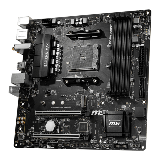
  • Seite 52: Übersicht Der Komponenten

    Übersicht der Komponenten SYS_FAN1 DIMMA1 DIMMA2 CPU_FAN1 DIMMB1 DIMMB2 CPU Sockel CPU_PWR1 ATX_PWR1 SATA1 SATA2 PCI_E1 M2_1 PCI_E2 SATA▼3▲4 PCI_E3 JCI1 JBAT1 JFP2 JFP1 JAUD1 JUSB3 SYS_FAN2 JUSB2 JUSB1 JRGB1 JLPT1 JCOM1 JTPM1 Übersicht der Komponenten...
  • Seite 53: Prozessorsockel

    Sie jedoch bitte sicher, dass die betroffenen Komponenten mit den abweichenden Einstellungen während des Übertaktens zurecht kommen. Von jedem Versuch des Betriebes außerhalb der Produktspezifikationen kann nur abgeraten werden. MSI übernehmt keinerlei Garantie für die Schäden und Risiken, die aus einem unzulässigem Betrieb oder einem Betrieb außerhalb der Produktspezifikation resultieren.
  • Seite 54: Dimm Steckplätze

    CPU und den installierten Geräten. Speichermodule können auf Basis der offizielle Spezifikation der AM4 CPU/ Speicher-Controller mit einer niedrigeren Frequenz unter dem Standardzustand arbeiten. Weitere Informationen zu kompatiblen Speichermodulen finden Sie unter: http://www.msi.com. Übersicht der Komponenten...
  • Seite 55: Pci_E1~3: Pcie Erweiterungssteckplätze

    PCI_E1~3: PCIe Erweiterungssteckplätze PCI_E1: PCIe 3.0 x16*/ PCIe 3.0 x8** PCI_E2: PCIe 2.0 x1 PCI_E3: PCIe 2.0 x1 * Für Ryzen 1. und 2. Generation Prozessoren ™ ** Für Ryzen mit Radeon Vega Grafikprozessoren ™ Wichtig Wenn Sie eine große und schwere Grafikkarte einbauen, benötigen Sie einen Grafikkarten-Stabilisator (Graphics Card Bolster) der das Gewicht trägt und eine Verformung des Steckplatzes vermeidet.
  • Seite 56: M2_1: M.2 Steckplatz (Key M)

    M2_1: M.2 Steckplatz (Key M) Video-Demonstration Eine anschauliche Darstellung zur Installation eines M.2 Moduls finden Sie im Video. http://youtu.be/JCTFABytrYA Installation einer M.2 SSD 1. Lösen Sie die M.2-Schraube aus dem 4. Schrauben Sie die M.2-SSD mit Motherboard. der mitgelieferten M.2-Schraube fest.
  • Seite 57: Jfp1, Jfp2: Frontpanel-Anschlüsse

    JFP1, JFP2: Frontpanel-Anschlüsse Diese Anschlüsse verbinden die Schalter und LEDs des Frontpanels. Power LED Power Switch JFP1 Reserved HDD LED Reset Switch HDD LED + Power LED + HDD LED - Power LED - Reset Switch Power Switch Reset Switch Power Switch Reserved No Pin...
  • Seite 58: Cpu_Pwr1, Atx_Pwr1: Stromanschlüsse

    CPU_PWR1, ATX_PWR1: Stromanschlüsse Mit diesen Anschlüssen verbinden Sie die ATX Stromstecker. CPU_PWR1 Ground +12V Ground +12V Ground +12V Ground +12V +3.3V +3.3V +3.3V -12V Ground Ground PS-ON# Ground Ground Ground ATX_PWR1 Ground Ground PWR OK 5VSB +12V +12V +3.3V Ground Wichtig Stellen Sie sicher, dass alle Anschlüsse mit den richtigen Anschlüssen des Netzteils verbunden sind, um einen stabilen Betrieb der Hauptplatine sicherzustellen.
  • Seite 59: Jusb1~2: Usb 2.0 Anschlüsse

    Bitte beachten Sie, dass Sie die mit VCC (Stromführende Leitung) und Ground (Erdleitung) bezeichneten Pins korrekt verbinden müssen, ansonsten kann es zu Schäden kommen. Um ein iPad, iPhone und einen iPod über USB-Anschlüsse aufzuladen, installieren Sie bitte die MSI SUPER CHARGER Software. ® JUSB3: USB 3.1 Gen1 Anschluss Mit diesem Anschluss können Sie den USB 3.1 Gen1 Anschluss auf dem Frontpanel...
  • Seite 60: Cpu_Fan1, Sys_Fan1~2: Stromanschlüsse Für Lüfter

    CPU_FAN1, SYS_FAN1~2: Stromanschlüsse für Lüfter Diese Anschlüsse können im PWM (Pulse Width Modulation) Modus oder Spannungsmodus betrieben werden. Im PWM-Modus bieten die Lüfteranschlüsse konstante 12V Ausgang und regeln die Lüftergeschwindigkeit per Drehzahlsteuersignal. Im DC-Modus bestimmen die Lüfteranschlüsse die Lüftergeschwindigkeit durch Ändern der Spannung. Wenn Sie ein 3-Pin (Non-PWM) Lüfter an einen PWM-Modus Lüfteranschluss anschließen, läuft der Lüfter mit höchster Drehzahl und kann unangenehm laut werden.
  • Seite 61: Jci1: Gehäusekontaktanschluss

    JCI1: Gehäusekontaktanschluss Dieser Anschluss wird mit einem Kontaktschalter verbunden. Normal Löse den (Standardwert) Gehäuseeingriff aus Gehäusekontakt-Detektor verwenden 1. Schließen Sie den JCI1-Anschluss am Gehäusekontakt-Schalter/ Sensor am Gehäuse an. 2. Schließen Sie die Gehäuseabdeckung. 3. Gehen Sie zu BIOS > SETTINGS > Security > Chassis Intrusion Configuration. 4.
  • Seite 62: Jbat1: Clear Cmos Steckbrücke (Reset Bios)

    (12V/G/R/B) mit der maximalen Leistung von 3 A (12 V). Schalten Sie die Stromversorgung aus und ziehen Sie das Netzkabel ab, bevor Sie die RGB-LED-Streifen ein- und ausbauen. Bitte verwenden Sie die MSI-Software zur Steuerung des LED-Leuchtstreifens. Übersicht der Komponenten...
  • Seite 63: Gpu Led

    GPU LED Diese LED zeigt an, dass die iGPU der CPU nicht erkannt wird und eine Grafikkarte installiert werden müssen. EZ Debug LEDs Diese LEDs zeigen den Status der Hauptkomponenten während des Boot-Vorgangs an Im Falle eines Fehlers, leuchtet die entsprechende LED bis zur Lösung des Problems vorübergehend dauerhaft.
  • Seite 64: Bios-Setup

    BIOS-Setup Die Standardeinstellungen bieten die optimale Leistung für die Systemstabilität unter Normalbedingungen. Sie sollten immer die Standardeinstellungen behalten, um mögliche Schäden des Systems oder Boot-Fehler zu vermeiden, außer Sie besitzen ausreichende BIOS Kenntnisse. Wichtig BIOS Funktionen werden für eine bessere Systemleistung kontinuierlich aktualisiert. Deswegen können die Beschreibungen leicht von der letzten Fassung des BIOS abweichen und sollten demnach nur als Anhaltspunkte dienen.
  • Seite 65: Reset Des Bios

    Before updating: Vorbereitung: Laden Sie bitte die neueste BIOS Version, die dem Motherboard-Modell entspricht, von der offiziellen MSI Website herunter und speichern Sie die BIOS-Datei auf USB-Flash- Laufwerk. BIOS-Aktualisierungsschritte: 1. Drücken Sie während des POST-Vorgangs die Taste (Entf), um das BIOS zu öffnen.
  • Seite 66: Ez Modus

    EZ Modus Im EZ-Modus können Sie die Grundinformationen des Systems einsehen und grundlegende Einstellungen konfigurieren. Um sich die erweiterten BIOS- Einstellungen anzeigen zu lassen, aktivieren Sie bitte den Erweiterten Modus durch Drücken des Setup Modus Schalter oder der Funktionstaste F7. Screenshot A-XMP Schalter Setup Modus Schalter...
  • Seite 67 y Boot-Geräte Prioritätsleiste - Sie können die Gerätesymbole verschieben, um die Startreihenfolge zu ändern. Die Bootreihenfolge sind mit “hoch” (links) bis “niedrig” (rechts) bezeichnet. y Informationsanzeige - Klicken Sie auf die Schaltfläche CPU, Memory, Storage, Fan Info und Help auf der linken Seite, um die jeweiligen Informationen anzuzeigen. y Funktionstasten - Aktivieren oder deaktivieren Sie LAN Option ROM, HD Audio Controller, AHCI/RAID, CPU Fan Fail Warning Control, Windows 10 WHQL support und BIOS Log Review durch Anklicken der zugehörigen Schaltfläche.
  • Seite 68: Erweiterter Modus

    Erweiterter Modus Drücken Sie den Setup Modus Schalter oder die Funkionstaste F7, um zwischen dem EZ-Modus und Erweiterten-Modus im BIOS-Setup zu wechseln. Screenshot A-XMP Schalter Setup Modus Schalter Suchen Sprache System- information GAME BOOST Schalter Bootgeräte- Prioritätsleiste BIOS-Menü BIOS-Menü -Auswahl -Auswahl Menüanzeige y GAME BOOST Schalter/ Setup Modus Schalter/ Screenshot/ Sprache/...
  • Seite 69: Oc Menü

    OC Menü In diesem Menü können Benutzer das BIOS anpassen und das Mainboard übertakten. Bitte führen Sie nur Änderungen durch, wenn Sie sich über das Ergebnis im Klaren sind. Sie sollten Erfahrung beim Übertakten haben, da Sie sonst das Motherboard oder Komponenten des Systems beschädigen können.
  • Seite 70 f A-XMP [Disabled] Aktivieren Sie die A-XMP Funktion oder wählen Sie ein Profil des Speichermoduls aus, um den Speicher zu übertakten. Diese Option erscheint nur, wenn die installierten Speichermodule/ das installierte Motherboard diese Funktion unterstützen. f DRAM Frequency [Auto] Setzen Sie die DRAM Frequenz. Bitte beachten Sie, dass ein zuverlässiges Übertaktungsverhalten nicht garantiert werden kann.
  • Seite 71 fCPU Technology Support Drücken Sie die Eingabetaste <Enter>, um das Untermenü aufzurufen. Das Untermenü zeigt die wichtigsten Eigenschaften der installierten CPU an. f MEMORY-Z Drücken Sie die Eingabetaste <Enter>, um das Untermenü aufzurufen. Dieses Untermenü zeigt alle Einstellungen und Timings des installierten Speichers. Zu diesen Informationen gelangen Sie auch, indem Sie die Taste [F5] drücken.
  • Seite 72 fRelaxed EDC throttling [Auto] (optional) Relaxed EDC throttling reduziert die Zeit, in der der Prozessor gedrosselt wird. the cores. [Auto] Empfehlung von AMD [Enabled] Reduziert die Zeit, in der der Prozessor gedrosselt wird. [Disabled] Der spezifische EDC-Drosselschutz ist aktiviert. fAMD Cool’ n’ Quiet [Enabled] Die Cool’...
  • Seite 73: Softwarebeschreibung

    Softwarebeschreibung Laden Sie die neuesten Treiber und Dienstprogramme von www.msi.com herunter und aktualisieren Sie sie. Installation von Windows ® 1. Schalten Sie den Computer ein. 2. Legen Sie die Windows 10 Disk in das optisches Laufwerk. ® 3. Drücken Sie die Taste Restart auf dem Computergehäuse.
  • Seite 75 Table des matières Informations de sécurité ..................2 Spécifications ......................3 Contenu ........................7 Panneau arrière Entrée/ Sortie ................8 Tableau explicatif de l’ état de la LED du port LAN ..........8 Realtek Audio Console ................... 8 Vue d’ ensemble des composants ............... 10 Socket processeur ....................
  • Seite 76: Informations De Sécurité

    Informations de sécurité y Les composants dans l’ emballage peuvent être endommagés par des décharges électrostatiques (ESD). Pour vous assurer de correctement monter votre ordinateur, veuillez vous référer aux instructions ci-dessous. y Assurez-vous de bien connecter tous les composants. En cas de mauvaise connexion, il se peut que l’...
  • Seite 77: Spécifications

    Architecture mémoire double canal y Support mémoire non-ECC UDIMM y Support mémoire ECC UDIMM (mode non-ECC) * Veuillez vous référer au site www.msi.com pour plus d’informations sur la mémoire compatible. y 1 x slot PCIe 3.0 x16 (PCI_E1) ƒ La vitesse x16 est supportée avec les processeurs Ryzen™...
  • Seite 78 Suite du tableau de la page précédente y Chipset AMD B450 ® ƒ 2 x ports USB 3.1 Gen1 (SuperSpeed USB) Type-A disponibles par l’ intermédiaire du connecteur USB 3.1 Gen1 interne ƒ 8 x ports USB 2.0 (High-speed USB) (4 ports Type-A sur le panneau arrière, 4 ports disponibles par l’...
  • Seite 79 Suite du tableau de la page précédente y 1 x connecteur d’ alimentation principal ATX 24 broches y 1 x connecteur d’ alimentation ATX 12V 8 broches y 4 x connecteurs SATA 6 Gb/s y 2 x connecteurs USB 2.0 (support de 4 autres ports USB 2.0) y 1 x connecteur USB 3.1 Gen1 (support de 2 autres ports USB 3.1 Gen1)
  • Seite 80 SMART TOOL y RAMDISK Logiciel y X-BOOST y GAMING APP y MYSTIC LIGHT y Open Broadcaster Software (OBS) y CPU-Z MSI GAMING y Norton Internet Security Solution ™ y Google Chrome , Google Toolbar et Google Drive ™ y Audio ƒ...
  • Seite 81: Contenu

    Suite du tableau de la page précédente y Performance ƒ DDR4 Boost ƒ GAME Boost ƒ CORE Boost y VR ƒ VR Ready Fonctions spéciales y Expérience des joueurs ƒ GAMING HOTKEY ƒ Contrôle de la souris GAMING y BIOS ƒ...
  • Seite 82: Panneau Arrière Entrée/ Sortie

    Panneau arrière Entrée/ Sortie Entrée Ligne USB 2.0 Type-A PS/2 USB 3.1 Gen1 Type-A Sortie Ligne DVI-D Entrée Microphone USB 2.0 Type-A USB 3.1 Gen1 Type-A Tableau explicatif de l’ état de la LED du port LAN LED indiquant la connexion LED indiquant la vitesse et l’...
  • Seite 83 y Sélection du périphérique - vous permet de sélectionner une source de sortie audio pour en modifier les paramètres. Le symbole de coche indique le périphérique sélectionné par défaut. y Amélioration d’ application - les diverses options vous fournissent un guide complet des effets acoustiques proposés pour les périphériques de sortie et d’...
  • Seite 84: Vue D' Ensemble Des Composants

    Vue d’ ensemble des composants SYS_FAN1 DIMMA1 DIMMA2 CPU_FAN1 DIMMB1 Socket DIMMB2 processeur CPU_PWR1 ATX_PWR1 SATA1 SATA2 PCI_E1 M2_1 SATA▼3▲4 PCI_E2 PCI_E3 JCI1 JBAT1 JFP2 JFP1 JAUD1 JUSB3 SYS_FAN2 JUSB2 JUSB1 JRGB1 JLPT1 JCOM1 JTPM1 Vue d’ ensemble des composants...
  • Seite 85: Socket Processeur

    Cette carte mère supporte l’ overclocking. Néanmoins, veuillez vous assurer que vos composants soient capables de tolérer l’ overclocking. Prenez note que l’ utilisation au-delà des spécifications du constructeur n’ est pas recommandée. MSI ne garantit ®...
  • Seite 86: Slots Dimm

    Du fait des limites officiels des spécifications du contrôleur CPU/ mémoire AM4, les modules de mémoire peuvent fonctionner à une fréquence réduite par rapport à la valeur indiquée en mode défaut. Veuillez vous référer au site www.msi.com pour plus d’ informations sur la mémoire compatible.
  • Seite 87: Pci_E1~3 : Slots D' Extension Pcie

    Important Si vous installez une carte graphique lourde, il vous faut utiliser un outil comme la barre de support MSI Gaming Series pour supporter son poids et pour éviter la déformation du slot. Veillez à toujours mettre l’ ordinateur hors tension et à débrancher le cordon d’...
  • Seite 88: M2_1 : Slot M.2 (Touche M)

    M2_1 : Slot M.2 (Touche M) Vidéo de démonstration Référez-vous à la vidéo d’ instruction sur l’ installation du module M.2. http://youtu.be/JCTFABytrYA Installation du SSD M.2 1. Desserrez la vis M.2 de la carte mère. 3. Insérez votre SSD M.2 dans le slot M.2 à...
  • Seite 89: Jfp1, Jfp2 : Connecteurs De Panneau Avant

    JFP1, JFP2 : Connecteurs de panneau avant Ces connecteurs se lient aux interrupteurs et indicateurs LED du panneau avant. Power LED Power Switch JFP1 Reserved HDD LED Reset Switch HDD LED + Power LED + HDD LED - Power LED - Reset Switch Power Switch Reset Switch...
  • Seite 90: Cpu_Pwr1, Atx_Pwr1 : Connecteurs D' Alimentation

    CPU_PWR1, ATX_PWR1 : Connecteurs d’ alimentation Ces connecteurs vous permettent de relier une alimentation ATX. CPU_PWR1 Ground +12V Ground +12V Ground +12V Ground +12V +3.3V +3.3V +3.3V -12V Ground Ground PS-ON# Ground Ground Ground ATX_PWR1 Ground Ground PWR OK 5VSB +12V +12V +3.3V...
  • Seite 91: Jusb1~2 : Connecteurs Usb 2.0

    Notez que les broches VCC et Terre doivent être branchées correctement afin d’ éviter tout dommage sur la carte mère. Pour recharger votre iPad, iPhone et iPod par l’ intermédiaire d’ un port USB, veuillez installer l’ utilitaire MSI SUPER CHARGER. ®...
  • Seite 92: Cpu_Fan1, Sys_Fan1~2 : Connecteurs Pour Ventilateurs

    CPU_FAN1, SYS_FAN1~2 : Connecteurs pour ventilateurs Les connecteurs pour ventilateurs peuvent être utilisés en mode PWM (Pulse Width Modulation) et en mode DC. En mode PWM, les connecteurs fournissent une sortie de 12V constante et ajustent la vitesse des ventilateurs avec un signal de contrôle de vitesse.
  • Seite 93: Jci1 : Connecteur Intrusion Châssis

    JCI1 : Connecteur intrusion châssis Ce connecteur est relié à un câble d’ interrupteur intrusion châssis. Normal Commencer l’ activité intrusion châssis (défaut) Utilisation du détecteur d’ intrusion châssis 1. Reliez le connecteur JCI1 à l’ interrupteur ou au capteur d’ intrusion châssis situé sur le boîtier du PC.
  • Seite 94: Jbat1 : Cavalier Clear Cmos (Réinitialisation Bios)

    Avant d’ installer ou de retirer le ruban LED RGB, veillez à toujours éteindre l’ alimentation et à débrancher le câble d’ alimentation de la prise électrique. Veuillez utiliser un logiciel MSI dédié pour contrôler le ruban d’ extension LED. Vue d’ ensemble des composants...
  • Seite 95: Indicateur Led Du Gpu

    Indicateur LED du GPU Cette LED indique que la puce graphique iGPU du CPU n’ est pas détectée et qu’ il faut installer une carte graphique. EZ Debug LEDs Ces LED indiquent l’ état des composants clés au cours du processus de démarrage. En cas d’...
  • Seite 96: Configuration Du Bios

    Configuration du BIOS Les réglages par défaut fournissent une performance optimale pour la stabilité du système en conditions normales. Veillez à toujours garder les réglages par défaut pour éviter d’ endommager le système ou tout problème au démarrage, sauf si vous êtes familier avec le BIOS.
  • Seite 97: Réinitialiser Le Bios

    Avant la mise à jour : Veuillez télécharger la dernière version de BIOS compatible à votre carte mère sur le site MSI. Ensuite, veuillez sauvegarder le nouveau BIOS sur le lecteur flash USB. Mettre le BIOS à jour : 1. Appuyez sur la touche Suppr pour entrer dans l’ interface Setup du BIOS pendant le processus de POST.
  • Seite 98: Ez Mode (Mode Simplifié)

    EZ Mode (mode simplifié) Le mode EZ vous fournit les informations basiques du système et vous permet de configurer les réglages de base. Si vous souhaitez configurer les réglages du BIOS, veuillez utiliser le mode Advanced en appuyant sur le switch Setup Mode (Interrupteur de modes de réglages) ou la touche de fonction F7.
  • Seite 99 y Langue - vous permet de choisir la langue du BIOS. y Informations du système - montre la vitesse et la tension du processeur et de la mémoire, la température du processeur et de la carte mère, le type de carte mère et de processeur, la capacité...
  • Seite 100: Advanced Mode (Mode Avancé)

    Advanced Mode (mode avancé) Appuyez sur le Setup Mode switch (interrupteur de modes de réglages) ou sur la touche de fonction F7 pour commuter entre le mode simplifié et le mode avancé. Interrupteur de Capture d’ écran Interrupteur A-XMP modes de réglages Recherche Langue Information...
  • Seite 101: Oc Menu (Menu Overclocking)

    OC Menu (menu overclocking) Ce menu est destiné aux utilisateurs avancés souhaitant overclocker leur carte mère. Important L’ overclocking manuel du PC n’ est recommandé que pour les utilisateurs avancés. L’ overclocking n’ est pas garanti et une mauvaise manipulation peut rendre nulle votre garantie et sévèrement endommager votre matériel.
  • Seite 102 f DRAM Frequency [Auto] Définit la fréquence de la mémoire. Veuillez noter que les résultats de l’ overclocking ne sont pas garantis. f Adjusted DRAM Frequency Affiche la fréquence ajustée de la mémoire. Fonctionne en lecture seule. f Memory Try It ! [Disabled] Memory Try It! permet d’...
  • Seite 103 f MEMORY-Z Appuyez sur la touche Entrée pour accéder au sous-menu. Ce sous-menu affiche tous les réglages et timings de la mémoire installée. Vous pouvez également accéder à ce sous-menu à tout moment en appuyant sur la touche [F5]. fDIMMx Memory SPD Appuyez sur la touche Entrée pour accéder au sous-menu.
  • Seite 104 fRelaxed EDC throttling [Auto] (en option) Relaxed EDC throttling réduit le laps de temps pendant lequel le processeur réduira la consommation des coeurs. [Auto] Recommandation d’ AMD. [Enabled] Réduire le laps de temps pendant lequel le processeur réduira sa consommation. [Disabled] Activer la fonction de protection EDC throttling des parties spécifiques.
  • Seite 105: Informations Sur Les Logiciels

    Informations sur les logiciels Veuillez vous référer au site www.msi.com pour télécharger et mettre à jour les derniers utilitaires et pilotes. Installer Windows ® 1. Allumez l’ ordinateur. 2. Insérez le disque de Windows 10 dans le lecteur optique. ®...
  • Seite 107 Содержание Безопасное использование продукции ............2 Технические характеристики ................ 3 Комплект поставки ................... 7 Задняя панель портов ввода/ вывода ............8 Таблица состояний индикатора порта LAN ........... 8 Realtek Audio Console ................... 8 Компоненты материнской платы ............... 10 Процессорный сокет ..................11 Слоты...
  • Seite 108: Безопасное Использование Продукции

    Безопасное использование продукции y Компоненты, входящие в комплект поставки могут быть повреждены статическим электричеством. Для успешной сборки компьютера, пожалуйста, следуйте указаниям ниже. y Убедитесь, что все компоненты компьютера подключены должным образом. Ослабленные соединения компонентов могут привести как к сбоям в работе, так и полной неработоспособности компьютера. y Чтобы...
  • Seite 109: Технические Характеристики

    Двухканальная архитектура памяти y Поддержка памяти non-ECC UDIMM y Поддержка памяти ECC UDIMM (в режиме non-ECC) * Пожалуйста, обратитесь www.msi.com для получения дополнительной информации о совместимой памяти. y 1x слот PCIe 3.0 x16 (PCI_E1) ƒ Поддержка режима x16 с процессорами AMD ®...
  • Seite 110: Разъемы Задней Панели

    Продолжение с предыдущей страницы y Контроллер AMD B450 ® ƒ 2x порта USB 3.1 Gen1 (SuperSpeed USB) Type-A доступны через внутренние разъемы USB 3.1 Gen1 ƒ 8x портов USB 2.0 (High-speed USB) (4 порта Type-A на задней панели, 4 порта доступны через внутренние...
  • Seite 111 Продолжение с предыдущей страницы y 1x 24-контактный разъем питания ATX y 1x 8-контактный разъем питания ATX 12В y 4x разъема SATA 6Гб/с y 2x разъема USB 2.0 (поддержка 4-х дополнительных портов USB 2.0) y 1x разъем USB 3.1 Gen1 (поддержка 2-х дополнительных...
  • Seite 112: Программное Обеспечение

    RAMDISK обеспечение y X-BOOST y GAMING APP y MYSTIC LIGHT y Open Broadcaster Software (OBS) y CPU-Z MSI GAMING y Norton™ Internet Security Solution y Google Chrome™, Google Toolbar, Google Drive y Аудио ƒ Audio Boost y Накопитель ƒ Turbo M.2 ƒ...
  • Seite 113: Комплект Поставки

    Продолжение с предыдущей страницы y Производительность ƒ DDR4 Boost ƒ GAME Boost ƒ CORE Boost y VR ƒ VR Ready Эксклюзивные y Ощущение игроков функции ƒ GAMING HOTKEY ƒ GAMING MOUSE Control y BIOS ƒ Click BIOS 5 y Сертификация ƒ...
  • Seite 114: Задняя Панель Портов Ввода/ Вывода

    Задняя панель портов ввода/ вывода Линейный вход USB 2.0 Type-A PS/2 USB 3.1 Gen1 Type-A Линейный DVI-D выход Микрофонный вход USB 2.0 Type-A USB 3.1 Gen1 Type-A Таблица состояний индикатора порта LAN Подключение/ Работа Скорость передачи данных индикатора Состояние Описание Состояние...
  • Seite 115 y Выбор устройства - позволяет выбрать источник аудио выхода и изменить соответствующие параметры. Отмеченное устройство будет использоваться по умолчанию. y Дополнительные эффекты - это список опций по настройке звуковых эффектов для входного и выходного сигнала аудио устройства. y Расширенные настройки - обеспечивают работу с двумя независимыми потоками...
  • Seite 116: Компоненты Материнской Платы

    Компоненты материнской платы SYS_FAN1 DIMMA1 DIMMA2 CPU_FAN1 DIMMB1 Процессорный DIMMB2 CPU_PWR1 сокет ATX_PWR1 SATA1 SATA2 PCI_E1 M2_1 SATA▼3▲4 PCI_E2 PCI_E3 JCI1 JBAT1 JFP2 JFP1 JAUD1 JUSB3 SYS_FAN2 JUSB2 JUSB1 JRGB1 JLPT1 JCOM1 JTPM1 Компоненты материнской платы...
  • Seite 117: Процессорный Сокет

    «разгона». Перед выполнением разгона системы убедитесь в том, что все компоненты системы смогут его выдержать. Производитель не рекомендует использовать параметры, выходящие за пределы технических характеристик устройств. Гарантия MSI не распространяется на повреждения и другие ® возможные последствия ненадлежащей эксплуатации оборудования.
  • Seite 118: Слоты Dimm

    разгоне зависит от установленного процессора и других устройств. Из-за ограничений официальной спецификации процессора АМ4/ контроллера памяти, модули памяти могут работать на частотах ниже заявленной производителем при насройках по умолчанию. Дополнительную информацию о совместимых модулях памяти можно найти на веб-сайте www.msi.com. Компоненты материнской платы...
  • Seite 119: Pci_E1~3: Слоты Расширения Pcie

    ** Для процессоров Ryzen™ с видеокартами Radeon Vega Внимание! При установке массивной видеокарты, необходимо использовать такой инструмент, как MSI Gaming Series Graphics Card Bolster для поддержки веса графической карты и во избежание деформации слота. Перед установкой или извлечением плат расширения убедитесь, что кабель...
  • Seite 120: M2_1: Разъем M.2 (Ключ M)

    M2_1: Разъем M.2 (Ключ M) Видео Инструкция Смотрите видео, чтобы узнать как использовать модуль M.2. http://youtu.be/JCTFABytrYA Установка M.2 SSD 1. Выкрутите стойку для крепления 3. Вставьте M.2 SSD в разъем M.2 модуля из материнской платы. М.2 под углом 30 градусов. 2.
  • Seite 121: Jfp1, Jfp2: Разъемы Передней Панели

    JFP1, JFP2: Разъемы передней панели Эти разъемы служат для подключения кнопок и светодиодных индикаторов, расположенных на передней панели. Power LED Power Switch JFP1 Reserved HDD LED Reset Switch HDD LED + Power LED + HDD LED - Power LED - Reset Switch Power Switch Reset Switch...
  • Seite 122: Cpu_Pwr1, Atx_Pwr1: Разъемы Питания

    CPU_PWR1, ATX_PWR1: Разъемы питания Данные разъемы предназначены для подключения блока питания ATX. CPU_PWR1 Ground +12V Ground +12V Ground +12V Ground +12V +3.3V +3.3V +3.3V -12V Ground Ground PS-ON# Ground Ground Ground ATX_PWR1 Ground Ground PWR OK 5VSB +12V +12V +3.3V Ground Внимание! Для...
  • Seite 123: Jusb1~2: Разъемы Usb 2.0

    Внимание! Помните, что во избежание повреждений, необходимо правильно подключать контакты VCC и земли. Для того, чтобы зарядить ваш iPad, iPhone и iPod через порты USB, пожалуйста, установите утилиту MSI SUPER CHARGER. ® JUSB3: Разъем USB 3.1 Gen1 Данный разъем предназначен для подключения портов USB 3.1 Gen1 на...
  • Seite 124: Cpu_Fan1, Sys_Fan1~2: Разъемы Вентиляторов

    CPU_FAN1, SYS_FAN1~2: Разъемы вентиляторов Разъемы вентиляторов можно разделить на два типа: с PWM (PulseWidth Modulation) управлением и управлением постоянным током. Разъемы вентиляторов с PWM управлением имеют контакт с постоянным напряжением 12В, а также контакт с сигналом управления скоростью вращения. Управление скоростью...
  • Seite 125: Jci1: Разъем Датчика Открытия Корпуса

    JCI1: Разъем датчика открытия корпуса К этому разъему подключается кабель от датчика открытия корпуса. Разрешить запись Нормально по событию (По умолчанию) открытия корпуса Использование датчика открытия корпуса 1. Подключите датчик открытия корпуса к разъему JCI1. 2. Закройте крышку корпуса. 3. Войдите в BIOS > SETTINGS > Security > Chassis Intrusion Configuration. 4.
  • Seite 126: Jrgb1: Разъем Rgb Led

    Разъем JRGB1 поддерживает подключение 5050 RGB непрерывных светодиодных лент (12В/G/R/B) длиной до 2 метров с максимальной мощностью 3А (12В). Перед установкой или заменой светодиодных лент RGB, необходимо полностью обесточить систему и отключить кабель питания. Используйте утилиту MSI для управления удлинительными ® светодиодными лентами. Индикатор GPU Данный...
  • Seite 127: Настройка Bios

    Настройка BIOS Настройки по умолчанию обеспечивают оптимальную производительность и стабильность системы при нормальных условиях. Если вы недостаточно хорошо знакомы с BIOS, всегда устанавливайте настройки по умолчанию. Это позволит избежать возможных повреждений системы, а также проблем с загрузкой. Внимание! С целью улучшения производительности, меню BIOS постоянно обновляется.
  • Seite 128: Сброс Bios

    обратитесь к разделу “Джампер очистки данных CMOS” . Обновление BIOS Обновление BIOS при помощи M-FLASH Подготовительные операции: Пожалуйста, скачайте последнюю версию файла BIOS с сайта MSI, который соответствует вашей модели материнской платы. Сохраните файл BIOS на флэш-диске USB. Обновление BIOS: 1.
  • Seite 129: Режим Ez

    Режим EZ Режим EZ предоставляет основную информацию о системе и позволяет выполнить основные операции по настройке. Для настройки расширенных функций BIOS, пожалуйста, войдите в Расширенный режим, путем нажатия Переключатель режимов установки или при помощи функциональной клавиши F7. Переключатель Скриншот режимов установки Переключатель...
  • Seite 130 y Язык - позволяет выбрать язык интерфейса для настройки BIOS. y Информация о системе - показывает частоту процессора/ памяти, температуру процессора/ материнской платы, информацию о материнской плате/процессоре, размер памяти, напряжение на процессоре/ памяти, версию BIOS и дату создания. y Приоритет загрузочных устройств - вы можете переместить инонку устройства...
  • Seite 131: Режим Разгона

    Режим разгона Нажмите переключатель режимов установки или функциональную клавишу F7 для переключения между режимами EZ и разгона в настройках BIOS. Переключатель Скриншот режимов установки Поиск Переключатель A-XMP Язык Информация о системе Переключатель Приоритет GAME BOOST загрузочных устройств Выбор меню Выбор меню BIOS BIOS Экран...
  • Seite 132: Меню Oc

    Меню OC Данное меню предназначено для опытных пользователей и предоставляет возможности для «разгона» системы. Внимание! Разгонять ПК вручную рекомендуется только опытным пользователям. Производитель не гарантирует успешность разгона. Неправильное выполнение разгона может привести к аннулированию гарантии и серьезному повреждению оборудования. Неопытным пользователям рекомендуется использовать функцию GAME BOOST.
  • Seite 133 f DRAM Frequency [Auto] Установка частоты памяти DRAM. Обратите внимание, что возможность успешного разгона не гарантируется. f Adjusted DRAM Frequency Показывает текущую частоту процессора. Это значение нельзя изменять. f Memory Try It ! [Disabled] Позволяет улучшить совместимость памяти и производительность, путем выбора...
  • Seite 134 f MEMORY-Z Нажмите Enter для входа в подменю. В подменю выделены все параметры и тайминги установленной памяти. Для просмотра этой информации в любое время нажмите на кнопку [F5]. fDIMMx Memory SPD Нажмите Enter для входа в подменю. Это подменю показывает информацию...
  • Seite 135 fRelaxed EDC throttling [Auto] (опционально) Relaxed EDC throttling уменьшает время троттлинга ядера процессора. Рекомендовано AMD [Auto] Уменьшает время троттлинга процессора. [Enabled] Включает специальную частичную защиту EDC троттлинга. [Disabled] fAMD Cool’ n’ Quiet [Enabled] Технология Cool ’ n ’ Quiet позволяет эффективно динамически изменять частоту...
  • Seite 136: Описание Программного Обеспечения

    Описание программного обеспечения Скачайте и обновите последние утилиты и драйверы с сайта: www.msi.com Установка Windows ® 1. Включите компьютер. 2. Вставьте диск Windows 10 в привод для оптических дисков. ® 3. Нажмите кнопку Restart на корпусе компьютера. 4. Нажмите клавишу F11 во время POST (Power-On Self Test) компьютера, чтобы...
  • Seite 137: Regulatory Notices

    The point of contact for regulatory matters is MSI, recycling and disposing of their end-of-life products. MSI-NL Eindhoven 5706 5692 ER Son. y Visit the MSI website and locate a nearby distributor B급 기기 (가정용 방송통신기자재) for further recycling information.
  • Seite 138 MSI will comply with the product take entregar a una empresa autorizada para la recogida de back requirements at the end of life of MSI-branded estos residuos.
  • Seite 139 MSI si adeguerà a tale Direttiva ritirando tutti i prodotti marchiati MSI che sono stati venduti all’interno dell’Unione Europea alla fine del loro ciclo di vita.
  • Seite 140 Micro-Star Int’ l Co., Ltd. All other marks and names mentioned may be trademarks of their respective owners. No warranty as to accuracy or completeness is expressed or implied. MSI reserves the right to make changes to this document without prior notice. Technical Support...

Inhaltsverzeichnis