thyracont VSP63MA4 Betriebsanleitung
Vakuum transmitter

Verwandte Anleitungen für thyracont VSP63MA4


Inhaltszusammenfassung für thyracont VSP63MA4
- Seite 1 V a c u u m I n s t r u m e n t s VSP63MA4, VCP63MA4 Vakuum Transmitter Vacuum Transducer Betriebsanleitung Operating Instructions...
-
Seite 3: Inhaltsverzeichnis
3.3 Elektrischer Anschluss ......3.3.1 Anschluss an Thyracont Anzeigegeräte ... . -
Seite 4: Hinweise Für Ihre Sicherheit
1 Hinweise für Ihre Sicherheit Lesen und befolgen Sie alle Punkte dieser Anleitung Informieren Sie sich über Gefahren, die vom Gerät ausgehen und Gefahren, die von Ihrer Anlage ausgehen Beachten Sie die Sicherheits- und Unfall-Verhütungsvorschriften Prüfen Sie regelmäßig die Einhaltung aller Schutzmaßnahmen Installieren Sie das VSP/VCP unter Einhaltung der entsprechenden Umgebungsbe- dingungen;... -
Seite 5: Vakuum Transmitter Vsp/Vcp
2 Vakuum Transmitter VSP/VCP 2.1 Zur Orientierung Diese Betriebsanleitung ist gültig für Produkte mit den Artikelnummern VSP63MA4, VCP63MA4. Sie finden die Artikelnummern auf dem Typenschild. Technische Änderungen oh- ne vorherige Anzeige sind vorbehalten. 2.2 Lieferumfang Zum Lieferumfang gehören: Transmitter VSP/VCP... -
Seite 6: Produktbeschreibung
- 1000 mbar. Der Transmittertyp VCP mit Pt/Rh Fi- lament ist für den Einsatz in vielen Korrosivgas-Anwendungen geeignet und misst Absolutdruck im Bereich 5,0x10 - 1000 mbar. Das Gerät kann an ein Thyracont Anzeigegerät angeschlossen oder gemäß Anschlussbelegung mit einer kundenei- genen Spannungsversorgung betrieben werden. -
Seite 7: Installation
3 Installation 3.1 Hinweise zur Installation Keine eigenmächtigen Umbauten oder Veränderungen am Gerät vornehmen! Aufstellungsort: Innenräume Für nicht vollklimatisierte Betriebsräume gilt: Temperatur: +5 C ... +60 C Rel. Luftfeuchte: max. 80% bis 30 C, max. 50% bei 40 C, nicht betauend Luftdruck: 860 - 1060 hPa (mbar) 3.2 Vakuumanschluss Schmutz und Beschädigungen, insbesondere am Flansch, beein-... -
Seite 8: Elektrischer Anschluss
Druck nicht mehr standhalten. Dies kann zu Gesundheitsschäden durch ausströmende Prozessmedien führen! 3.3 Elektrischer Anschluss 3.3.1 Anschluss an Thyracont Anzeigegeräte Wird der Transmitter an einem Thyracont Anzeigegerät betrieben, ist ein geeigne- tes Messkabel zu verwenden (siehe Zubehör). Anschluss des Transmitters niemals mit Spannung führendem Ka- bel herstellen! Stecker am Transmitter einstecken und mit Schrauben sichern. -
Seite 9: Kundeneigene Spannungsversorgung
3.3.2 Kundeneigene Spannungsversorgung Der Transmitter kann auch mit anderen Anzeigegeräten oder kundeneigener Span- nungsversorgung betrieben werden. Die elektrische Verbindung ist unter Verwendung geeigneter Kabel EMV-gerecht gemäß untenstehender Pinbelegung herzustellen: Stecker M12, A-kodiert, 5polig, männlich Pin1: Signal Output 4-20 mA Pin2: Do not connect Pin3: Voltage Supply 15...30 VDC... -
Seite 10: Betrieb
4 Betrieb 4.1 Allgemeines Messprinzip Vakuum Transmitter des Typs VSP und VCP besitzen einen Piranisensor, der die Wärmeleitfähigkeit von Gasen zur Vakuummessung nutzt. Dabei wird ein Wendel-Filament im Pulsbetrieb bis zu einem bestimmten Tempe- raturschwellwert aufgeheizt. Die notwendige Aufheizzeit ist ein Maß für den Abso- lutdruck. -
Seite 11: Nachjustieren
4.2 Nachjustieren Das Gerät ist ab Werk bei Versorgungsspannung 24 V stehend, d.h. mit dem Flansch nach unten, abgeglichen. Andere Einbaulagen, Einsatz unter anderen kli- matischen Bedingungen, extreme Temperaturschwankungen, Alterung oder Ver- schmutzung können ein Nachjustieren erforderlich machen. Um optimale Ergebnisse beim Nachjustieren zu erzielen, empfeh- len wir vor jedem Abgleich eine Warmlaufphase von mindestens 15 Minuten beim jeweiligen Kalibrierdruck zu beachten. - Seite 12 Abgleich auf einen benutzerdefinierten Nulldruck-Referenzwert Der Pirani-Sensor kann auch auf einen beliebigen Referenzdruck kleiner 1,0x10 mbar abgeglichen werden. Dazu zunächst die Gummistopfen über beiden Tastern entfernen (1), dann mit einem dünnen Schraubendreher oder ähnlichem Hilfsmittel kurz auf den Taster »Set« drücken (2). Am Signalausgang wird nun für 5 s ein Wert ausgegeben, der dem momentan eingestellten Nullpunkt-Justierwert entspricht (Werkseinstellung: Ausgabewert für »ur«...
-
Seite 13: Wartung Und Service
5 Wartung und Service Vorsicht bei kontaminierten Teilen! Es kann zu Gesundheitsschäden kommen. Informieren Sie sich vor Aufnahme der Arbeiten über eine eventuelle Kontamination. Be- achten Sie beim Umgang mit kontaminierten Teilen die einschlägi- gen Vorschriften und Schutzmaßnahmen. Das Gerät ist wartungsfrei. Äußerliche Verschmutzungen können mit einem feuch- ten Tuch beseitigt werden. - Seite 14 VSP/VCP-4-20 mA-201126...
-
Seite 15: Technische Daten
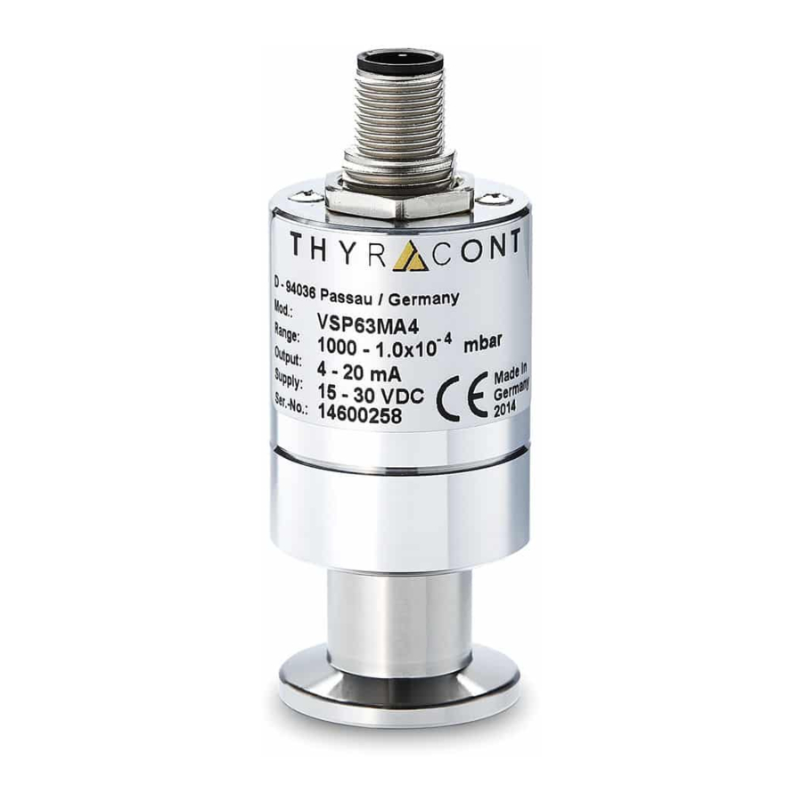
6 Technische Daten Messprinzip Wärmeleitfähigkeit Impuls-Pirani, gasartabhängig Messbereich VSP: 1000 - 1,0x10 mbar (750 - 1,0x10 Torr) VCP: 1000 - 5,0x10 mbar (750 - 5,0x10 Torr) Max. Überlast 10 bar abs. Genauigkeit VSP: 1000 ... 20 mbar: ca. 30% v. Messwert 20 ... - Seite 16 Ausgangssignal 4 - 20 mA, logarithmisch Elektrischer Anschluss M12 Rundsteckverbinder A-codiert, 5polig, männl., verschraubbar Vakuumanschluss VSP63, VCP63: Kleinflansch DN16 ISO KF Schutzart IP 54 Gewicht ca. 100 g (VSP63) VSP/VCP-4-20 mA-201126...
-
Seite 17: Konformitätserklärung
7 Konformitätserklärung VSP/VCP-4-20 mA-201126... - Seite 18 VSP/VCP-4-20 mA-201126...
-
Seite 33: Declaration Of Conformity
7 Declaration of Conformity VSP/VCP-4-20 mA-201126... - Seite 34 VSP/VCP-4-20 mA-201126...
- Seite 35 VSP/VCP-4-20 mA-201126...
- Seite 36 VSP/VCP-4-20 mA-201126...