Werbung
Quicklinks
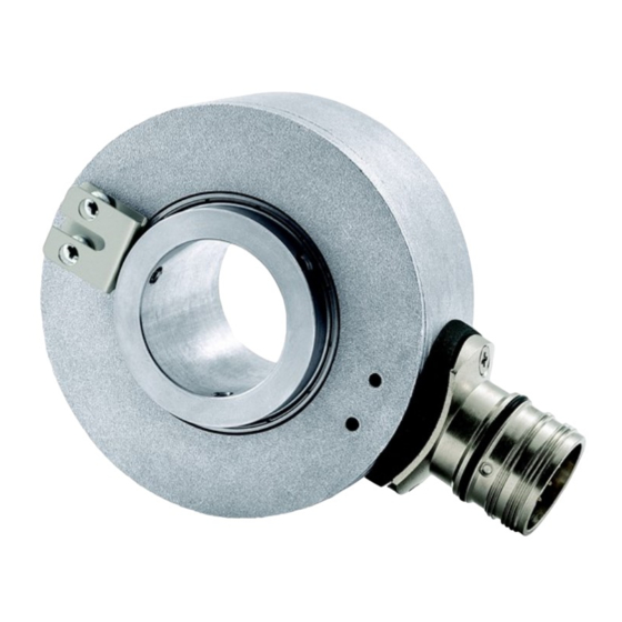
ROTAPULS
Incremental encoders
Series
More info at www.lika.biz
Warning: encoders having order code ending with "/Sxxx" may have mechanical and electrical characteristics different from standard and be supplied with additional documentation for special connections (Technical Info).
Attenzione: gli encoder con codice di ordinazione finale "/Sxxx" possono avere caratteristiche meccaniche ed elettriche diverse dallo standard ed essere provvisti di documentazione aggiuntiva per cablaggi speciali (Technical info).
Achtung: Geräte, deren Bestellschlüssel mit der Kennung /Sxxx enden, können in ihren mech. und elektr. Eigenschaften vom Standard abweichen. Diese werden daher mit einer ergänzenden Dokumentation ausgeliefert (Technical info).
Atención: los encoders con código de pedido acabado en "/Sxxx" pueden tener características mecánicas y eléctricas diferentes a las básicas y documentación adicional relativa a conexiones especiales (Technical Info).
Attention: les codeurs avec code de commande terminant en "/Sxxx" peuvent avoir des caractéristiques mécaniques et électriques différentes du standard et documentation additionnelle pour les câblages spéciaux (Technical info).
EN
Mounting instructions
Insert the BR2 type reducing sleeve 1 (if supplied) into the encoder shaft
(fixing holes 2 have to match);
mount the encoder on the motor shaft;
make sure the anti-rotation pin 3 (tempered pin) is inserted properly into the
fixing plate 4;
fix the encoder shaft by tightening the three grub screws 2 (3 x M4).
ES
Instrucciones de montaje
Insertar el manguito reductor BR2 1 (si se suministra) en el eje del encoder
(los orificios de fijación 2 deben quedar alineados);
montar el encoder en el eje del motor;
asegurarse de que el pin antigiro 3 (pasador temprado) queda insertado en la
placa de fijación 4;
fijar el eje del encoder mediante los tres tornillos previstos 2 (3 x M4).
C80
C81 - C82
Signals
A
/A
Brown
AB0 outputs
Marrone
(5-wire I5 type
Braun
-
cable)
Marrón
Marron
EDE 9-pin
1
2
M23 12-pin
1
2
Yellow
Blue
AB0, /AB0
Giallo
Blu
outputs
Gelb
Blau
(8-wire I8 type
Amarillo
Azul
cable)
Jaune
Bleu
Installation has to be carried out with power supply disconnected.
L'installazione deve essere eseguita in assenza di tensione.
Der Anschluss darf nur bei ausgeschalteter Versorgungsspannung erfolgen.
La instalación sólo debe ser efectuada en ausencia total de tensión.
Le montage du dispositif doit être effectué en
C80 • C81 • C82
IT
Inserire la boccola di riduzione BR2 1 (se fornita) nell'albero encoder (i fori di
fissaggio 2 devono combaciare);
inserire l'encoder sull'albero del motore;
assicurarsi che il pin antirotazione 3 (spina temprata) sia inserito nella molla
di fissaggio 4;
fissare l'albero encoder tramite i tre grani 2 previsti sull'albero (3 x M4).
FR
Introduire la douille de réduction type BR2 1 (si fournie) à l'intérieur de
l'arbre codeur (les trous de fixation 2 doivent coïncider parfaitement);
monter le codeur sur l'arbre du moteur;
s'assurer que le pivot antirotation 3 (goupille durcie) soit inséré sur la
plaquette de fixation 4;
fixer le codeur au moyen des trois boulons sans tête 2 prévus au niveau de
l'arbre (3 x M4).
Electrical connections
B
/B
0
/0
Blue
White
Blu
Bianco
Blau
-
Weiß
-
Azul
Blanco
Bleu
Blanc
3
4
5
6
3
4
5
6
Green
Orange
White
Grey
Verde
Arancione
Bianco
Grigio
Grün
Orange
Weiß
Grau
Verde
Anaranjado
Blanco
Gris
Vert
Orange
Blanc
Gris
absence totale de tension.
Istruzioni di montaggio
Instructions de montage
Connector type
+Vdc
0Vdc
Shield
male frontal side
Red
Black
Shield
maschio lato contatti
Rosso
Nero
Schermo
Aufsicht Stiftseite
Rot
Schwarz
Schirm
macho lado contactos
Rojo
Negro
Malla
mâle côté contacts
Rouge
Noir
Blindage
8
9
Case
7
8
Case
Red
Black
Shield
Rosso
Nero
Schermo
Rot
Schwarz
Schirm
Rojo
Negro
Malla
Rouge
Noir
Blindage
DE
Montagehinweise
Reduzierhülse Typ BR2 1 (wenn erforderlich) in die Hohlwelle einsetzen. Die
Bohrungen für die Fixierschrauben 2 müssen übereinstimmen;
den Geber auf die Motorwelle montieren;
der (gehärtete) Stift 3 für die Verdrehsicherung muß korrekt in die
Verdrehstütze 4 eingreifen;
die Hohlwelle kann jetzt durch Anziehen der drei Gewindestifte 2 (3 x M4)
fixiert werden.
EDE 9-pin
Wires not used must be cut at different
lengths and insulated singularly
M23 12-pin
Werbung

Verwandte Anleitungen für Lika ROTAPULS C80 Serie


Inhaltszusammenfassung für Lika ROTAPULS C80 Serie
- Seite 1 C80 • C81 • C82 Series More info at www.lika.biz Warning: encoders having order code ending with "/Sxxx" may have mechanical and electrical characteristics different from standard and be supplied with additional documentation for special connections (Technical Info). Attenzione: gli encoder con codice di ordinazione finale “/Sxxx” possono avere caratteristiche meccaniche ed elettriche diverse dallo standard ed essere provvisti di documentazione aggiuntiva per cablaggi speciali (Technical info).
- Seite 2 Dispose separately Lika Electronic reserves the right to make changes in specifications without prior notice – Lika si riserva il diritto di apportare modifiche senza preavviso - Die Fa. Lika Electronic behält sich das Recht zu Änderungen ohne Vorankündigung vor - Informaciones pueden ser modificadas por Lika Electronic sin previo aviso – Les informations peuvent être modifiées par Lika Electronic sans avis préalable...