Werbung
Quicklinks
RT-A10f
Thermostat électronique pour la régulation de la température
Sicherheitshinweis!
Dieses Gerät darf nur durch eine Elektrofachkraft geöffnet und gemäß dem entsprechenden
Schaltbild im Gehäusedeckel / auf dem Gehäuse / in der Bedienungsanleitung installiert
werden. Dabei sind die bestehenden Sicherheitsvorschriften zu beachten. Nach der Instal-
lation ist der Betreiber, durch die ausführende Installationsfirma, in die Funktion und Bedie-
nung der Regelung einzuweisen. Die Bedienungsanleitung muss für Bedien- und Wartungs-
personal an frei zugänglicher Stelle aufbewahrt werden.
1. Anwendung
Dieser Raumtemperaturregler wurde speziell für die Regelung oder Überwachung von Tem-
peraturen in Büros, Wohnräumen und Hotels entwickelt. Elektrische Fußbodenheizungen
müssen über ein zusätzliches Leistungsschütz angesteuert werden. Hierbei ist darauf zu
achten, dass die Leistung der Heizung auch bei Dauerbetrieb den Estrich nicht überhitzen
kann. Bis maximal 10 Stellantriebe (stromlos geschlossen) können angeschlossen werden.
Gegebenenfalls benötigte Temperaturbegrenzungen müssen zusätzlich installiert werden.
Für andere, vom Hersteller nicht vorherzusehende Einsatzgebiete, sind die dort gültigen
Sicherheitsvorschriften zu beachten. Eignung hierfür siehe Punkt 8. Gewährleistung.
2. Funktionen
Der Raumtemperaturregler erfasst mit einem innenliegenden Bimetallfühler die Raumtem-
peratur und regelt entsprechend dem eingestellten Sollwert. Durch eine thermische Rück-
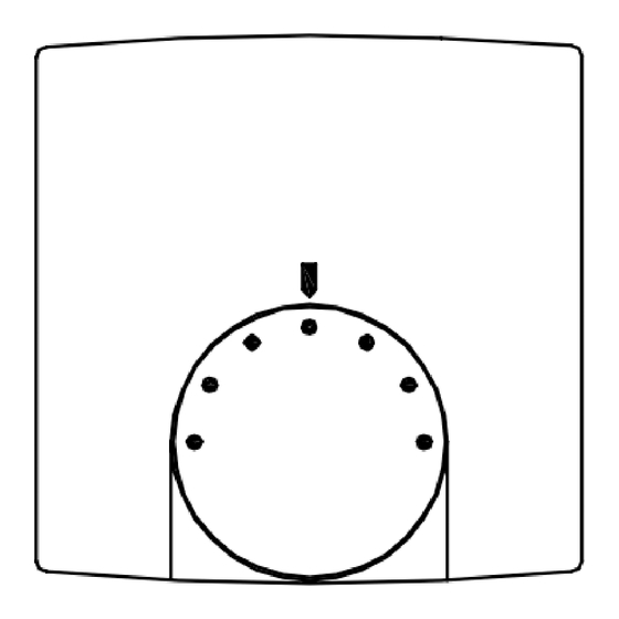
führung wird eine sehr genaue Schaltdifferenz erreicht. Bereichseinengung siehe Bild 2. Bei
Beschalten der Klemme
mit 230 V~ wird auf eine um ca. 3K geringere Temperatur
geregelt (Nachtabsenkung).
3. Montage/Anschluss
Auslieferungszustand offen. Montage wegen des geringen Verdrahtungsraumes auf eine
UP-Dose empfohlen, kann aber auch auf ebenen nichtleitfähigen Untergrund erfolgen.
Öffnen und Schließen wie in Bild 1 beschrieben. Die zur Wand zeigenden, verdeckten
Lüftungsschlitze dürfen nicht verschlossen werden, da dies zu einer fehlerhaften Regelung
führt.
Achtung! Der Regler ist für übliche Verunreinigungen in Wohn- und Büroräumen geeignet.
Unverhältnismäßiger Schmutz und Staub während der Installations- oder Renovierungs-
arbeiten kann die Kontakte verschmutzen und zur Nichtfunktion des Reglers führen.
Achtung! Den Einstellknopf immer erst vor dem Abnehmen des Gehäusedeckels abziehen!
Der Einstellknopf darf nicht ohne vorheriges Aufsetzen des Gehäusedeckels aufgesteckt
und wieder abgezogen werden!
Bild 1 / picture 1 / illustration 1
4 4 . . T T e e c c h h n n i i s s c c h h e e D D a a t t e e n n
Fühlerelement / Kontakt:
Versorgungsspannung und Schaltvermögen: 250 V~, 2(1)A
Regelbereich:
Schaltdifferenz:
max. zulässige Temperatur-
änderungsgeschwindigkeit der Regelstrecke: 4 K/h
Schutzart:
Schutzklasse:
Max. Luftfeuchtigkeit:
Gehäusematerial und -Farbe:
5. Verwendete Symbole
Symbol
Erklärung
L
Phase Versorgungs- und Schaltspannung
N
Neutralleiter Versorgung und Verbraucher
Ausgang Heizen
Stand 03.201 1 (10/040)
Raumtemperaturregler Bimetall
Bimetal room temperature controller
ambiante
Oberer Schnapphaken
Upper snap-hook
Crochet d'encliquetage
supérieur
Bimetall, Öffner Typ1C
5 ... 30°C (Skala *... 6)
ca. 0,5 K
IP30 nach entsprechender Montage
II nach entsprechender Montage
95%rH, nicht kondensierend
Kunststoff ABS, reinweiß (ähnlich RAL 9010)
Safety information!
D
This bimetal room temperature controller is only to be opened by a qualified electrician and
installed in keeping with the wiring diagram on the housing cover / on the cover / and in the
operating instructions. In so doing, the safety regulations are to be noted. Following instal-
lation, the company concerned is to instruct the operator in the function and operation of
the control system. The operating instructions are to be kept at a place that is easily acces-
sible for both operating and maintenance staff.
1. Application
This bimetal room temperature controller has been specially devised for the control and
supervision of temperatures in offices, living spaces and hotels. Electric floor heating
systems need to be controlled by an additional power contactor. Care must be taken there-
by to ensure that the performance of the controlled system cannot, even if the system is
operated continuously, result in an overheating of the pavement. Up to 10 actuating drives
(normally closed types) can be connected. Where applicable, temperature limiters need to
be installed in addition. Regarding other applications not to be foreseen by the manufactu-
rer of this device, the safety standards concerning these applications need to be followed
and adhered to. Concerning the aptitude of the device for such other applications, please
refer to section 8. in these instructions (Warranty).
2. Functional description
The room temperature controller described herein is equipped with an internal bimetal sen-
sor that captures the currently existing room temperature. The device controls the related
heating or cooling system in accordance with the adjusted set value. A thermal recircula-
tion enables to attain a very precise switching difference. As for the mechanical control
range suppression see picture 2. The room temperature is decreased by approx. 3 K when
connecting the 230V~ power supply to the terminal
3. Mounting / Installation
The controller is delivered in opened condition. As there is only little space available for its
wiring, it is recommended to install the device on an UP box. The controller can nevertheless
be mounted on a non-conductible surface. The opening and closing of the housing takes
place as described in picture 1. The venting slots that point to the wall must not be covered.
If otherwise, there is danger that the control operations performed by the device become
incorrect.
Caution: The device is able to resist to the types of dirt or dust that normally occur in
offices and living spaces. Excessive volumes of dust and/or dirt produced during the instal-
lation or during renovation works may soil the contacts and can lead to a breakdown of the
device.
Caution: Always make sure to pull off the knob only prior to removing the housing cover!
The adjusting knob must neither be put on, nor be pulled off without having put on the
housing cover beforehand!
Einstellfahne
für minimalen
Temperaturwert
setting of the
temperature value
Broche pour
l'ajustage de la
valeur de température
4. Technical data
Sensing element / contact
Supply voltage and switching capacity:
Control range:
Switching difference:
Max. admissible temperature changing
speed of the controlled system:
Degree of protection:
Protection class:
Max. admissible air moisture:
Housing material and colour:
5. Explanation of symbols
Symbol
Explanation
L
Supply and switching voltage (phase)
N
Supply and consumers (neutral conductor)
Heating output
(night temperature decrease).
Pin for the
minimum
minimale
Bild 2 / picture 2 / illustration 2
bimetal sensor type 1C / break contact
250 V~, 2(1) A
5 ... 30°C (scale *... 6)
approx. 0.5 K
4 K/h
IP30 (after according installation)
II (after according installation)
95%rh, non-condensing
plastic (ABS), pure white (similar to RAL 9010)
GB
Einstellfahne
für maximalen
Temperaturwert
Pin for the
setting of the
maximum
temperature value
Broche pour
l'ajustage de la
valeur de
température
maximale
4 12 881 00
Werbung

Verwandte Anleitungen für Halmburger RT-A10f


Inhaltszusammenfassung für Halmburger RT-A10f
- Seite 1 RT-A10f Raumtemperaturregler Bimetall Bimetal room temperature controller Thermostat électronique pour la régulation de la température ambiante Sicherheitshinweis! Safety information! Dieses Gerät darf nur durch eine Elektrofachkraft geöffnet und gemäß dem entsprechenden This bimetal room temperature controller is only to be opened by a qualified electrician and Schaltbild im Gehäusedeckel / auf dem Gehäuse / in der Bedienungsanleitung installiert...
- Seite 2 Nous n’assumons aucune garantie à cet égard. Sous réserve de modifications techniques. Halmburger GmbH – Wasserburger Straße 8 – 84427 Sankt Wolfgang/Obb. – Tel.: 0 80 85/1879-0 – Fax: 0 80 85/1879-79...