Siemens WZU-485E-MOD Bedienungsanleitung
Inhaltsverzeichnis
Verfügbare Sprachen
Verfügbare Sprachen
s
en
Operating instructions
1.
Safety Information
Comply with ESD protection measures.
Avoid short-circuits on the PCB.
When connecting, turn off the mains supply.
Route connecting cables only through the bush
sleeves of the meter.
Do not cut the bush sleeves shorter than necessary
because this may lower the degree of protection.
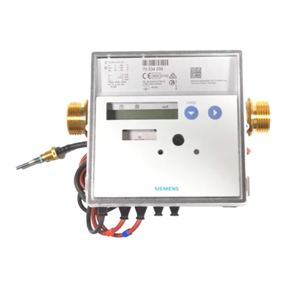
2.
Description of function
WZU-485E-MOD is an add-on communication module for the
following types of meters: UH50.. (firmware 5.15 and higher)
and UC50.. .
The module is intended and preconfigured for data transmis-
sion using the Modbus RTU protocol on RS485.
Note: An external power pack must power the module
(not included in the module's scope of delivery).
3.
Items delivered
1.
Communication module WZU-485E-MOD
2.
Screw connector for RS485 interface and power supply
4.
Installation and assembly
Up to 2 communication modules can be installed.
Siemens Smart Infrastructure
Modbus module WZU-485E-MOD
Number
1
2
3
4
5
Installing the communication module
The communication modules are connected via a 6-pole reac-
tion-free connector so that installation or replacement is possi-
ble at any time.
To install a communication module proceed as follows:
•
•
•
•
•
•
•
•
•
A6V12318603
----_a
_
Description
Service button (under the housing cover)
Slot "module 1"
Slot "module 2"
Bushing for power cable
Cable grommets
Note: WZU-485E-MOD may only be combined with
an M-Bus module in slot "module 2". Only one of them
may be operated in fast read-out mode with an up-
date interval shorter than 15 min.
Press the 4 side lugs of the housing cover inwards and
remove the cover.
Put the communication module into the correct position.
Note: The module WZU-485E-MOD may only be
fitted at slot "module 1".
Place the communication module carefully in both guide
slots and push it in.
Wait for the module indication on the meter display (Loop 4:
"Modul1 MI / G4").
To connect the power supply and the communication cable
of WZU-485E-MOD, open 2 sleeves matching the cross
section of the respective cables.
Note: Open the cable sleeves in such a way that they
enclose the cable tightly.
Guide cables through the bush sleeves from the outside.
Connect the the power supply to terminals 24V and GND,
and the communication cable to terminals A+ and B-.
Note: For the connection to the screw terminal, a slot
screwdriver with 2.5 mm tip is needed.
Attention: Do not connect the the power supply to
terminals A+ and B-. This may cause permanent
damage to the module.
Insert the screw connector into its counterpart on the com-
munication module.
Secure the cables with the metal strain relief.
_----_a
A6V12318603
2021-01-28
Original language
2021-01-28
1
Inhaltsverzeichnis

Verwandte Anleitungen für Siemens WZU-485E-MOD


Inhaltszusammenfassung für Siemens WZU-485E-MOD
-
Seite 5: Sicherheitshinweise
Steckplatz „Modul 1“ Steckplatz „Modul 2“ Netzleitungsdurchführung Durchführungstüllen Hinweis: Das WZU-485E-MOD darf nur mit einem M- Bus Modul auf Steckplatz „Modul 2“ kombiniert wer- den. Nur eines der beiden Module darf im Schnellaus- lesemodus mit einem Aktualisierungsintervall kleiner 15 Min. betrieben werden. -
Seite 6: Lcd-Anzeige
Verbinden Sie das Modul mit einem PC mit Hilfe des USB- Leistungsaufnahme <50mA (typisch <20 mA bei 24 V) Kabels. Empfohleme Absicherung 100 mA träge • Starten Sie die Software „WZU-485 Configuration Tool”. Galvanische Trennung Vom Zähler Vom RS485 Netzwerk Nein Siemens Smart Infrastructure A6V12318603 ----_a 2021-01-28... -
Seite 7: Modbus Beschreibung
Das Modul aktualisiert die gespeicherten Zählerdaten binnen 5 Sekunden nach einer Datenanfrage. • Nach einer Datenanfrage mit der Rundrufadresse „0”, aktualisiert das Modul die gespeicherten Zählerdaten, sendet aber keine Antwort. • Das Modul gibt keine Fehlermeldung (exception response) bei ungültigen Datenanfragen zurück. Siemens Smart Infrastructure A6V12318603 ----_a 2021-01-28... - Seite 8 1=kWh Unit =1 m³ = 0,01 MWh Tabelle 3: Header (Datenadresse 13) Siemens Switzerland Ltd Smart Infrastructure Global Headquarters Theilerstrasse 1a CH-6300 Zug © 2021 Siemens Switzerland Ltd. Tel. +41 58 724 2424 www.siemens.com/buildingtechnologies Siemens Smart Infrastructure A6V12318603 ----_a 2021-01-28...