Bosch MS200 Installationsanleitung Für Das Fachhandwerk
Vorschau ausblenden
Andere Handbücher für MS200:
- Installationsanleitung (192 Seiten) ,
- Installationsanleitung für die fachkraft (100 Seiten) ,
- Handbuch (96 Seiten)
Inhaltsverzeichnis
Verfügbare Sprachen
Verfügbare Sprachen
MS 200
[de] Installationsanleitung für das Fachhandwerk. . . . . . . . . . . . . . . . . . . . . . . . . . . . . . 2
[fl]
Installatiehandleiding voor de installateur . . . . . . . . . . . . . . . . . . . . . . . . . . . . . . . 20
[fr]
Notice d'installation pour le professionnel . . . . . . . . . . . . . . . . . . . . . . . . . . . . . . . 38
[it]
Istruzioni per l'installazione per tecnico specializzato . . . . . . . . . . . . . . . . . . . . . . 56
5 6
4
7
3
8
2
9
1
10
0
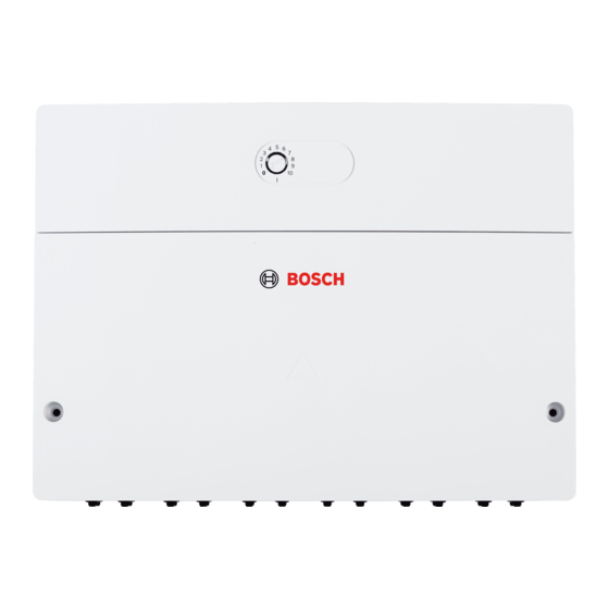
6 720 810 987-00.1O
Kapitel
Inhaltsverzeichnis

Verwandte Anleitungen für Bosch MS200


Inhaltszusammenfassung für Bosch MS200
- Seite 1 6 720 810 987-00.1O MS 200 [de] Installationsanleitung für das Fachhandwerk......2 [fl] Installatiehandleiding voor de installateur .
-
Seite 2: Inhaltsverzeichnis
2 | Inhaltsverzeichnis Inhaltsverzeichnis Symbolerklärung und Sicherheitshinweise Symbolerklärung Symbolerklärung und Sicherheitshinweise ....2 Warnhinweise Symbolerklärung ....... . 2 Allgemeine Sicherheitshinweise . -
Seite 3: Angaben Zum Produkt
Angaben zum Produkt | 3 Elektroarbeiten Angaben zum Produkt Elektroarbeiten dürfen nur Fachleute für Elektroinstallationen ausführen. ▶ Vor Elektroarbeiten: • Das Modul dient zur Ansteuerung der Aktoren (z. B. Pumpen) einer Solaranlage, Umlade- oder Ladesystems. – Netzspannung (allpolig) spannungsfrei schalten und gegen Wiedereinschalten sichern. - Seite 4 4 | Angaben zum Produkt 2. Speicher mit Ventil (B) 2. Speicher mit Vorrang-/ Nachrangregelung über 3-Wege-Ventil ( Bild 23, Seite 81) • Vorrangspeicher wählbar (1. Speicher – oben, 2. Speicher – unten) • Nur wenn der Vorrangspeicher nicht weiter aufgeheizt werden kann, wird über das 3-Wege-Ventil die Spei- cherladung auf den Nachrangspeicher umgeschaltet.
- Seite 5 Angaben zum Produkt | 5 Heizungsunt. gem.(H) ( Solare Heizungsunterstützung gemischt bei Puffer- oder Kombispeicher ( Bild 21, Seite 80) • Nur verfügbar, wenn Heizungsunterstützung (A) oder Heizungsunterstützung Sp. 2 (D) ausgewählt ist. • Funktion wie Heizungsunterstützung (A) oder Heizungsunterstützung Sp. 2 (D); zusätzlich wird die Rück- lauftemperatur über den Mischer auf die vorgegebene Vorlauftemperatur geregelt.
-
Seite 6: Beschreibung Der Umladesysteme Und Umladefunktionen
6 | Angaben zum Produkt Pool (P) Schwimmbadfunktion Funktion wie 2. Speicher mit Ventil (B), 2. Speicher mit Pumpe (C) oder 3. Speicher mit Ventil (N) jedoch für Schwimmbad (Pool). Diese Funktion ist nur verfügbar, wenn Funktion B, C oder N hinzugefügt wurde. HINWEIS: Wenn Funktion Pool (P) hinzugefügt wurde, keinesfalls die Umwälzpumpe/Filterpumpe des Pools am Modul anschließen. -
Seite 7: Lieferumfang
Angaben zum Produkt | 7 Lieferumfang °C °C °C °C Bild 1, Seite 76: – 30 364900 20000 2492 Modul – 20 198400 16090 1816 Speichertemperaturfühler (TS2) – 10 112400 12800 1500 Kollektortemperaturfühler (TS1) 66050 10610 1344 Beutel mit Zugentlastungen 50000... -
Seite 8: Reinigung
8 | Installation • Zusätzlich für thermische Desinfektion (K): Wenn die maximale Kabellänge der BUS-Verbindung zwi- – Pumpe thermische Desinfektion; Anschluss an PS5 schen allen BUS-Teilnehmern überschritten wird oder im • Zusätzlich für Wärmemengenzähler (L): BUS-System eine Ringstruktur vorliegt, ist die Inbetriebnah- –... -
Seite 9: Anschlusspläne Mit Anlagenbeispielen
Installation | 9 Solaranlage MS 200 MS 100 Anschlussplan Die maximale Leistungsaufnahme der angeschlossenen Bild 30, Seite 86 B K P – Bauteile und Baugruppen darf die in den technischen Bild 31, Seite 86 A E J –... -
Seite 10: Überblick Anschlussklemmenbelegung
10 | Installation 3.2.4 Überblick Anschlussklemmenbelegung Dieser Überblick zeigt für alle Anschlussklemmen des Moduls Beispiele, Komplexeren Solaranlagen werden in Kombination mit einem zweiten welche Anlagenteile angeschlossen werden können. Die mit * gekenn- Solarmodul realisiert. Dabei sind vom Überblick der Anschlussklemmen zeichneten Bauteile (z. -
Seite 11: Inbetriebnahme
Inbetriebnahme | 11 Inbetriebnahme der Anlage und des Moduls Inbetriebnahme 4.2.1 Einstellungen bei Solaranlagen 1. Kodierschalter einstellen. HINWEIS: Anlagenschaden durch zerstörte Pumpe! 2. Kodierschalter ggf. an weiteren Modulen einstellen. ▶ Vor dem Einschalten die Anlage befüllen und entlüften, 3. Spannungsversorgung (Netzspannung) der gesamten Anlage ein- damit die Pumpen nicht trocken laufen. -
Seite 12: Konfiguration Der Solaranlage
12 | Inbetriebnahme Konfiguration der Solaranlage ▶ Zurück-Taste drücken, um zur bis dahin konfigurierten Anlage zu springen. ▶ Menü Einstellungen Solar > Solarkonfiguration ändern im ▶ Um eine Funktion zu löschen: Servicemenü öffnen. – Auswahlknopf drehen, bis im Display der Text Löschen der ▶... -
Seite 13: Übersicht Des Servicemenüs
Inbetriebnahme | 13 Übersicht des Servicemenüs Die Menüs sind von der installierten Bedieneinheit und der installierten Anlage abhängig. Servicemenü Servicemenü Inbetriebnahme Inbetriebnahme Heizungsunterstützung Heizungsunterstützung Einstellungen Warmwasser Einstellungen Warmwasser Einschaltdiff. Heiz.unterst. Einschaltdiff. Heiz.unterst. Warmwassersystem I Warmwassersystem I Einstellungen Solar Einstellungen Solar Ausschaltdiff. -
Seite 14: Menü Einstellungen Solarsystem (System 1)
14 | Inbetriebnahme Menü Einstellungen Solarsystem (System 1) Die Grundeinstellungen sind in den Einstellbereichen hervorgehoben. HINWEIS: Anlagenschaden durch zerstörte Pumpe! ▶ Vor dem Einschalten die Anlage befüllen und entlüf- ten, damit die Pumpen nicht trocken laufen. Die folgende Tabelle stellt kurz das Menü Einstellungen Solar dar. Die Menüs und die darin verfügbaren Einstellungen sind auf den folgenden Seiten ausführlich beschrieben. - Seite 15 Inbetriebnahme | 15 Menüpunkt Einstellbereich Funktionsbeschreibung Ausschaltdiff. Solarp. 2 3 ... 5 ... 17 K Wenn die Kollektortemperatur die Speichertemperatur um die hier eingestellte Differenz unterschreitet, ist die Solar- pumpe 2 aus (min. 3 K kleiner als Einschaltdiff. Solarpumpe2). Max. Kollektortemp. 100 ...
-
Seite 16: Heizungsunterstützung
16 | Inbetriebnahme Heizungsunterstützung ( Menüpunkt Einstellbereich Funktionsbeschreibung Einschaltdiff. Heiz.unterst. 6 ... 20 K Wenn die hier eingestellte Differenz zwischen Speichertemperatur und Heizungsrücklauf überschritten wird und alle Einschaltbedingungen erfüllt sind, ist der Speicher über das 3-Wege-Ventil in den Heizungsrücklauf zur Heizungsunterstützung eingebunden. - Seite 17 Inbetriebnahme | 17 Umladung Menüpunkt Einstellbereich Funktionsbeschreibung Umladung Einschaltdiff. 6 ... 10 ... 20 K Wenn die hier eingestellte Differenz zwischen 1. Speicher und 3. Speicher überschritten wird und alle Ein- schaltbedingungen erfüllt sind, ist die Umladepumpe an. Umladung Ausschaltdiff. 3 ...
-
Seite 18: Solarsystem Starten
18 | Inbetriebnahme 4.5.2 Solarsystem starten Menüpunkt Einstellbereich Funktionsbeschreibung Solarsystem Erst nach Freigabe dieser Funktion läuft die Solaranlage an. starten Bevor Sie das Solarsystem in Betrieb nehmen, müssen Sie: ▶ Das Solarsystem befüllen und entlüften. ▶ Die Parameter für das Solarsystem kontrollieren und, falls erforderlich, auf das installierte Solarsystem abstimmen. Nein Für Wartungszwecke kann die Solaranlage mit dieser Funktion ausgeschaltet werden. -
Seite 19: Menü Info
Tab. 26 Störungen beheben Umweltschutz/Entsorgung Nur Originalersatzteile verwenden. Schäden, die durch Umweltschutz ist ein Unternehmensgrundsatz der Bosch Gruppe. nicht vom Hersteller gelieferte Ersatzteile entstehen, sind Qualität der Produkte, Wirtschaftlichkeit und Umweltschutz sind für uns von der Haftung ausgeschlossen. gleichrangige Ziele. Gesetze und Vorschriften zum Umweltschutz wer- Wenn sich eine Störung nicht beheben lässt, bitte an den... - Seite 76 76 | Protezione dell'ambiente/Smaltimento 6 720 647 922-43.1O Fig. 3 6 720 647 922-44.1O 6 mm 6 mm 3,5 mm 6 720 647 922-42.3O Fig. 1 Fig. 4 ... mm 6 mm 6 mm 3,5 mm 6 720 647 922-41.1o Fig.
- Seite 77 Protezione dell'ambiente/Smaltimento | 77 6 720 647 922-49.1O 6 720 647 922-53.1O Fig. 6 Fig. 9 6. 6. 7. 7. 5. 5. 6 720 647 922-54.2O 6 720 647 922-47.2O Fig. 7 Fig. 10 6. 6. 7. 7. 5. 5. 6 720 647 922-48.2O 6 720 647 922-55.1O Fig.
- Seite 78 78 | Protezione dell'ambiente/Smaltimento 4. 4. 2. 2. 3. 3. 1. 1. 6 720 647 922-56.1O 6 720 647 922-59.1O Fig. 12 Fig. 15 2. 2. 8. 8. 5. 5. 9. 9. 3. 3. 6. 6. 100 mm 100 mm 7.
- Seite 79 Protezione dell'ambiente/Smaltimento | 79 6 720 647 922-51.1O Fig. 19 6 720 647 922-46.2O Fig. 17 6 720 647 922-50.1O Fig. 18 MS 200 6 720 819 871 (2016/10)
- Seite 80 80 | Protezione dell'ambiente/Smaltimento MS 200 4 5 6 120/230 V AC ≤ 24 V 4 5 6 TS4 TS5 N 43 N 63 1 2 1 2 1 2 3 4 1 120/230 V AC ≤ 24 V TS1 TS2 VS1/PS2/PS3 120/230VAC 120/230VAC N 74...
- Seite 81 Protezione dell'ambiente/Smaltimento | 81 MS 200 4 5 6 120/230 V AC ≤ 24 V 4 5 6 TS4 TS5 N 43 N 63 1 2 1 2 1 2 3 4 1 VS1/PS2/PS3 VS1/PS2/PS3 VS1/PS2/PS3 120/230 V AC ≤ 24 V N 74 75 N 74 75 N 74 75...
- Seite 82 82 | Protezione dell'ambiente/Smaltimento G H K MS 200 4 5 6 120/230 V AC ≤ 24 V 4 5 6 TS4 TS5 N 43 N 63 1 2 1 2 1 2 3 4 1 VS1/PS2/PS3 VS1/PS2/PS3 VS1/PS2/PS3 120/230 V AC ≤...
- Seite 83 Protezione dell'ambiente/Smaltimento | 83 D H K MS 200 4 5 6 120/230 V AC ≤ 24 V 4 5 6 TS4 TS5 N 43 N 63 1 2 1 2 1 2 3 4 1 VS1/PS2/PS3 VS1/PS2/PS3 VS1/PS2/PS3 120/230 V AC ≤...
- Seite 84 ≤ 24 V 4 5 6 TS4 TS5 4 5 6 N 43 N 63 1 2 1 2 1 2 3 4 1 MS200 VS1/PS2/PS3 VS1/PS2/PS3 VS1/PS2/PS3 120/230 V AC ≤ 24 V N 74 75 N 74 75...
- Seite 85 Protezione dell'ambiente/Smaltimento | 85 B D F I G H K MS 200 MS 100 4 5 6 4 5 6 MS 200 4 5 6 4 5 6 120/230 V AC ≤ 24 V TS4 TS5 N 43 N 63 1 2 1 2 1 2 3 4 1 120/230 V AC...
- Seite 86 86 | Protezione dell'ambiente/Smaltimento TS10 TS11 B K P MS 200 4 5 6 120/230 V AC ≤ 24 V 4 5 6 TS4 TS5 N 43 N 63 1 2 1 2 1 2 3 4 1 120/230 V AC ≤...
- Seite 87 Protezione dell'ambiente/Smaltimento | 87 TS10 A B E J G K M P TS11 MS 200 MS 100 TS14 TS15 4 5 6 4 5 6 MS 200 4 5 6 4 5 6 120/230 V AC ≤ 24 V TS4 TS5 N 43 N 63...
- Seite 88 88 | Protezione dell'ambiente/Smaltimento TS10 1 A C E J K M P TS11 MS 200 MS 100 TS14 TS15 4 5 6 4 5 6 MS 200 4 5 6 4 5 6 120/230 V AC ≤ 24 V TS4 TS5 N 43 N 63...
- Seite 89 Protezione dell'ambiente/Smaltimento | 89 TS16 1 B D N P MS 200 4 5 6 120/230 V AC ≤ 24 V 4 5 6 TS4 TS5 N 43 N 63 1 2 1 2 1 2 3 4 1 VS1/PS2/PS3 VS1/PS2/PS3 VS1/PS2/PS3 120/230 V AC...
- Seite 90 90 | Protezione dell'ambiente/Smaltimento 1 B D F N P G H K M TS16 MS 200 MS 100 TS14 TS15 4 5 6 4 5 6 MS 200 4 5 6 4 5 6 120/230 V AC ≤ 24 V TS4 TS5 N 43 N 63...
- Seite 91 Protezione dell'ambiente/Smaltimento | 91 TS16 1 B N Q MS 200 4 5 6 120/230 V AC ≤ 24 V 4 5 6 TS4 TS5 N 43 N 63 1 2 1 2 1 2 3 4 1 120/230 V AC ≤...
- Seite 92 92 | Protezione dell'ambiente/Smaltimento TS12 ..L MS 200 4 5 6 TS13 120/230 V AC ≤ 24 V 4 5 6 TS4 TS5 N 43 N 63 1 2 1 2 1 2 3 4 1 120/230 V AC ≤...
- Seite 93 Protezione dell'ambiente/Smaltimento | 93 TS17 TS19 PS13 MS 200 PS11 4 5 6 PS12 TS18 120/230 V AC ≤ 24 V TS4 TS5 N 43 N 63 1 2 1 2 1 2 3 4 120/230 V AC ≤ 24 V TS1 TS2 VS1/PS2/PS3 120/230VAC 120/230VAC...
- Seite 94 94 | Protezione dell'ambiente/Smaltimento Fig. 42 6 720 819 871 (2016/10) MS 200...
- Seite 95 Protezione dell'ambiente/Smaltimento | 95 MS 200 6 720 819 871 (2016/10)
- Seite 96 Bosch Thermotechnik GmbH Junkersstrasse 20-24 D-73249 Wernau www.bosch-thermotechnology.com...