Inhaltsverzeichnis
Werbung
Verfügbare Sprachen
Verfügbare Sprachen
Quicklinks
GB
IT
FR
DE
TR
Downloaded from
www.Manualslib.com
Instructions for use and installation
Cooker Hood
Istruzioni per l'uso e l'installazione
Cappa
Mode d'emploi et installation
Hotte de Cuisine
Bedienungsanleitung und Einrichtung
Dunstabzugshaube
Kullanım ve montaj talimatları
Davlumbaz
manuals search engine
FDB 6078
FDB 7078
FDB 8078
FDB 9078
Werbung
Inhaltsverzeichnis

Verwandte Anleitungen für Franke FDB 6078


Inhaltszusammenfassung für Franke FDB 6078
- Seite 1 Instructions for use and installation Cooker Hood Istruzioni per l’uso e l’installazione Cappa Mode d’emploi et installation Hotte de Cuisine Bedienungsanleitung und Einrichtung Dunstabzugshaube Kullanım ve montaj talimatları Davlumbaz FDB 6078 FDB 7078 FDB 8078 FDB 9078 Downloaded from www.Manualslib.com manuals search engine...
-
Seite 2: Inhaltsverzeichnis
Instructions Manual INDEX RECOMMENDATIONS AND SUGGESTIONS ........................7 CHARACTERISTICS................................8 INSTALLATION ..................................9 USE.......................................12 MAINTENANCE..................................13 Downloaded from www.Manualslib.com manuals search engine... -
Seite 3: Libretto Di Istruzioni
Libretto di Istruzioni INDICE CONSIGLI E SUGGERIMENTI ............................16 CARATTERISTICHE ................................17 INSTALLAZIONE..................................18 USO ......................................21 MANUTENZIONE .................................22 Downloaded from www.Manualslib.com manuals search engine... - Seite 4 Manuel d’Instructions SOMMAIRE CONSEILS ET SUGGESTIONS ............................25 CARACTERISTIQUES .................................26 INSTALLATION ..................................27 UTILISATION..................................30 ENTRETIEN..................................31 Downloaded from www.Manualslib.com manuals search engine...
- Seite 5 Bedienungsanleitung INHALTSVERZEICHNIS EMPFEHLUNGEN UND HINWEISE............................34 CHARAKTERISTIKEN................................35 MONTAGE....................................36 BEDIENUNG..................................39 WARTUNG....................................40 Downloaded from www.Manualslib.com manuals search engine...
- Seite 6 Kullanim Kilavuku IÇERIKLER TAVSIYELER VE ÖNERILER ..............................43 ÖZELLIKLER ..................................44 MONTAJ ....................................45 KULLANIM ....................................48 BAKIM....................................49 Downloaded from www.Manualslib.com manuals search engine...
-
Seite 7: Recommendations And Suggestions
RECOMMENDATIONS AND SUGGESTIONS The Instructions for Use apply to several versions of this appliance. Accord- ingly, you may find descriptions of individual features that do not apply to your specific appliance. INSTALLATION • The manufacturer will not be held liable for any damages resulting from incor- rect or improper installation. -
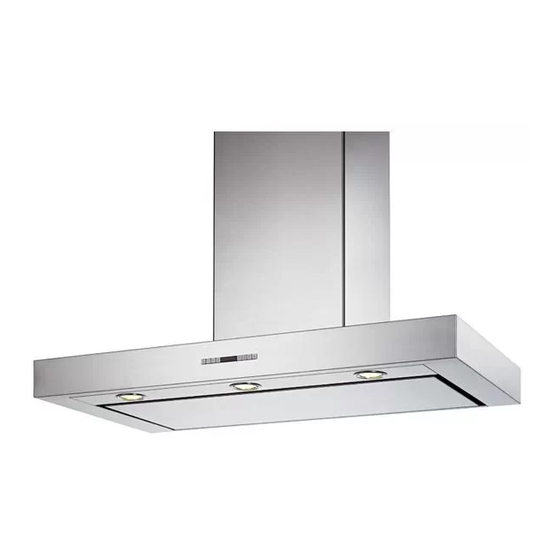
Seite 8: Characteristics
CHARACTERISTICS Dimensions Components 14.1 Ref. Q.ty Product Components Hood Body, complete with: Controls, Light, Blower, 12a 7.2.1 Filters Telescopic Chimney comprising: Upper Section Lower Section Reducer Flange ø 150-120 mm 14.1 Air Outlet Connection Extension Air Outlet Connection Ref. Q.ty Installation Components 7.2.1 Upper Chimney Section Fixing Brackets Air Outlet Connection Support... -
Seite 9: Installation
INSTALLATION Wall drilling and bracket fixing 7.2.1 Wall marking: • Draw a vertical line on the supporting wall up to the ceiling, or as high as practical, at the centre of the area in which the hood will be installed. •... - Seite 10 Mounting the hood body • Before attaching the hood body, tighten the two screws Vr lo- cated on the hood body mounting points. • Hook the hood body onto the screws 12a. • Fully tighten support screws 12a. • Adjust screws Vr to level the hood body. Connections DUCTED VERSION AIR EXHAUST SYSTEM ø...
-
Seite 11: Electrical Connection
ELECTRICAL CONNECTION • Connect the hood to the mains through a two-pole switch hav- ing a contact gap of at least 3 mm. • Remove the grease filters (see paragraph Maintenance) being sure that the connector of the feeding cable is correctly inserted in the socket placed on the side of the fan. -
Seite 12: Use
Control board Function Display Switches the extractor motor on and off at the Indicates the selected speed. latest selected speed Decreases the suction speed. Increases the suction speed. By pressing this key it is possible to activate HI appears. The spot down on the right side the intensive speed from any previously se- flashes once a second. -
Seite 13: Maintenance
MAINTENANCE REMOTE CONTROL (OPTIONAL) The appliance can be controlled using a remote control powered by a 1.5 V carbon-zinc alkaline batteries of the standard LR03- AAA type. • Do not place the remote control near to heat sources. • Used batteries must be disposed of in the proper manner. Cleaning the Comfort Panels •... - Seite 14 Metal grease filters Filters can be washed in the dish machine. They need to be washed when FF-sign appears on the display or in any case every 2 months, or even more frequently in case of particularly inten- sive use of the hood. Alarm reset •...
-
Seite 15: Light Replacement
Charcoal filter (recycling version) • This filter cannot be washed or regenerated. It must be replaced when the EF appears on the display or at least once every 4 months. Activation of the alarm signal • In the recycling version hoods the filter saturation alarm must be activated during the instal- lation or later. -
Seite 16: Consigli E Suggerimenti
CONSIGLI E SUGGERIMENTI Questo libretto di istruzioni per l'uso è previsto per più versioni dell' apparec- chio. É possibile che siano descritti singoli particolari della dotazione, che non riguardano il Vostro apparecchio. INSTALLAZIONE • Il produttore declina qualsiasi responsabilità per danni dovuti ad installazione non corretta o non conforme alle regole dell’arte. -
Seite 17: Caratteristiche
CARATTERISTICHE Ingombro Componenti 14.1 Rif. Q.tà Componenti di Prodotto Corpo Cappa completo di: Comandi, Luce, Gruppo 12a 7.2.1 Ventilatore, Filtri Camino Telescopico formato da: Camino Superiore Camino Inferiore Flangia di Riduzione ø 150-120 mm 14.1 Prolunga Raccordo Uscita Aria Raccordo Uscita Aria Rif. -
Seite 18: Installazione
INSTALLAZIONE Foratura Parete e Fissaggio Staffe 7.2.1 Tracciare sulla Parete: • una linea Verticale fino al soffitto o al limite superiore, al centro della zona prevista per il montaggio della Cappa; • una linea Orizzontale a: 650 mm min. sopra il Piano di Cottura. •... - Seite 19 Montaggio Corpo Cappa • Prima di agganciare il Corpo Cappa, serrare le 2 Viti Vr situate sui punti di aggancio del Corpo Cappa. • Agganciare il Corpo Cappa alle Viti 12a. • Serrare definitivamente le Viti 12a di supporto. • Agire sulle Viti Vr per livellare il Corpo Cappa. Connessioni USCITA ARIA VERSIONE ASPIRANTE ø...
-
Seite 20: Connessione Elettrica
CONNESSIONE ELETTRICA • Collegare la Cappa all’Alimentazione di Rete interponendo un Interruttore bipolare con apertura dei contatti di almeno 3 mm. • Rimuovere i Filtri antigrasso (vedi par. “Manutenzione”) e as- sicurarsi che il connettore del Cavo di alimentazione sia corret- tamente inserito nella presa dell’Aspiratore 7.2.1 Montaggio Camino... -
Seite 21: Uso
Quadro comandi Tasto Funzione Display Accende e spegne il motore di aspirazione Visualizza la velocità impostata all’ultima velocità utilizzata. Decrementa la velocità di esercizio. Incrementa la velocità di esercizio. Attiva la velocità intensiva da qualsiasi velo- Visualizza HI e il punto in basso a destra lam- cità... -
Seite 22: Manutenzione
MANUTENZIONE TELECOMANDO (OPZIONALE) Questo apparecchio può essere comandato per mezzo di un tele- comando, alimentato con pile alcaline zinco-carbone da 1,5 V del tipo standard LR03-AAA. • Non riporre il telecomando in prossimità di fonti di calore. • Non disperdere le pile nell’ambiente, depositarle negli appositi contenitori. - Seite 23 Filtri antigrasso metallici Sono lavabili anche in lavastoviglie, e necessitano di essere lavati quando sul display appare FF o almeno ogni 2 mesi circa di uti- lizzo o più frequentemente, per un uso particolarmente intenso. Reset del segnale di allarme •...
-
Seite 24: Sostituzione Lampade
Filtri antiodore al Carbone attivo (Versione Filtrante) • Non è lavabile e non è rigenerabile, va sostituito quando sul display appare EF o almeno ogni 4 mesi. Attivazione del segnale di allarme • Nelle Cappe in Versione Filtrante, la segnalazione di Allarme saturazione Filtri va attivata al momento dell’installazione o successivamente. -
Seite 25: Conseils Et Suggestions
CONSEILS ET SUGGESTIONS La présente notice d'emploi vaut pour plusieurs versions de l'appareil. Elle peut contenir des descriptions d'accessoires ne figurant pas dans votre ap- pareil. INSTALLATION • Le fabricant décline toute responsabilité en cas de dommage dû à une installation non correcte ou non conforme aux règles de l’art. - Seite 26 CARACTERISTIQUES Encombrement Composants 14.1 Réf. Q.té Composants de Produit Corps Hotte équipé de:Commandes, Lumière, Groupe 12a 7.2.1 Ventilateur,Filtres Cheminée Télescopique formée de : Cheminée Supérieure Cheminée Inférieure Flasque de Réduction ø 150-120 mm 14.1 Rallonge Raccord Sortie Air Raccord Sortie Air Réf.
- Seite 27 INSTALLATION Perçage Paroi et Fixation Brides 7.2.1 Tracer sur la paroi: • une ligne verticale allant jusqu’au plafond ou à la limite supérieure, au centre de la zone prévue pour le montage de la hotte; • une ligne horizontale à 650 mm min. au-dessus du plan de cuisson. •...
- Seite 28 Montage Corps Hotte • Avant d’accrocher le corps hotte, serrer les deux vis Vr situées sur les points d’accrochage du corps hotte. • Accrocher le corps hotte aux vis 12a prévues à cet effet. • Serrer définitivement les vis 12a de support. •...
-
Seite 29: Branchement Electrique
BRANCHEMENT ELECTRIQUE • Brancher la hotte sur le secteur en interposant un interrupteur bipolaire avec ouverture des contacts d’au moins 3 mm. • Enlever les filtres à graisse (voir § "Entretien") et s'assurer que le connecteur du câble d'alimentation soit bien branché dans la prise du diffuseur. - Seite 30 UTILISATION Tableau des commandes Touche Fonction Afficheur Allume et éteint le moteur d’aspiration à la Affiche la vitesse choisie dernière vitesse utilisée Diminue la vitesse de service Augmente la vitesse de service Active la vitesse intensive à partir de Affiche HI et le point en bas à droite clignote n’importe quelle vitesse, même du moteur une fois par seconde.
- Seite 31 ENTRETIEN TELECOMMANDE (FOURNIE SUR DEMANDE) Il est possible de commander cet appareil au moyen d’une télé- commande, alimentée avec des piles alcalines zinc-charbon 1,5 V du type standard LR03-AAA. • Ne pas ranger la télécommande à proximité de sources de cha- leur.
- Seite 32 Filtres à graisse métalliques Ils sont lavables même en lave-vaisselle et doivent être lavés chaque fois que le symbole FF s’affiche ou environ tous les 2 mois ou plus souvent même, en cas d’utilisation particulièrement intensive. Rétablissement du signal d’alarme •...
- Seite 33 Filtre anti-odeur au charbon actif (version filtrante) • Il ne peut être ni lavé ni récupéré, il faut le changer quand EF s’affiche ou au moins tous les 4 mois. Déclenchement du signal d’alarme • Pour les Hottes en Version Filtrante, l’alarme indiquant la saturation des Filtres doit être activée au moment de l’installation ou ultérieurement.
-
Seite 34: Empfehlungen Und Hinweise
EMPFEHLUNGEN UND HINWEISE Diese Gebrauchsanleitung gilt für mehrere Geräte-Ausführungen. Es ist möglich, dass einzelne Ausstattungsmerkmale beschrieben sind, die nicht auf Ihr Gerät zutreffen. MONTAGE • Das Gerät darf nur vom Fachpersonal angeschlossen werden. • Der Hersteller haftet nicht für Schäden, die auf eine fehlerhafte und unsachgemäße Mon- tage zurückzuführen sind. - Seite 35 CHARAKTERISTIKEN Platzbedarf Komponenten 14.1 Pos. Produktkomponenten Haubenkörper mit Schaltern, Beleuchtung, Gebläse- 12a 7.2.1 gruppe, Filter Teleskopkamin bestehend aus: oberer Kaminteil unterer Kaminteil Reduzierflansch ø 150-120 mm 14.1 Verlängerung Luftaustritt-Anschlussstück Luftaustritt-Anschlussstück Pos. Montagekomponenten 7.2.1 Befestigungsbügel oberer Kaminteil Bügel für Anschlusshalter Dübel Schrauben 4,2 x 44,4 Schrauben 2,9 x 9,5 Dokumentation...
- Seite 36 MONTAGE Bohren der Befestigungslöcher und Fixieren der Befestigungsbügel 7.2.1 Achtung: Bitte beachten Sie bei der Montage das Gewicht der kompletten Haube. Die Tragfä- higkeit der Decke oder alternativ der Trägerplatte für diese Zugbelastung muss vor der Mon- tage geprüft und gegebenenfalls durch die Anbringung von geeigneten Befestigungs- oder Stabilisierungselementen hergestellt werden.
- Seite 37 Montage des Haubenkörpers • Bevor der Haubenkörper eingehakt wird, die 2 Schrauben Vr bei den Haubenkörper-Anhakpunkten festziehen. • Den Haubenkörper bei den Schrauben 12a einhängen. • Die Halteschrauben 12a definitiv festziehen. • Den Haubenkörper mit Hilfe der Schrauben Vr ausrichten. Anschluss der Abluftversion Bei Abluftbetrieb kann die Haube vom Installateur wahlweise ø...
- Seite 38 Elektroanschluss Vor der Installation die Netzspannung durch herausdrehen der Sicherung oder ausschalten des Hauptschalters stromlos ma- chen. • Bei Anschluss der Haube an das Stromnetz muss ein zweipoliger Schalter einem Öffnungsweg mindestens 3 mm zwischengeschaltet werden. • Entfernen Sie die Fettfilter (s. Abschnitt „Wartung“) und versichern Sie sich, daß...
-
Seite 39: Bedienung
BEDIENUNG Bedienblende Taste Funktion Display Schaltet den Motor der Absauganlage bei der Zeigt die eingestellte Geschwindigkeit an zuletzt verwendeten Geschwindigkeit ein und aus. Vermindert die Betriebsgeschwindigkeit. Erhöht die Betriebsgeschwindigkeit. Aktiviert von jeder Geschwindigkeit aus, auch Zeigt HI an und der Punkt unten rechts blinkt bei abgestelltem Motor, die Intensivgeschwin- einmal pro Sekunde. -
Seite 40: Wartung
WARTUNG FERNBEDIENUNG (OPTION) Dieses Gerät kann mit einer Fernbedienung gesteuert werden, welche mit alkalischen Zink-Kohle-Batterien 1,5 V des Standard- typs LR03-AAA versorgt wird. • Die Fernbedienung nicht in die Nähe von Hitzequellen legen. • Batterien müssen vorschriftsmäßig entsorgt werden. Reinigung der Comfort Panel •... - Seite 41 Metallfettfilter Die Fettfilter sind spülmaschinengeeignet und müssen gewaschen werden, sobald am Display die Aufschrift FF erscheint oder mindestens alle 2 Monate, oder auch öfter, je nach Intensität des Gebrauchs. Reset des Alarmsignals • Die Beleuchtung und den Absaugmotor abschalten und dann die 24-Stunden-Funktion deaktivieren, falls diese zuvor aktiv war.
-
Seite 42: Auswechseln Des Aktivkohle-Geruchsfilters
Aktivkohle-Geruchsfilter (Filterversion) • Der Aktivkohlefilter ist weder waschbar, noch regenerierbar und muss ausgewechselt wer- den, wenn am Display die Aufschrift EF erscheint, oder nach mindestens 4 Monaten. Aktivierung des Alarmsignals • Bei den Filterversionen der Abzugshauben wird die Alarmanzeige für Filtersättigung im Augenblick der Installation oder in der Folge aktiviert. -
Seite 43: Tavsiyeler Ve Öneriler
TAVSIYELER VE ÖNERILER Bu kullanma talimatι birden fazla cihaz modeli için geçerlidir. Cihazιnιza uymayan bazι donanιm özellikleri tarif edilmiş olabilir. MONTAJ • Yalnιş veya eksik montajdan doğan herhangi bir zararιn sorumluluğu üre- ticiye ait değildir. • Davlumbaz ile pişirici cihazιn ocak kιsmι arasιndaki minimum güvenlik mesafesi 650 mm.dir. - Seite 44 ÖZELLIKLER Boyutlar Parçalar 14.1 Ref. Adet Ürünün parçaları Şunlardan oluşan davlumbaz gövdesi: Kumandalar, 12a 7.2.1 Lamba, Fan grubu, Filtreler Şunlardan oluşan teleskopik baca: Üst baca Alt baca Redüksiyon Flanşı ø 150-120 mm 14.1 Hava Çıkışı Uzatma Rakoru Hava Çıkışı Rakoru Ref.
- Seite 45 MONTAJ Duvarın Delinmesi ve Braketlerin Sabitlenmesi 7.2.1 Duvara şunları çiziniz: • Tavana yada üst sınıra kadar uzunan Dikey bir çizgi: Davlumbazın monte edileceği yerin tam merkezinden geçmelidir; • Tezgâh (setüstü ocak) yüzeyinden 650 mm mesafeden geçen bir Yatay çizgi. • Gösterildiği gibi Braketi 7.2.1 tavandan 1-2 mesafeye dayayınız ve bunun merkezini (çen- tik) Dikey referans çizgisine hizalayınız.
- Seite 46 Davlumbaz Gövdesi Montajı • Davlumbaz Gövdesini kancalara takmadadan önce gövde üze- rindeki kancalama noktalarında bulunan 2 adet vidayı Vr sıkı- nız. • Davlumbaz Gövdesini vidalara 12a takınız. • Destek vidalarını 12a nihai olarak sıkınız. • Vr vidalarına müdahale ederek Davlumbaz Gövdesi seviyesini hizalayınız.
-
Seite 47: Elektri̇k Bağlantisi
ELEKTRİK BAĞLANTISI • Davlumbazı şebeke cereyanına bağlarken aray temas aralığı en az 3 mm olan çift kutuplu bir elektrik anahtarı koyunuz. • Yağ tutucu filtreleri çıkarınız (bakınız "Bakım" paragrafı) ve besleme kablosu soketinin aspiratör prizine iyice takılmış ol- duğundan emin olunuz. 7.2.1 Bacanın Montajı... - Seite 48 KULLANIM Kumanda Tablosu Tuş Fonksiyon Gösterge Aspiratör motorunu, kullanılan en son hızda Ayarlanan hızı görüntüler. açıp kapatır. O an devrede olan hızı düşürür. O an devrede olan hızı arttırır. Motor kapalıyken bile herhangi bir hızdan yo- HI işaretini görüntüler ve sağ alttaki nokta sa- ğun hızı...
- Seite 49 BAKIM TELEKUMANDA (OPSİYONEL) Bu cihaza bir telekumanda ile de komut verilebilir; bu kumanda 1,5 Voltluk çinko-karbonlu LR03-AAA tipi standart alkalin pil- lerle çalışır. • Telekumandayı ısı kaynakları yakınında bırakmaynız. • Pilleri çevreye atmayınız, bunlara ayrılmış çöp toplama kapla- rına atınız. Konfor Panelleri’nin Temizlenmesi •...
- Seite 50 Madeni yağ filtreleri Madeni yağ filtreleri, bulaşık makinasında yıkanabilirler. Göster- gede FF işareti görüntülendiğinde ya da en az 2 ayda bir, hatta yoğun kullanımda daha sık aralıklarla yıkanmaları gerekir. Alarm sinyalinin sıfırlanması • Lambaları ve aspiratör motorunu kapatınız. 24h fonksiyonu devrede ise devre dışı...
- Seite 51 Aktif karbonlu koku giderici filtreler (Filtreli Model) • Aktif karbonlu koku giderici filtrelerin yıkanması ve rejenere edilmeleri mümkün değildir, göstergede EF işareti görüntülendiğinde ya da en az 4 ayda bir değiştirilmeleri gerekir. Alarm sinyalinin devreye alınması • Filtrelerin doyum noktasına geldiğini bildiren alarm sinyali montaj sırasında devreye alına- bileceği gibi, Filtreli Model davlumbazlarda daha sonra da devreye alınabilir.
- Seite 52 çevre ve insan sağlığı üzerindeki olumsuz etkilerini bertaraf etmeye katkı sağlamış olursunuz. Bu ürünün geri dönüşüm koşulları hakkında daha ayrıntılı bilgi için hudutları içinde bulunduğunuz belediyenin ilgili diaresine, atık yoketme servisine veya ürünün satıcısına danışınız. Franke S.p.a. Via Pignolini,2 37019 Peschiera del Garda (VR) www.franke.it...