Herunterladen Inhalt Inhalt Diese Seite drucken
Franke FDF 9274 XS-CH Bedienungsanleitung Und Installation

Franke FDF 9274 XS-CH Bedienungsanleitung Und Installation

Vorschau ausblenden Andere Handbücher für FDF 9274 XS-CH:

Werbung

Verfügbare Sprachen

Verfügbare Sprachen

Instructions for use and installation
GB
Cooker Hood
Istruzioni per l'uso e l'installazione
IT
Cappa
Mode d'emploi et installation
FR
Hotte de Cuisine
Bedienungsanleitung und Installation
DE
Dunstabzugshaube
FDF 9274 XS-CH
FDF 12274 XS-CH

Werbung

Inhaltsverzeichnis
loading

Inhaltszusammenfassung für Franke FDF 9274 XS-CH

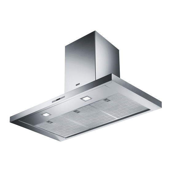
  • Seite 1 Instructions for use and installation Cooker Hood Istruzioni per l’uso e l’installazione Cappa Mode d’emploi et installation Hotte de Cuisine Bedienungsanleitung und Installation Dunstabzugshaube FDF 9274 XS-CH FDF 12274 XS-CH...
  • Seite 2: Inhaltsverzeichnis

    INDEX RECOMMENDATIONS AND SUGGESTIONS ........................3 CHARACTERISTICS ................................6 INSTALLATION ..................................7 USE ...................................... 10 MAINTENANCE ................................... 11 INDICE CONSIGLI E SUGGERIMENTI ............................13 CARATTERISTICHE ................................16 INSTALLAZIONE ................................. 17 USO ...................................... 20 MANUTENZIONE................................. 21 SOMMAIRE CONSEILS ET SUGGESTIONS ............................23 CARACTERISTIQUES .................................
  • Seite 3: Recommendations And Suggestions

    RECOMMENDATIONS AND SUGGESTIONS The Instructions for Use apply to several versions of this appliance. Accordingly, you may find descriptions of individual features that do not apply to your specific appliance. INSTALLATION • The manufacturer will not be held liable for any damages resulting from incorrect or improper installation.
  • Seite 4 • If the instructions for installation for the gas hob specify a greater distance specified above, this has to be taken into account. Regulations concerning the discharge of air have to be fulfilled. • Use only screws and small parts in support of the hood. Warning: Failure to install the screws or fixing device in accordance with these instructions may result in electrical hazards.
  • Seite 5 • “CAUTION: Accessible parts may become hot when used with cooking appliances.” MAINTENANCE • Switch off or unplug the appliance from the mains supply before carrying out any maintenance work. • Clean and/or replace the Filters after the specified time period (Fire hazard). •...
  • Seite 6 CHARACTERISTICS Dimensions 598-698-798-898-1198 Min. Min. 650mm 650mm Components Ref. Q.ty Product Components Hood Body, complete with: Controls, Light, Blower, Filters Telescopic Chimney comprising: Upper Section Lower Section Reducer Flange ø 150-120 mm Air Outlet Connection Ref. Q.ty Installation Components 7.2.1 Upper Chimney Section Fixing Brackets Wall Plugs Screws 4,2 x 44,4...
  • Seite 7 INSTALLATION Wall drilling and bracket fixing 7.2.1 Wall marking: • Draw a vertical line on the supporting wall up to the ceiling, or as high as practical, at the centre of the area in which the hood will be installed. •...
  • Seite 8 Mounting the hood body • Before attaching the hood body, tighten the two screws Vr located on the hood body mounting points. • Hook the hood body onto the screws 12a. • Fully tighten the support screws 12a. • Adjust the screws Vr to level the hood body. Connections DUCTED VERSION AIR EXHAUST SYSTEM When installing the ducted version, connect the hood to the...
  • Seite 9: Electrical Connection

    ELECTRICAL CONNECTION • Connect the hood to the mains through a two-pole switch having a contact gap of at least 3 mm. • Remove the grease filters (see paragraph Maintenance) being sure that the connector of the feeding cable is correctly inserted in the socket placed on the side of the fan.
  • Seite 10: Control Panel

    Control panel Button Function Display Turns the suction motor on and off at speed one. Displays the set speed Decreases the working speed. Displays the set speed Increases the working speed. Displays the set speed Activate intensive speed from any other speed, Displays HI and the time remaining once very second.
  • Seite 11: Remote Control (Optional)

    MAINTENANCE REMOTE CONTROL (OPTIONAL) The appliance can be controlled using a remote control powered by a 1.5 V carbon-zinc alkaline batteries of the standard LR03- AAA type (not included). • Do not place the remote control near to heat sources. •...
  • Seite 12 Activated Charcoal Filter (Recirculation Version) It cannot be washed or regenerated, and must be changed when the FC symbol on the display appears, or at least once every 4 months. The Alarm signal, if it has been activated, only appears when the Suction motor is turned on. Activating the alarm signal •...
  • Seite 13: Consigli E Suggerimenti

    CONSIGLI E SUGGERIMENTI Le Istruzioni per l’uso si riferiscono ai diversi modelli di questo apparecchio. Pertanto, si potrebbero trovare descrizioni di singole caratteristiche che non appartengono al proprio apparecchio specifico. INSTALLAZIONE • Il fabbricante non potrà ritenersi responsabile per eventuali danni risultanti da un’installazione o utilizzazione impropria.
  • Seite 14 • Se le istruzioni di installazione del piano cottura a gas specificano una distanza maggiore di quella sopra indicata, è necessario tenerne conto. Devono essere rispettate tutte le normative riguardanti lo scarico dell'aria. • Usare solo viti e minuteria di tipo idoneo per la cappa. Avvertenza: la mancata installazione delle viti o dei dispositivi di fissaggio in conformità...
  • Seite 15 • “ ATTENZIONE: le parti accessibili possono diventare molto calde durante l’uso degli apparecchi di cottura ”. MANUTENZIONE • Spegnere o scollegare l’apparecchio dalla rete di alimentazione prima di qualunque operazione di pulizia o manutenzione. • Pulire e/o sostituire i filtri dopo il periodo di tempo specificato (pericolo di incendio).
  • Seite 16: Caratteristiche

    CARATTERISTICHE Ingombro 598-698-798-898-1198 Min. Min. 650mm 650mm Componenti Rif. Q.tà Componenti di Prodotto Corpo Cappa completo di: Comandi, Luce, Gruppo Ventilatore, Filtri Camino Telescopico formato da: Camino Superiore Camino Inferiore Flangia di Riduzione ø 150-120 mm Raccordo Uscita Aria Rif. Q.tà...
  • Seite 17 INSTALLAZIONE Foratura Parete e Fissaggio Staffe 7.2.1 Tracciare sulla Parete: • una linea Verticale fino al soffitto o al limite superiore, al centro della zona prevista per il montaggio della Cappa; • una linea Orizzontale a: 650 mm min. sopra il Piano di Cottura. •...
  • Seite 18 Montaggio Corpo Cappa • Prima di agganciare il Corpo Cappa, serrare le 2 Viti Vr situate sui punti di aggancio del Corpo Cappa. • Agganciare il Corpo Cappa alle Viti 12a. • Serrare definitivamente le Viti 12a di supporto. • Agire sulle Viti Vr per livellare il Corpo Cappa. Connessioni USCITA ARIA VERSIONE ASPIRANTE Per installazione in Versione Aspirante collegare la Cappa alla...
  • Seite 19: Connessione Elettrica

    CONNESSIONE ELETTRICA • Collegare la Cappa all’Alimentazione di Rete interponendo un Interruttore bipolare con apertura dei contatti di almeno 3 mm. • Rimuovere i Filtri antigrasso (vedi par. “Manutenzione”) e assicurarsi che il connettore del Cavo di alimentazione sia correttamente inserito nella presa dell’Aspiratore Montaggio Camino 7.2.1 Camino superiore...
  • Seite 20: Quadro Comandi

    Quadro comandi Tasto Funzione Display Accende e spegne il motore di aspirazione alla prima Visualizza la velocità impostata velocità. Decrementa la velocità di esercizio. Visualizza la velocità impostata Incrementa la velocità di esercizio. Visualizza la velocità impostata Attiva la velocità Intensiva da qualsiasi velocità Visualizza alternamente HI e il tempo rimanente una anche da motore spento, tale velocità...
  • Seite 21: Telecomando (Opzionale)

    MANUTENZIONE TELECOMANDO (OPZIONALE) Questo apparecchio può essere comandato per mezzo di un telecomando, alimentato con pile alcaline zinco-carbone da 1,5 V del tipo standard LR03-AAA (non incluse). • Non riporre il telecomando in prossimità di fonti di calore. • Non disperdere le pile nell’ambiente, depositarle negli appositi contenitori.
  • Seite 22 Filtri antiodore al Carbone attivo (Versione Filtrante) Non è lavabile e non è rigenerabile, va sostituito quando sul display appare FC o almeno ogni 4 mesi. La segnalazione di Allarme, se preventivamente attivata, si verifica solo quando è azionato il Motore di aspirazione. Attivazione del segnale di allarme •...
  • Seite 23: Conseils Et Suggestions

    CONSEILS ET SUGGESTIONS Les instructions pour l’utilisation se réfèrent aux différents modèles de cet appareil. Par conséquent, certaines descriptions de caractéristiques particulières pourraient ne pas appartenir spécifiquement à cet appareil. INSTALLATION • En aucun cas le fabricant ne peut être tenu pour responsable d’éventuels dommages dus à...
  • Seite 24 • Si les instructions d’installation du plan de cuisson à gaz spécifient une distance supérieure à celle indiquée ci-dessus, veuillez impérativement en tenir compte. Toutes les normes concernant l’évacuation de l’air doivent être respectées. • Utiliser exclusivement des vis et des petites pièces du type adapté pour la hotte.
  • Seite 25 • ATTENTION : les parties accessibles peuvent devenir très chaudes durant l’utilisation des appareils de cuisson. ENTRETIEN • Avant d’effectuer toute opération de nettoyage et d’entretien, éteindre ou débrancher l’appareil du secteur. • Nettoyer et/ou remplacer les filtres après le délai indiqué (danger d’incendie).
  • Seite 26: Caracteristiques

    CARACTERISTIQUES Encombrement 598-698-798-898-1198 Min. Min. 650mm 650mm Composants Réf. Q.té Composants de Produit Corps Hotte équipé de : Commandes, Lumière, Groupe Ventilateur, Filtres Cheminée Télescopique formée de : Cheminée Supérieure Cheminée Inférieure Flasque de Réduction ø 150-120 mm Raccord Sortie Air Réf.
  • Seite 27: Installation

    INSTALLATION Perçage Paroi et Fixation Brides 7.2.1 Tracer sur la paroi: • une ligne verticale allant jusqu’au plafond ou à la limite supérieure, au centre de la zone prévue pour le montage de la hotte; • une ligne horizontale à 650 mm min. au-dessus du plan de cuisson. •...
  • Seite 28 Montage Corps Hotte • Avant d’accrocher le corps hotte, serrer les deux vis Vr situées sur les points d’accrochage du corps hotte. • Accrocher le corps hotte aux vis 12a prévues à cet effet. • Serrer définitivement les vis 12a de support. •...
  • Seite 29: Branchement Electrique

    BRANCHEMENT ELECTRIQUE • Brancher la hotte sur le secteur en interposant un interrupteur bipolaire avec ouverture des contacts d’au moins 3 mm. • Enlever les filtres à graisse (voir § "Entretien") et s'assurer que le connecteur du câble d'alimentation soit bien branché dans la prise du diffuseur.
  • Seite 30: Utilisation

    UTILISATION Tableau de commande Touche Fonction Affichage Branche et débranche le moteur d’aspiration à la Affiche la vitesse réglée première vitesse Diminue la vitesse d’exercice. Affiche la vitesse réglée Augmente la vitesse d’exercice. Affiche la vitesse réglée Active la vitesse Intensive à partir de n’importe Affiche alternativement HI et le temps restant une quelle vitesse, même lorsque le moteur est éteint.
  • Seite 31: Entretien

    ENTRETIEN TELECOMMANDE (FOURNIE SUR DEMANDE) Il est possible de commander cet appareil au moyen d’une télécommande, alimentée avec des piles alcalines zinc-charbon 1,5 V du type standard LR03-AAA (non compris). • Ne pas ranger la télécommande à proximité de sources de chaleur.
  • Seite 32 Filtres anti-odeur au charbon actif (version filtrante) Non lavable et non régénérable, il doit être remplacé à l’affichage de FC ou au moins tous les 4 mois. Le signal d’alarme, si préalablement activé, a lieu seulement lorsque le moteur d’aspiration est en marche. Activation du signal d’alarme •...
  • Seite 33: Empfehlungen Und Hinweise

    EMPFEHLUNGEN UND HINWEISE Diese Gebrauchsanleitungen beziehen sich auf die verschiedenen Modelle der Abzugshaube. Darum kann es möglich sein, dass die Beschreibung bestimmter Merkmale für das vorliegende Gerät nicht zutrifft. INSTALLATION • Der Hersteller haftet nicht für etwaige Schäden, die durch die fehlerhafte Installation oder falschen Gebrauch entstehen könnten.
  • Seite 34 • Falls die Montageanweisungen für die gasbetriebene Kochmulde einen größeren Abstand vorschreiben, als der oben angegebene, muss diese Vorgabe befolgt werden. Es sind sämtliche Abluftvorschriften zu beachten. • Nur für die Abzugshaube geeignete Schrauben und Kleinteile verwenden. Achtung: Werden die Schrauben und Befestigungselemente nicht entsprechend der vorliegenden Anleitungen verwendet, besteht Stromschlaggefahr.
  • Seite 35: Wartung

    • ACHTUNG: Die zugänglichen Teile können während des Gebrauchs der Kochgeräte sehr heiß werden. WARTUNG • Vor Reinigungs- oder Wartungsarbeiten am Gerät, muss dieses ausgeschaltet und spannungslos gemacht werden. • Die Filter stets nach den angegebenen Intervallen reinigen oder auswechseln (Brandgefahr). •...
  • Seite 36: Charakteristiken

    CHARAKTERISTIKEN Platzbedarf 598-698-798-898-1198 Min. Min. 650mm 650mm Komponenten Pos. Produktkomponenten Haubenkörper Schaltern, Beleuchtung, Gebläsegruppe, Filter Teleskopkamin bestehend aus: oberer Kaminteil unterer Kaminteil Reduzierflansch ø 150-120 mm Luftaustritt-Anschlussstück Pos. Montagekomponenten 7.2.1 Befestigungsbügel oberer Kaminteil Dübel Schrauben 4,2 x 44,4 Schrauben 2,9 x 9,5 Dokumentation Bedienungsanleitung...
  • Seite 37: Montage

    MONTAGE Bohren der Befestigungslöcher und Fixieren der Befestigungsbügel 7.2.1 Achtung: Bitte beachten Sie bei der Montage das Gewicht der kompletten Haube. Die Tragfähigkeit der Decke oder alternativ der Trägerplatte für diese Zugbelastung muss vor der Montage geprüft und gegebenenfalls durch die Anbringung von geeigneten Befestigungs- oder Stabilisierungselementen hergestellt werden.
  • Seite 38: Luftaustritt Bei Der Umluftversion

    Montage des Haubenkörpers • Bevor der Haubenkörper eingehakt wird, die 2 Schrauben Vr bei den Haubenkörper-Anhakpunkten festziehen. • Den Haubenkörper bei den Schrauben 12a einhängen. • Die Halteschrauben 12a definitiv festziehen. • Den Haubenkörper mit Hilfe der Schrauben Vr ausrichten. Anschluss der Abluftversion Bei Abluftbetrieb kann die Haube vom Installateur wahlweise mittels Rohr oder Schlauch (ø...
  • Seite 39: Elektroanschluss

    Elektroanschluss Vor der Installation die Netzspannung durch herausdrehen der Sicherung oder ausschalten des Hauptschalters stromlos machen. • Bei Anschluss der Haube an das Stromnetz muss ein zweipoliger Schalter einem Öffnungsweg mindestens 3 mm zwischengeschaltet werden. • Entfernen Sie die Fettfilter (s. Abschnitt „Wartung“) und versichern Sie sich, daß...
  • Seite 40: Bedienung

    BEDIENUNG Schalttafel Taste Funktion Display Schaltet Absaugmotor ersten Zeigt die eingestellte Geschwindigkeit an Geschwindigkeitsstufe ein und aus. Vermindert die Betriebsgeschwindigkeit. Zeigt die eingestellte Geschwindigkeit an Erhöht die Betriebsgeschwindigkeit. Zeigt die eingestellte Geschwindigkeit an Aktiviert von jeder Geschwindigkeit aus, auch bei Macht einmal pro Sekunde abwechselnd HI und die abgestelltem Motor, die Intensivgeschwindigkeit, die Restzeit sichtbar.
  • Seite 41: Wartung

    WARTUNG FERNBEDIENUNG (OPTION) Dieses Gerät kann mit einer Fernbedienung gesteuert werden, welche mit alkalischen Zink-Kohle-Batterien 1,5 V des Standardtyps LR03-AAA versorgt wird (nicht im Lieferumfang enthalten). • Die Fernbedienung nicht in die Nähe von Hitzequellen legen. • Batterien müssen vorschriftsmäßig entsorgt werden. Metallfettfilter Die Fettfilter sind spülmaschinengeeignet und müssen gewaschen werden, sobald am Display die Aufschrift FG erscheint oder...
  • Seite 42: Auswechseln Des Aktivkohle-Geruchsfilters

    Aktivkohle-Geruchsfilter (Umluftvariante) Der Aktivkohlefilter ist nicht waschbar oder regenerierbar und muss ausgewechselt werden, sobald am Display die Aufschrift FC erscheint, oder nach mindestens 4 Monaten. Die Alarmmeldung, wenn zuvor aktiviert, erfolgt nur, wenn der Absaugmotor zugeschaltet ist. Aktivierung des Alarmsignals •...
  • Seite 44 Franke S.p.a. Via Pignolini,2 37019 Peschiera del Garda (VR) www.franke.it 991.0381.355_ver1...

Diese Anleitung auch für:

Fdf 12274 xs-ch

Inhaltsverzeichnis