Balluff BVS003P Betriebsanleitung
Inhaltsverzeichnis
Verfügbare Sprachen
Verfügbare Sprachen
Quicklinks
Kapitel
Inhaltsverzeichnis

Verwandte Anleitungen für Balluff BVS003P


Inhaltszusammenfassung für Balluff BVS003P
- Seite 1 BVS SL- _ 1280Z00-07-0 _ _ deutsch Betriebsanleitung User’s guide english...
- Seite 2 www.balluff.com...
- Seite 3 BVS SL- _ 1280Z00-07-0 _ _...
-
Seite 5: Inhaltsverzeichnis
Schritt 3: Öffnen der Weboberfläche BVS Cockpit ......... 20 INBETRIEBNAHME Software aktualisieren ..................21 Netzwerk-Topologien ..................22 Systemeinstellungen ..................23 Auswählen der Kommunikationsschnittstelle für die Prozessdaten .... 24 Netzwerkeinstellungen / LAN-Schnittstelle ............. 25 5.5.1 Finden der Kamera im Netzwerk www.balluff.com... - Seite 6 BVS SL-_1280Z00-07-000 SMARTCAMERA Lite 5.5.2 Netzwerkkonfiguration über BVS Cockpit Digitale I/O-Schnittstelle ..................26 ANHANG Fehlersuchtabelle ....................27 Typenschlüssel ....................30 Zubehör ....................... 31...
-
Seite 7: Benutzerhinweise
SMARTCAMERA Lite 1 Benutzerhinweise Einleitung Diese Betriebsanleitung beschreibt das Produkt SMARTCAMERA der Balluff Vision Solution Produktfamilie BVS SL so- wie die Datenschnittstellen und die Inbetriebnahme für einen sofortigen Betrieb. Die webbasierte, in der SMARTCAMERA integrierte Software-Oberfläche wird im separaten Software-Handbuch (Hand- buch BVS Cockpit) beschrieben. -
Seite 8: Zahlen
BVS SL-_1280Z00-07-000 SMARTCAMERA Lite Handlungsanweisung 1 Resultat Handlung Handlungsanweisung 2 1.3.3 Zahlen • Dezimalzahlen werden ohne Zusatzbezeichnungen dargestellt (z.B. 123). • Fließkommazahlen werden mit Komma dargestellt (z.B. 0,123). • Hexadezimalzahlen werden mit der Zusatzbezeichnung hex dargestellt (z.B. 00 1.3.4 Parameter Parameter werden kursiv dargestellt z.B. -
Seite 9: Abkürzungen
BVS SL-_1280Z00-07-000 SMARTCAMERA Lite Abkürzungen Balluff Vision Solution CMOS Complementary metal-oxide-semiconductor Discovery and basic Configuration Protocol DHCP Dynamic Host Configuration Protocol Device ID E/A-Port Digitaler Eingang- bzw. Ausgangsport EEPROM Electrical Erasable and Programmable ROM Elektromagnetische Verträglichkeit EtherNet/IP Ethernet Industrial Protocol... -
Seite 10: Copyright
Die Balluff GmbH ist berechtigt – aber nicht verpflichtet – Updates oder Upgrades der Firmware über die Website der Balluff GmbH oder in jeder anderen Form zur Verfügung zu stellen. In solch einem Fall ist die Balluff GmbH berechtigt –... -
Seite 11: Sicherheit
Es werden Komponenten verwendet, die nicht Bestandteil der SMARTCAMERA BVS SL sind. • Es werden Komponenten verwendet, die nicht ausdrücklich von Balluff freigegeben wurden. Für eine Liste der frei- gegebenen Komponenten siehe „Zubehör“. 2.2.3 Betrieb Lesen Sie vor Inbetriebnahme die Betriebsanleitung sorgfältig durch. -
Seite 12: Entsorgung
Fehlfunktionen erkennbar sind. In diesem Fall ist die SMARTCAMERA sofort außer Betrieb zu nehmen und gegen unbe- fugte Benutzung zu sichern. Die Reparatur defekter Geräte darf nur durch die Servicetechniker der Balluff GmbH durchgeführt werden. Aus Sicher- heitsgründen ist ein Eingriff durch den Betreiber nicht zulässig. Das Gehäuse der SMARTCAMERA darf nicht geöffnet bzw. -
Seite 13: Produktbeschreibung
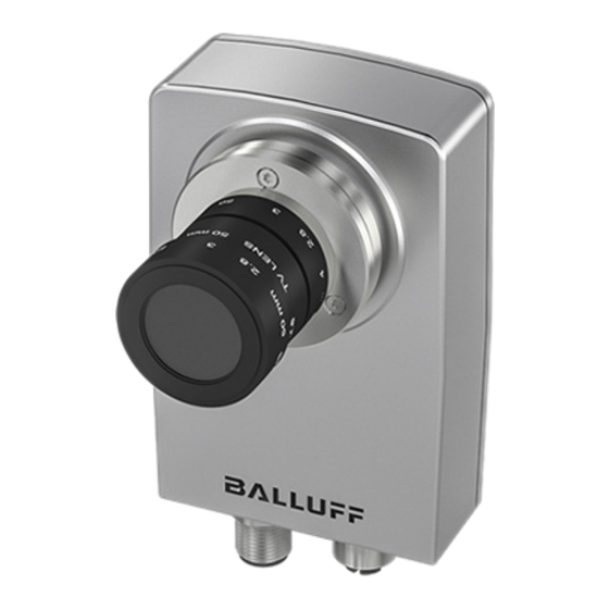
SMARTCAMERA Lite 3 Produktbeschreibung Die Balluff SMARTCAMERA BVS SL ist eine Kamera zur Aufnahme und Analyse von Schwarzweiß- und Farbbildern. Einsatzbereiche sind optische Identifikationen von Codes und Klarschrift, Inspektionen zur Qualitätssicherung und die Vermessung von Objekten. Die Kamera kann zudem in Roboterumgebungen eingesetzt werden. -
Seite 14: Lieferumfang
VS-023-1-03 (BAM039R) verwendet werden. Folgende Zubehörgruppen runden das Balluff-Angebot ab: • C-Mount-Objektive (BAM LS-VS-004-C2/3-xx14-2) • Aufschraubfilter (BAM OF-VS-002-xx-yy) • Beleuchtungen (BAE LX) • Touchpanel-PC (BAE-PD-VS-011-01) • Montagezubehör • Verbindungskabel (BCC) • Netzgeräte HINWEIS Weitere Informationen zu lieferbarer Software und Zubehör siehe www.balluff.com. -
Seite 15: Montage
Die Verschraubungen an der Rückwand haben ein M4-Gewinde. Die maximale Einschraubtiefe beträgt 4.5 mm. Das maximale Anzugsdrehmoment ist 2 Nm. WARNUNG Die SMARTCAMERA und Zubehör muss sicher befestigt sein. Verwenden Sie für die Mon- tage nur Material, welches ausreichend dimensioniert ist und eine sichere Befestigung ge- währleistet. www.balluff.com... -
Seite 16: Produktspezifikation
BVS SL-_1280Z00-07-000 SMARTCAMERA Lite Produktspezifikation 3.4.1 Bildsensor Modellvariante Monochrom (CMOS) Farbe (CMOS) Auflösung 1280 × 1024 Max. Framerate [Hz] Verschlusstyp Global Shutter Sensorgröße 1/1.8" Pixelgröße [µm] 5,3 x 5,3 Spektrale Empfindlichkeit Ein Global-Shutter-Sensor wird nicht zeilen- oder spaltenweise ausgelesen, sondern in einem Zugriff. Dadurch werden Verzerrungen bei bewegten Motiven (Rolling-Shutter-Effekt) ausgeschlossen. -
Seite 17: Betriebsbedingungen
WARNUNG Die SMARTCAMERA und angeschlossenes Zubehör darf nur mit begrenzter Energie ver- sorgt werden, entsprechend UL 61010-1 Third Edition, Sub. Clauses 9.4 oder LPS entspre- chend UL 60950-1 oder Class 2 entsprechend UL 1310 oder UL 1585. www.balluff.com... -
Seite 18: Power I/O
BVS SL-_1280Z00-07-000 SMARTCAMERA Lite 3.5.1 Power I/O Stecker M12, 5-polig, A-kodiert Pin Signal Funktion Pegel und Stromaufnahme / Ausgangs- strom +24 V Versorgungsspannung 360 mA / 12 V bzw. 180 mA / 24 V Masse RS232RX Eingang RS232 TxData Standard- -3 V bis -15 V / +3 V bis 15 V pegel RS232TX... -
Seite 19: Lan (Gigabit Ethernet)
Die LAN-Schnittstelle erfüllt den Ethernet-Standard nach IEEE 802.3-2008 (bis 1 Gigabit). Über diese Netzwerkverbin- dung wird die Weboberfläche BVS Cockpit zur Konfiguration aufgerufen. Zusätzlich ist ein Kommunikationskanal verfüg- bar, um die Bildauswertung zu steuern und die generierten Ergebniswerte abzurufen. www.balluff.com... -
Seite 20: Anzeigeelemente
BVS SL-_1280Z00-07-000 SMARTCAMERA Lite Anzeigeelemente Die Betriebszustände werden über LEDs angezeigt. Die Anzeigeelemente verteilen sich auf die Unterseite der SMART- CAMERA. 3.6.1 Anzeigen an den Steckverbindern 3.6.2 PWR (Power) Farbe Bedeutung Grün Strom ist an. Grün blinkend FPGA wird geladen. Sobald Software läuft: Software ist im Konfigurationsmodus. -
Seite 21: Erste Schritte
über Pin 1 an eine Stromquelle mit 12 V (360 mA) oder 24 V (180 mA) und Masse an Pin 2. Die SMARTCAMERA startet nun und ist nach ca. 30 Sekunden einsatzbereit. Die SMARTCAMERA öffnet beim Start das zuletzt geöffnete Inspektionsprogramm und ist im selben Prozesszustand wie beim Ausschalten. www.balluff.com... -
Seite 22: Schritt 3: Öffnen Der Weboberfläche Bvs Cockpit
HINWEIS Weitere Informationen zur Konfigurationsoberfläche BVS Cockpit finden Sie im Software- Handbuch (Handbuch BVS Cockpit) auf der Balluff Website und auf der SMARTCAMERA. Falls es bereits eine andere SMARTCAMERA im Netzwerk gibt, so können Sie sich auch mit dieser SMARTCAMERA verbinden und über die Oberfläche auf jede andere SMART-... -
Seite 23: Inbetriebnahme
PC. Auf anderen Systemen muss der Prozess angepasst werden. Um die Kamera zu aktualisieren, führen Sie die folgenden Schritte durch: Laden Sie die neueste Update-Datei über die Website von Balluff (https://www.balluff.com) herunter und speichern Sie diese lokal auf Ihrem Rechner. -
Seite 24: Netzwerk-Topologien
BVS SL-_1280Z00-07-000 SMARTCAMERA Lite Netzwerk-Topologien Zur Inbetriebnahme der SMARTCAMERA wird diese zunächst in das Netzwerkumfeld integriert. Die verschiedenen Möglichkeiten werden in den folgenden Beispielen beschrieben. Ein großer Teil der Anwendungsfälle kann dadurch ab- gedeckt werden. Zum Betrieb der SMARTCAMERA muss in jedem Fall die Versorgungsspannung über den Power-An- schluss zur Verfügung gestellt werden. -
Seite 25: Systemeinstellungen
BVS SL-_1280Z00-07-000 SMARTCAMERA Lite Systemeinstellungen Im Folgenden werden Systemeinstellungen beschrieben. Sie werden über die Auswahl Systemeinstellungen im System- menü erreicht. Das Systemmenü befindet sich im oberen Teil der Bedienoberfläche. Es besteht aus folgenden Menüpunkten: Menüpunkt Bedeutung Benutzer-Anmeldung Kameraauswahl Systemeinstellung Hilfesystem www.balluff.com... -
Seite 26: Auswählen Der Kommunikationsschnittstelle Für Die Prozessdaten
BVS SL-_1280Z00-07-000 SMARTCAMERA Lite Auswählen der Kommunikationsschnittstelle für die Prozessdaten Der Austausch der Prozessdaten (Ergebnisse der Bildauswertung, Steuerung der Bildaufnahme, …) wird über die LAN- Schnittstelle vorgenommen und seriell oder mittels UDP- oder TCP-Pakete übertragen. → Die entsprechende Protokolle sind im separaten Software-Handbuch ("BVS Cockpit Handbuch") unter "Anbindung an das Kundensteuerungssystem →... -
Seite 27: Netzwerkeinstellungen / Lan-Schnittstelle
Wenn nur vom gleichen Subnetz auf die Kamera zugegriffen werden soll, ist die Ein- gabe optional. Port Auf welchem Port das Webinterface der SMARTCAMERA angesprochen werden kann. Stan- dard ist Port 80. Avahi/Bonjour ver- Bestimmt, ob die Kamera sich über ihren Namen im Netzwerk bei anderen Kameras meldet. wenden www.balluff.com... -
Seite 28: Digitale I/O-Schnittstelle
BVS SL-_1280Z00-07-000 SMARTCAMERA Lite Digitale I/O-Schnittstelle Die SMARTCAMERA stellt acht interne I/O-Signale zur Verfügung. Digitale Eingänge und Ausgänge werden in den Systemeinstellungen im Register Digitale Ein-/Ausgänge konfiguriert. Ein- Beschreibung stel- lung I/O- Definiert, ob es sich um einen Eingang, einen Ausgang, die Blitzleitung oder die Triggerleitung handelt. Ein- gänge können über das Tool "Eingänge lesen"... -
Seite 29: Anhang
Internetprotokolls (TCP/Version 4) Stellen Sie IP-Adresse auf automatisch beziehen Stellen Sie im Reiter Alternative Konfiguration die IP-Adresse ebenfalls auf automa- tisch Schließen Sie die Fenster und starten Sie den Rechner neu. Führen Sie anschließend erneut den zuvor beschriebenen Weg aus www.balluff.com... - Seite 30 BVS SL-_1280Z00-07-000 SMARTCAMERA Lite Keine Verbin- Falsche Konfiguration des Sollten Sie mit dem zuvor beschriebenen Weg noch immer dung zu Kamera Rechners - keine Verbindung zur Kamera herstellen können, kann es da- möglich ran liegen, dass Ihr PC/Laptop den NetBIOS-Namen (http://sl- NetBIOS-Name (http://sl-...
- Seite 31 Fehlercode Falls kein Eingabefenster erscheinen sollte, können Sie in 0x80070035 Windows über folgenden Kommandozeilen-Befehl den Zugriff auf die freigegebenen Ordner erhalten: cmdkey.exe /add:sl-nnnnnnnnnde /U:ex- pert /P:expert Ersetzen Sie die Daten mit den Werten Ihrer Smart Camera. www.balluff.com...
-
Seite 32: Typenschlüssel
BVS SL-_1280Z00-07-000 SMARTCAMERA Lite Typenschlüssel Balluff Vision Solutions SMARTCAMERA Lite Funktionstyp M: Monochromer Sensor C: Farbsensor 9-12 Auflösung 1280: 1280 x 1024 Pixel Beleuchtung Z: Keine integrierte Beleuchtung 14-15 Optik 00: C-Mount-Objektive 17-18 Schnittstelle 07: IO-Variante 20-22 Varianten 000: Alle Werkzeuge... -
Seite 33: Zubehör
Befestigung für Wechselplatte Verbindungskabel BCC0HZK BCC M418-E818-8X0-723-PS58N9-020 GigE Kabel RJ45, M12, 2 m BCC0KE6 BCC M41C-0000-1A-169-PS0C25-020-C009 Power-I/O-Kabel, M12, 12-polig, A-codiert, 2 m HINWEIS Weiteres Zubehör zur BVS SL-… wie Objektive, Filter, Beleuchtungen oder Verbindungska- bel finden Sie unter www.balluff.com. www.balluff.com... - Seite 35 BVS SL- _ 1280Z00-07-0 _ _...