Herunterladen Inhalt Inhalt Diese Seite drucken
REMEHA SCB-10 Betriebs Und Installationsanleitung
Vorschau ausblenden Andere Handbücher für SCB-10:
Inhaltsverzeichnis

Werbung

Verfügbare Sprachen
  • DE

Verfügbare Sprachen

  • DEUTSCH, seite 194
User and Installation Manual
en
Notice d'installation et d'utilisation
fr
Betriebs- und Installationsanleitung
de
Manuale uso e installazione
it
Manual de usuario y de instalación
es
Gebruikers- en installatiehandleiding
nl
SCB-10

Werbung

Inhaltsverzeichnis
loading

Inhaltszusammenfassung für REMEHA SCB-10

  • Seite 1 User and Installation Manual Notice d’installation et d’utilisation Betriebs- und Installationsanleitung Manuale uso e installazione Manual de usuario y de instalación Gebruikers- en installatiehandleiding SCB-10...
  • Seite 2: Inhaltsverzeichnis

    Connection options for the expansion PCB - SCB-10 ....... . .
  • Seite 3: About This Manual

    1 About this manual About this manual Symbols used in the manual This manual contains special instructions, marked with specific symbols. Please pay extra attention when these symbols are used. Caution Risk of material damage. Important Please note: important information. Reference to other manuals or pages in this manual.
  • Seite 4: Description Of The Product

    Connection options for the expansion PCB - SCB-10 Different heating zones can be connected to the SCB-10 PCB. control of 2 (mixing) zones fitted on connector X15 control of a third (mixing) zone via an PCB (= accessory) fitted on connector X8 7747028 - v.01 - 25112019...
  • Seite 5 (DHW) zone cascade layout (add sensor on sensor system 1 or 2) Important If the boiler is fitted with the SCB-10 PCB, then this is automatically recognised by the automatic control unit of the boiler.
  • Seite 6: Identification Number

    Rotary dial for identification number There is a rotary dial on the PCB of the following products: SCB-10 The rotary dial can be used to select an identification number for the PCB. If multiple PCBs with a rotary dial are in use, each PCB with a rotary dial can have a unique number for identification.
  • Seite 7: Before Installation

    10 = DHW Layered 11 = DHW Internal tank (1) The number refers to the circuit number which can be set with the rotary dial on the SCB-10. (2) With AD249 option. (3) The last number of the parameter is related to the zone. The code can be used to identify the parameter settings in the connection examples.
  • Seite 8: Setting The 0-10 Volt Input Function Of Scb-10

    Setting to manage domestic hot water for boilers with internal tank. Setting the 0-10 Volt input function of SCB-10 There are three options for the 0-10 Volt input control of the SCB-10 print: Disable the input function. The input is temperature based.
  • Seite 9: Cascade Control

    3 Before installation Tab.6 Control based on heat output Input signal (V) Heat output (%) Description 0–2.0 Boiler off 2.0–2.2 Heat demand 2.0–10 0–100 Desired heat output Cascade control With the HMI T-control mounted in the master boiler it is possible to manage up to 7 boilers equipped with the HMI S-control in cascade.
  • Seite 10: Connecting Diagrams

    3 Before installation Connecting diagrams 3.4.1 Symbols used Tab.7 Explanation of symbols in the hydraulics flow diagram Symbol Explanation Return pipe Flow pipe Mixing valve Pump Domestic hot water Make contact Outdoor temperature sensor Sensor Safety thermostat Room thermostat Plate heat exchanger Safety group Low-loss header Instant boiler...
  • Seite 11 3 Before installation Symbol Explanation Shower Heating zone Underfloor heating Underfloor heating manifold Hot-air heater Swimming pool (1) Fitted in domestic hot water storage tank. 7747028 - v.01 - 25112019...
  • Seite 12: Connection Example 1

    RU.A S.SYST.1 S.SYST.2 S.DHW S.DEP.C S.DEP.B S.DEP.A +TA- AD-4100046-01 A Boiler C Domestic Hot water zone-DHW (1 sensor ) B Direct zone-CircA Important All the factory settings of the SCB-10 are adequate for this connection. 7747028 - v.01 - 25112019...
  • Seite 13: Connection Example 2

    RU.B RU.A S.SYST.1 S.SYST.2 S.DHW S.DEP.C S.DEP.B S.DEP.A +TA- AD-4100047-01 A Boiler C Mixing zone - CircB B Direct zone - CircA Important All the factory settings of the SCB-10 are adequate for this connection. 7747028 - v.01 - 25112019...
  • Seite 14: Connection Example 3

    S.SYST.1 S.SYST.2 S.DHW S.DEP.C S.DEP.B S.DEP.A +TA- AD-4100048-01 A Boiler C DHW zone - DHWA (1 sensor) B Mixing zone - CircB1 Important All the factory settings of the SCB-10 are adequate for this connection. 7747028 - v.01 - 25112019...
  • Seite 15: Connection Example 4

    3 Before installation 3.4.5 Connection example 4 Fig.12 1 boiler + 1 direct zone + 1 mixing zone + domestic hot water (DHW) zone AD-4100037-01 L-BUS CB-01 SCB-10 S-BUS Pump 0-10 On/off Tout 0-10V S out RU.C RU.B RU.A S.SYST.1 S.SYST.2 S.DHW...
  • Seite 16 3 Before installation Tab.8 On > > Installation Setup > SCB-10 > DHWA > Parameters, counters, signals > Parameters Code Display text Description Range Setting CP022 Zone Function Functionality of the zone 0 = Disable 1 = Direct 2 = Mixing Circuit...
  • Seite 17: Connection Example 5

    E Mixing zone - CircC C Mixing zone - CircA F DHW zone - DHWA (1 sensor) Tab.10 On > > Installation Setup > SCB-10 > Pass.buff.tank 2sens > Parameters, counters, signals > Parameters Code Display text Description Range Setting...
  • Seite 18 3 Before installation Tab.11 On > > Installation Setup > SCB-10 > CIRCA> Parameters, counters, signals > Parameters Code Display text Description Range Setting CP000 MaxZoneTFlowSetpoint Maximum Flow Temperature setpoint 7 °C - 100 °C zone CP010 Tflow setpoint zone Zone flow temperature setpoint, used 7 °C - 100 °C...
  • Seite 19: Connection Example 6

    3 Before installation 3.4.7 Connection example 6 Fig.14 1 boiler + 1 mixing zone + 1 direct zone + swimming pool zone + domestic hot water (DHW) zone AD-4100039-01 L-BUS CB-01 SCB-10 S-BUS Pump 0-10 On/off Tout 0-10V S out RU.C...
  • Seite 20 9 = ProcessHeat 10 = DHW Layered 11 = DHW Internal tank 31 = DHW FWS EXT Tab.13 On > > Installation Setup > SCB-10 > CIRCC > Parameters, counters, signals > Parameters Code Display text Description Range Setting CP023...
  • Seite 21 3 Before installation Tab.15 On > > Installation Setup > SCB-10 > AUX > Parameters, counters, signals > Parameters Code Display text Description Range Setting CP024 Zone Function Functionality of the zone 0 = Disable 1 = Direct 2 = Mixing Circuit...
  • Seite 22: Connection Example 10

    3 Before installation 3.4.8 Connection example 10 Fig.15 1 boiler (A) + low-loss header + 2 mix groups (B, C) + boiler group (D) AD-4100040-01 L-BUS CB-01 SCB-10 S-BUS Pump 0-10 On/off Tout 0-10V S out RU.C RU.B RU.A S.SYST.1 S.SYST.2 S.DHW...
  • Seite 23 7 Electrical DHW 8 Time Program 9 ProcessHeat 10 DHW Layered 11 DHW Internal tank 31 DHW FWS EXT Tab.17 > Installation Setup > SCB-10 > DHWA > Parameters, counters, signals > Parameters Code Display text Description Range Adjustment CP022...
  • Seite 24: Connection Example 11

    E Mixing zone - CircC (underfloor heating) C Mixing zone - CircA F DHW zone - DHWA (layered calorifier - 2 sensors) Tab.19 On > > Installation Setup >SCB-10 > CIRCA> Parameters, counters, signals > Parameters Code Display text Description Range...
  • Seite 25 9 = ProcessHeat 10 = DHW Layered 11 = DHW Internal tank 31 = DHW FWS EXT Tab.22 On > > Installation Setup >SCB-10 > Cascade management B > Parameters, counters, signals > Parameters Code Display text Description Range Setting...
  • Seite 26 3 Before installation Tab.23 On > > Installation Setup > SCB-10 > Analogue input > Parameters, counters, signals > Adv. Parameters Code Display text Description Range Setting EP036 Sensor input config Sets the general configuration of the 0 = Disabled...
  • Seite 27: Connection Example 12

    3 Before installation 3.4.10 Connection example 12 Fig.17 1 boiler + low-loss header + 1 direct zone + 1 mixing zone + domestic hot water (DHW) zone AD-4100042-01 L-BUS CB-01 SCB-10 S-BUS Pump 0-10 On/off Tout 0-10V S out RU.C RU.B...
  • Seite 28 8 = Time Program 9 = ProcessHeat 10 = DHW Layered 11 = DHW Internal tank 31 = DHW FWS EXT Tab.26 Installation Setup > SCB-10 > Cascade management B > Parameters, counters, signals > Parameters Code Display text Description Range Setting...
  • Seite 29: Connection Example 14

    B Boiler (slave) A-B S-BUS cable (comes with 2 resistors; one on C Low-loss header connector X5 on the SCB-10 PCB and one on D Mixing zone - CircC connector X10 on the CB-01 PCB from boiler B) 7747028 - v.01 - 25112019...
  • Seite 30 8 = Time Program 9 = ProcessHeat 10 = DHW Layered 11 = DHW Internal tank 31 = DHW FWS EXT Tab.30 Installation Setup > SCB-10 > Cascade management B > Parameters, counters, signals > Parameters Code Display text Description Range Setting...
  • Seite 31: Connection Example 16

    C Low-loss header A-B S-BUS cable (comes with 2 resistors; one on D Mixing zone - CircA connector X5 on the SCB-10 PCB and one on E Mixing zone - CircB connector X10 on the CB-01 PCB from boiler B)
  • Seite 32 8 = Time Program 9 = ProcessHeat 10 = DHW Layered 11 = DHW Internal tank 31 = DHW FWS EXT Tab.35 Installation Setup > SCB-10 > Cascade management B > Parameters, counters, signals > Parameters Code Display text Description Range Setting...
  • Seite 33 3 Before installation Tab.36 Installation Setup > SCB-10 > Analogue input > Parameters, counters, signals > Adv. Parameters Code Display text Description Range Setting EP036 Sensor input config Sets the general configuration of the 0 = Disabled sensor input 1 = DHW tank...
  • Seite 34: Installation

    4 Installation Installation Electrical connections 4.1.1 Connecting a domestic hot water (DHW) pump Connecting a domestic hot water (DHW) pump. The maximum power consumption is 300 VA. Fig.20 DHW pump connector Connect the pump as follows: Earth N Neutral L Phase AD-4000123-01 4.1.2 Connecting a mixing valve...
  • Seite 35: Connecting Room Thermostats Per Zone

    Connecting room thermostats per zone Fig.25 R-bus connectors The SCB-10 is fitted with three R-Bus connectors. They can be used to connect room thermostats per zone. The R-bus connectors are related to the other zone-specific connectors on the SCB-10.The R-Bus connector...
  • Seite 36: Settings

    User > Submenu Basic installer > Installation Setup > SCB-10 > Submenu > Parameters, counters, signals > Parameters (1) See the column "Submenu" in the following table for the correct navigation. The parameters are grouped in specific functionalities. (2) See the column "Submenu" in the following table for the correct navigation. The parameters are grouped in specific functionalities.
  • Seite 37 5 Settings Code Display text Description Range Submenu Submenu Default setting AP089 Installer name Name of the installer Mandatory bus master AP090 Installer phone Telephone number of the installer Mandatory bus master CP010 Tflow setpoint Zone flow temperature setpoint, 7 °C - 100 °C CIRCA 1 CP011 zone...
  • Seite 38 5 Settings Code Display text Description Range Submenu Submenu Default setting CP158 RoomCoolTem Setpoint of the room cooling 20 °C - 30 °C CIRCC 1 CP159 pSetpoint temperature of the zone CP160 CP161 CP162 CP163 CP164 RoomCoolTem Setpoint of the room cooling 20 °C - 30 °C AUX 1 CP165...
  • Seite 39 Installer > Submenu Installer > Installation Setup > SCB-10 > Submenu > Parameters, counters, signals > Parameters (1) See the column "Submenu" in the following table for the correct navigation. The parameters are grouped in specific functionalities. (2) See the column "Submenu" in the following table for the correct navigation. The parameters are grouped in specific functionalities.
  • Seite 40 5 Settings Code Display text Description Range Submenu Submenu Default setting AP091 Outside Sens. Type of outside sensor 0 = Auto Outdoor Source connection to be used 1 = Wired sensor temperatur 2 = Wireless sensor 3 = Internet measured 4 = None BP001 Type Buffer...
  • Seite 41 5 Settings Code Display text Description Range Submenu Submenu Default setting CP020 Zone Function Functionality of the zone 0 = Disable CIRCA 1 CP021 1 = Direct CIRCB 1 CP022 2 = Mixing Circuit DHW 1 CP023 3 = Swimming pool CIRCC 1 CP024 4 = High Temperature...
  • Seite 42 5 Settings Code Display text Description Range Submenu Submenu Default setting CP270 CoolMixTflowZ Mixing flow temperature setpoint 11 °C - 23 °C CIRCA 1 CP271 oneSet cooling of the zone CIRCB 1 CP272 DHW 1 CP273 CIRCC 1 CP274 AUX 1 CP280 FanCoolTflowZ Fan flow setpoint cooling of the...
  • Seite 43 5 Settings Code Display text Description Range Submenu Submenu Default setting CP480 ScreedStartTe Setting of the start temperature of 20 °C - 50 °C CIRCA 1 CP481 the screed drying program of the CIRCB 1 CP482 zone DHW 1 CP483 CIRCC 1 CP484 AUX 1...
  • Seite 44 5 Settings Code Display text Description Range Submenu Submenu Default setting CP700 DHW Cal Offset Offset for calorifier sensor per 0 °C - 30 °C CIRCA 1 CP701 zone zone CIRCB 1 CP702 DHW 1 CP703 CIRCC 1 CP704 AUX 1 CP710 Zone Increase primary temperature...
  • Seite 45 > Submenu > ADV Advanced installer > Installation Setup > SCB-10 > Submenu > Parameters, counters, signals > Adv. Parameters (1) See the column "Submenu" in the following table for the correct navigation. The parameters are grouped in specific functionalities.
  • Seite 46 5 Settings Tab.42 Factory settings at advanced installer level Code Display text Description Range Submenu Submenu Default setting AP111 Can line length Can line length 0 = < 3m Mandatory AP112 1 = < 80m bus master 2 = < 500m Cascade manageme nt B...
  • Seite 47: Reading Out Measured Values

    User > SCB-10 Basic installer > Installation Setup > SCB-10 > Submenu > Parameters, counters, signals > Counters (1) See the column "Submenu" in the following table for the correct navigation. The counters are grouped in specific functionalities. 7747028 - v.01 - 25112019...
  • Seite 48 5 Settings Tab.44 Counters at user / basic installer level Code Display text Description Range Subme­ AC001 Hours on mains Number of hours that the appliance has 0 Hours - 4294967294 Hours System been on mains power Function ality CC001 Zone Pump Run Numbers of pump operating hours of the 0 - 4294967294...
  • Seite 49 5 Settings Code Display text Description Range Subme­ CC003 Zone Pump Run Numbers of pump operating hours of the 0 - 4294967294 Direct Hours zone zone Mixed zone Swimmin g pool High temp. zone convecto r zone tank Electrical tank Process heat layered...
  • Seite 50 5 Settings Code Display text Description Range Subme­ CC005 Zone Pump Run Numbers of pump operating hours of the 0 - 4294967294 Direct Hours zone zone Mixed zone Swimmin g pool High temp. zone convecto r zone tank Electrical tank Process heat layered...
  • Seite 51 5 Settings Code Display text Description Range Subme­ CC011 Zone Nbr Pump Numbers of times the pump of the zone 0 - 4294967294 Direct Starts has started zone Mixed zone Swimmin g pool High temp. zone convecto r zone tank Electrical tank Process...
  • Seite 52 5 Settings Code Display text Description Range Subme­ CC013 Zone Nbr Pump Numbers of times the pump of the zone 0 - 4294967294 Direct Starts has started zone Mixed zone Swimmin g pool High temp. zone convecto r zone tank Electrical tank Process...
  • Seite 53: Scb-10 Expansion Pcb Signals

    Menu path User > SCB-10 Basic installer > Installation Setup > SCB-10 > Submenu > Parameters, counters, signals > Signals (1) See the column "Submenu" in the following table for the correct navigation. The signals are grouped in specific functionalities. Tab.46...
  • Seite 54 5 Settings Code Display text Description Range Subme­ CM033 Zone Measure of the room temperature of the 0 °C - 50 °C Direct RoomTemperature zone zone Mixed zone High temp. zone convecto r zone CM034 Zone Measure of the room temperature of the 0 °C - 50 °C Direct RoomTemperature...
  • Seite 55 5 Settings Code Display text Description Range Subme­ CM042 Zone Tflow /DHW Measure Zone Flow Temperature or DHW -10 °C - 140 °C Mixed temp temperature zone Swimmin g pool tank Electrical tank Process heat layered tank Commer cial Tank CM043 Zone Tflow /DHW Measure Zone Flow Temperature or DHW...
  • Seite 56 5 Settings Code Display text Description Range Subme­ CM060 ZonePumpSpeed Current Pump speed of zone 0 % - 100 % Direct zone Mixed zone Swimmin g pool High temp. zone convecto r zone tank Electrical tank Process heat layered tank Commer cial Tank CM061...
  • Seite 57 5 Settings Code Display text Description Range Subme­ CM062 ZonePumpSpeed Current Pump speed of zone 0 % - 100 % Direct zone Mixed zone Swimmin g pool High temp. zone convecto r zone tank Electrical tank Process heat layered tank Commer cial Tank CM063...
  • Seite 58 5 Settings Code Display text Description Range Subme­ CM064 ZonePumpSpeed Current Pump speed of zone 0 % - 100 % Direct zone Mixed zone Swimmin g pool High temp. zone convecto r zone tank Electrical tank Process heat layered tank Commer cial Tank CM070...
  • Seite 59 5 Settings Code Display text Description Range Subme­ CM071 Zone Tflow Setpoint Current Flow temperature setpoint of zone 0 °C - 150 °C Direct zone Mixed zone Swimmin g pool High temp. zone convecto r zone tank Electrical tank Process heat layered tank...
  • Seite 60 5 Settings Code Display text Description Range Subme­ CM073 Zone Tflow Setpoint Current Flow temperature setpoint of zone 0 °C - 150 °C Direct zone Mixed zone Swimmin g pool High temp. zone convecto r zone tank Electrical tank Process heat layered tank...
  • Seite 61 5 Settings Code Display text Description Range Subme­ CM120 ZoneCurrentMode Zone Current Mode 0 = Scheduling Direct 1 = Manual zone 2 = Antifrost Mixed 3 = Temporary zone Swimmin g pool High temp. zone convecto r zone tank Electrical tank layered tank...
  • Seite 62 5 Settings Code Display text Description Range Subme­ CM122 ZoneCurrentMode Zone Current Mode 0 = Scheduling Direct 1 = Manual zone 2 = Antifrost Mixed 3 = Temporary zone Swimmin g pool High temp. zone convecto r zone tank Electrical tank layered tank...
  • Seite 63 5 Settings Code Display text Description Range Subme­ CM124 ZoneCurrentMode Zone Current Mode 0 = Scheduling Direct 1 = Manual zone 2 = Antifrost Mixed 3 = Temporary zone Swimmin g pool High temp. zone convecto r zone tank Electrical tank layered tank...
  • Seite 64 5 Settings Code Display text Description Range Subme­ CM131 ZoneCurrent activity Current activity of the zone 0 = Anti frost Direct 1 = Reduced zone 2 = Comfort Mixed 3 = Anti legionella zone Swimmin g pool High temp. zone convecto r zone tank...
  • Seite 65 5 Settings Code Display text Description Range Subme­ CM133 ZoneCurrent activity Current activity of the zone 0 = Anti frost Direct 1 = Reduced zone 2 = Comfort Mixed 3 = Anti legionella zone Swimmin g pool High temp. zone convecto r zone tank...
  • Seite 66 5 Settings Code Display text Description Range Subme­ CM190 Zone Troom Wished room temperature setpoint of the 0 °C - 50 °C Direct setpoint zone zone Mixed zone High temp. zone convecto r zone CM191 Zone Troom Wished room temperature setpoint of the 0 °C - 50 °C Direct setpoint...
  • Seite 67 5 Settings Code Display text Description Range Subme­ CM201 ZoneCurrentHeatMo Displaying current operating mode of the 0 = Standby Direct zone 1 = Heating zone 2 = Cooling Mixed zone Swimmin g pool High temp. zone convecto r zone CM202 ZoneCurrentHeatMo Displaying current operating mode of the 0 = Standby...
  • Seite 68 5 Settings Code Display text Description Range Subme­ CM211 ZoneTout temp Current outdoor temperature of the zone -70 °C - 70 °C Direct zone Mixed zone High temp. zone convecto r zone CM212 ZoneTout temp Current outdoor temperature of the zone -70 °C - 70 °C Direct zone...
  • Seite 69 Menu path Installer > SCB-10 Installer > Installation Setup > SCB-10 > Submenu > Parameters, counters, signals > Signals (1) See the column "Submenu" in the following table for the correct navigation. The signals are grouped in specific functionalities. Tab.48...
  • Seite 70 5 Settings Code Display text Description Range Subme­ CM161 Zone Mod Presense of modulating heat demand per 0 = No Direct HeatDemand zone 1 = Yes zone Mixed zone High temp. zone convecto r zone Electrical tank layered tank CM162 Zone Mod Presense of modulating heat demand per 0 = No...
  • Seite 71 5 Settings Code Display text Description Range Subme­ CM164 Zone Mod Presense of modulating heat demand per 0 = No Direct HeatDemand zone 1 = Yes zone Mixed zone High temp. zone convecto r zone Electrical tank layered tank CM290 ZoneSecSwimPoolP Status of the secondary pump used for the 0 = Off...
  • Seite 72 Advanced installer > SCB-10 Advanced installer > Installation Setup > SCB-10 > Submenu > Parameters, counters, signals > Adv. Signals (1) See the column "Submenu" in the following table for the correct navigation. The signals are grouped in specific functionalities.
  • Seite 73 5 Settings Code Display text Description Range Subme­ CM020 Zone 3WV opening Mixing valve opening status of zone 0 = No Mixed 1 = Yes zone Swimmin g pool Electrical tank CM021 Zone 3WV opening Mixing valve opening status of zone 0 = No Mixed 1 = Yes...
  • Seite 74 5 Settings Code Display text Description Range Subme­ CM050 Status Pump zone Status of the Pump of zone 0 = No Direct 1 = Yes zone Mixed zone Swimmin g pool High temp. zone convecto r zone tank Electrical tank Zone time program...
  • Seite 75 5 Settings Code Display text Description Range Subme­ CM052 Status Pump zone Status of the Pump of zone 0 = No Direct 1 = Yes zone Mixed zone Swimmin g pool High temp. zone convecto r zone tank Electrical tank Zone time program...
  • Seite 76 5 Settings Code Display text Description Range Subme­ CM054 Status Pump zone Status of the Pump of zone 0 = No Direct 1 = Yes zone Mixed zone Swimmin g pool High temp. zone convecto r zone tank Electrical tank Zone time program...
  • Seite 77 5 Settings Code Display text Description Range Subme­ CM113 ZoneTRoomUnit Room Unit temperature setpoint of zone 0 °C - 50 °C Direct setp zone Mixed zone High temp. zone convecto r zone CM114 ZoneTRoomUnit Room Unit temperature setpoint of zone 0 °C - 50 °C Direct setp...
  • Seite 78 5 Settings Code Display text Description Range Subme­ CM142 ZoneOTContr OpenTherm controller is connected to the 0 = No Direct present zone 1 = Yes zone Mixed zone Swimmin g pool High temp. zone convecto r zone Electrical tank layered tank CM143 ZoneOTContr...
  • Seite 79 5 Settings Code Display text Description Range Subme­ CM150 ZoneState State of On Off heat demand per zone 0 = No Direct Heatdemand 1 = Yes zone Mixed zone Swimmin g pool High temp. zone convecto r zone Electrical tank layered tank CM151...
  • Seite 80 5 Settings Code Display text Description Range Subme­ CM153 ZoneState State of On Off heat demand per zone 0 = No Direct Heatdemand 1 = Yes zone Mixed zone Swimmin g pool High temp. zone convecto r zone Electrical tank layered tank CM154...
  • Seite 81 5 Settings Code Display text Description Range Subme­ CM181 Zone RU present Presense of Room Unit in this zone 0 = No Direct 1 = Yes zone Mixed zone Swimmin g pool High temp. zone convecto r zone tank Electrical tank Process heat...
  • Seite 82 5 Settings Code Display text Description Range Subme­ CM183 Zone RU present Presense of Room Unit in this zone 0 = No Direct 1 = Yes zone Mixed zone Swimmin g pool High temp. zone convecto r zone tank Electrical tank Process heat...
  • Seite 83 5 Settings Code Display text Description Range Subme­ CM241 Zone Tout Outdoor temperature sensor is connected 0 = No Direct connected to the zone 1 = Yes zone Mixed zone High temp. zone convecto r zone CM242 Zone Tout Outdoor temperature sensor is connected 0 = No Direct connected...
  • Seite 84 5 Settings Code Display text Description Range Subme­ CM282 ZoneRTC Internal room temperature setpoint 0 °C - 100 °C Direct TcalcRoomStp calculated by the room temperature zone controller of the zone Mixed zone High temp. zone convecto r zone CM283 ZoneRTC Internal room temperature setpoint 0 °C - 100 °C...
  • Seite 85: Scb-10 Status And Sub-Status

    5 Settings 5.3.3 SCB-10 status and sub-status Tab.51 AM012 - Status Rang Status Explanation Standby The appliance is in standby mode. Heat Demand A heat demand is active. Burner Start The appliance starts. Burning CH The appliance is active for central heating.
  • Seite 86 5 Settings Rang Status Explanation GradLevel2PowerCtrl The modulation is set to low load due to a faster heat exchanger temperature change than gradient level 2. GradLevel3PowerCtrl The appliance is in blocking mode due to a faster heat exchanger temperature change than gradient level 1. ProtectFlamePwrCtrl The burner power is increased due to a low ionisation signal.
  • Seite 87: Troubleshooting

    6 Troubleshooting Troubleshooting Warning - SCB-10 Tab.53 Warning codes Code Display text Description Solution A00.32 TOutside Open Outside temperature sensor is either removed Outdoor temperature sensor or measures a temperature below range open: Bad connection: check the wiring and connectors...
  • Seite 88 6 Troubleshooting Code Display text Description Solution A10.34 SDhwTopZoneD Closed Domestic Hot Water tank top temperature Domestic hot water top tem­ sensor Zone DHW Closed perature sensor short-circuit­ Bad connection: check the wiring and connectors Incorrectly fitted sensor: check that the sensor has been correctly fitted Faulty sensor: replace the sensor...
  • Seite 89: Blocking - Scb-10

    Domestic hot water temper­ ature sensor is not connec­ ted correctly: connect the sensor correctly Faulty sensor: replace the sensor Blocking - SCB-10 Tab.54 Blocking codes Code Display text Description Solution H00.69...
  • Seite 90 6 Troubleshooting Code Display text Description Solution H00.74 TBufferTankMissing Buffer Tank temperature sensor was Buffer tank temperature sensor not detected: expected but not detected Buffer tank temperature sensor is not connec­ ted: Connect the sensor Buffer tank temperature sensor is not connec­ ted correctly: Connect the sensor correctly Faulty sensor: replace the sensor H00.75...
  • Seite 91 6 Troubleshooting Code Display text Description Solution H02.47 Failed Conn Funct Gr Failed Connecting Function Groups Function group not found: Carry out an auto-detect Restart the boiler Replace the CU-GH H02.48 Funct Gr Conf Fault Function Group Configuration Fault SCB not found: Carry out an auto-detect H02.49 Failed Init Node...
  • Seite 92 6 Troubleshooting Code Display text Description Solution H10.01 T Flow Zone A Closed Flow temperature sensor Zone A Flow temperature sensor zone A short-circuited: Closed Bad connection: check the wiring and connec­ tors Incorrectly fitted sensor: check that the sensor has been correctly fitted Faulty sensor: replace the sensor H10.02...
  • Seite 93 6 Troubleshooting Code Display text Description Solution H10.12 T Dhw Zone B Closed Domestic Hot Water temperature Domestic hot water temperature sensor zone B sensor Zone B Closed short-circuited: Bad connection: check the wiring and connec­ tors Incorrectly fitted sensor: check that the sensor has been correctly fitted Faulty sensor: replace the sensor When using thermostat instead of sensor: pa­...
  • Seite 94 6 Troubleshooting Code Display text Description Solution H10.22 TSwimmPoolZoneC Swimming Pool Temperature Swimming pool temperature sensor C open: Open Sensor Zone C Open Bad connection: check the wiring and connec­ tors Incorrectly fitted sensor: check that the sensor has been correctly fitted Sensor is not present.
  • Seite 95 6 Troubleshooting Code Display text Description Solution H10.38 T Dhw Zone AUX open Domestic Hot Water temperature Domestic hot water temperature sensor zone sensor Zone AUX open AUX open: Bad connection: check the wiring and connec­ tors Incorrectly fitted sensor: check that the sensor has been correctly fitted Sensor is not present.
  • Seite 96 Réglage de la fonction d'entrée 0-10 V sur la carte SCB-10 ......
  • Seite 97: Propos De Cette Notice

    1 A propos de cette notice A propos de cette notice Symboles utilisés dans la notice Cette notice comporte des instructions spéciales, indiquées par des symboles spécifiques. Veillez à accorder une attention particulière partout où ces symboles sont utilisés. Attention Risque de dégâts matériels.
  • Seite 98: Description Du Produit

    01.03 1.03 Carte d'extension SCB-10 La SCB-10 permet l'utilisation d'un ballon d'eau chaude sanitaire et de trois zones de chauffage central, et dis­ pose d'une connexion 0-10 V pour une pompe PWM ainsi que d'un contact sec pour la notification d'état.
  • Seite 99: Options De Connexion De La Carte D'extension - Scb-10

    (ECS) agencement en cascade (ajouter sonde sur système de sonde 1 ou 2) Important Lorsque la carte SCB-10 est installée sur la chaudière, elle est reconnue automatiquement par l'unité de commande de la chaudière.
  • Seite 100: Numéro D'identification

    Sélecteur rotatif du numéro La carte électronique des produits suivants comporte un sélecteur rotatif : d'identification SCB-10 Ce sélecteur rotatif sert à sélectionner un numéro d'identification pour la carte. Si plusieurs cartes électroniques dotées d'un sélecteur rotatif sont utilisées, chacune d'elles peut avoir un numéro d'identification unique.
  • Seite 101: Avant L'installation

    10 = ECS stratifiée 11 = ECS Ballon interne (1) Le numéro est celui du circuit qui peut être défini à l'aide du bouton rotatif sur le SCB-10. (2) Avec l'option AD249. (3) Le dernier numéro du paramètre est lié à la zone. Le code peut être utilisé pour identifier les réglages de paramètre dans les exemples de raccordement.
  • Seite 102: Réglage De La Fonction D'entrée 0-10 V Sur La Carte Scb-10

    Réglage permettant de gérer l'eau chaude domestique pour les chaudières avec ballon interne. Réglage de la fonction d'entrée 0-10 V sur la carte SCB-10 Il existe trois options pour la commande de l'entrée 0-10 Volt sur la carte SCB-10 : désactivation de la fonction d'entrée ;...
  • Seite 103: Modulation Analogique De La Puissance

    3 Avant l'installation 3.2.2 Modulation analogique de la puissance Le signal 0-10 V module la puissance de la chaudière. Cette modulation se fait en fonction de la puissance calorifique. La puissance minimale est liée au taux de modulation de la chaudière. La puissance varie entre les valeurs minimale et maximale sur la base de la valeur déterminée par le régulateur.
  • Seite 104: Schémas De Raccordement

    3 Avant l'installation Fig.41 Mode de fonctionnement en 1 Toutes les chaudières commencent à fonctionner lorsque la cascade parallèle température du système est inférieure de 3 °C à la consigne. 2 La première chaudière s'arrête de fonctionner lorsque la température du système est supérieure de 3 °C à la consigne. 3 Après 4 minutes, la deuxième chaudière s'arrête de fonctionner si ΔT <...
  • Seite 105 3 Avant l'installation Icône Explication Bouteille de découplage Chaudière instantanée Raccordement du circuit de chauffage primaire Capteur solaire Ballon d’eau chaude sanitaire Anode titane Résistance électrique Douche Zone de chauffage Plancher chauffant Collecteur plancher chauffant Système de chauffage à air chaud Piscine (1) Installée dans le ballon d’eau chaude sanitaire 7747028 - v.01 - 25112019...
  • Seite 106: Exemple De Raccordement 1

    S.DHW S.DEP.C S.DEP.B S.DEP.A +TA- AD-4100046-01 A Chaudière C Zone d'eau chaude sanitaire - ECS (1 sonde) B Zone directe - CircA Important Tous les réglages d'usine de la carte SCB-10 conviennent pour ce raccordement. 7747028 - v.01 - 25112019...
  • Seite 107: Exemple De Raccordement 2

    RU.A S.SYST.1 S.SYST.2 S.DHW S.DEP.C S.DEP.B S.DEP.A +TA- AD-4100047-01 A Chaudière C Zone mélangée - CircB B Zone directe - CircA Important Tous les réglages d'usine de la carte SCB-10 sont appropriés pour ce raccordement. 7747028 - v.01 - 25112019...
  • Seite 108: Exemple De Raccordement 3

    S.SYST.1 S.SYST.2 S.DHW S.DEP.C S.DEP.B S.DEP.A +TA- AD-4100048-01 A Chaudière C Zone ECS - DHWA (1 sonde) B Zone mélangée - CircB1 Important Tous les réglages d'usine de la carte SCB-10 conviennent pour ce raccordement. 7747028 - v.01 - 25112019...
  • Seite 109: Exemple De Raccordement 4

    3 Avant l'installation 3.4.5 Exemple de raccordement 4 Fig.45 1 chaudière + 1 circuit direct + 1 circuit avec vanne mélangeuse + circuit d'eau chaude sanitaire (ECS) AD-4100037-01 L-BUS CB-01 SCB-10 S-BUS Pump 0-10 On/off Tout 0-10V S out RU.C RU.B...
  • Seite 110 3 Avant l'installation Tab.62 Marche > > Configuration de l'installation > SCB-10 > DHWA > Paramètres, compteurs et signaux > Paramètres Code Texte affiché Désignation Plage Réglage CP022 Fonction du circuit Fonctionnalité du circuit 0 = Désactivé 1 = Direct 2 = Circuit mélangé...
  • Seite 111: Exemple De Raccordement 5

    C Circuit avec vanne mélangeuse - CircA D Circuit avec vanne mélangeuse - CircB (plancher chauffant) Tab.64 Marche > > Configuration de l'installation > SCB-10 > Ballon tampon2sondes > Paramètres, compteurs et signaux > Paramètres Code Texte affiché Désignation Plage Réglage...
  • Seite 112 3 Avant l'installation Tab.65 Marche > > Configuration de l'installation > SCB-10 > CIRCA> Paramètres, compteurs et signaux > Paramètres Code Texte affiché Désignation Plage Réglage CP000 Max Cons Tdep Circ Consigne maximum de la température 7 °C - 100 °C départ du circuit...
  • Seite 113: Exemple De Raccordement 6

    3.4.7 Exemple de raccordement 6 Fig.47 1 chaudière + 1 circuit avec vanne mélangeuse + 1 circuit direct + circuit de piscine + circuit d'eau chaude sanitaire (ECS) AD-4100039-01 L-BUS CB-01 SCB-10 S-BUS Pump 0-10 On/off Tout 0-10V S out RU.C...
  • Seite 114 9 = Chauffage industriel 10 = ECS stratifiée 11 = ECS Ballon interne 31 = DHW FWS EXT Tab.67 Marche > > Configuration de l'installation > SCB-10 > CIRCC > Paramètres, compteurs et signaux > Paramètres Code Texte affiché Désignation Plage Réglage...
  • Seite 115 3 Avant l'installation Tab.69 Marche > > Configuration de l'installation > SCB-10 > AUX > Paramètres, compteurs et signaux > Paramètres Code Texte affiché Désignation Plage Réglage CP024 Fonction du circuit Fonctionnalité du circuit 0 = Désactivé 1 = Direct 2 = Circuit mélangé...
  • Seite 116: Exemple De Raccordement 10

    3 Avant l'installation 3.4.8 Exemple de raccordement 10 Fig.48 1 chaudière (A) + bouteille de découplage + 2 circuits avec vanne mélangeuse (B, C) + circuit ballon (D) AD-4100040-01 L-BUS CB-01 SCB-10 S-BUS Pump 0-10 On/off Tout 0-10V S out RU.C...
  • Seite 117 8 Programme horaire 9 Chauffage industriel 10 ECS stratifiée 11 ECS Ballon interne 31 DHW FWS EXT Tab.71 > Configuration de l'installation > SCB-10 > DHWA > Paramètres, compteurs et signaux > Paramètres Code Texte affiché Désignation Plage Ajustement CP022 Fonction du circuit Fonctionnalité...
  • Seite 118: Exemple De Raccordement 11

    C Circuit avec vanne mélangeuse - CircA F Circuit d'ECS - DHWA (ballon stratifié - 2 sondes) D Circuit avec vanne mélangeuse - CircB Tab.73 Marche > > Configuration de l'installation >SCB-10 > CIRCA> Paramètres, compteurs et signaux > Paramètres Code Texte affiché Désignation Plage Réglage...
  • Seite 119 Pente du circuit Pente de la Courbe de Température de 0 - 4 chauffe du circuit Tab.74 Marche > > Configuration de l'installation > SCB-10 > DHWA > Paramètres, compteurs et signaux > Paramètres Unité de co­ Texte affiché Désignation Plage Réglage...
  • Seite 120 3 Avant l'installation Tab.77 Marche > > Configuration de l'installation > SCB-10 > Entrée analogique > Paramètres, compteurs et signaux > Para. Avancés Code Texte affiché Désignation Plage Réglage EP036 Config. entrée sonde Configuration de l'entrée sonde 0 = Désactivé...
  • Seite 121: Exemple De Raccordement 12

    3.4.10 Exemple de raccordement 12 Fig.50 1 chaudière + bouteille de découplage + 1 circuit direct + 1 circuit avec vanne mélangeuse + circuit d'eau chaude sanitaire (ECS) AD-4100042-01 L-BUS CB-01 SCB-10 S-BUS Pump 0-10 On/off Tout 0-10V S out RU.C...
  • Seite 122 9 = Chauffage industriel 10 = ECS stratifiée 11 = ECS Ballon interne 31 = DHW FWS EXT Tab.80 Configuration de l'installation > SCB-10 > Gestion product. B > Paramètres, compteurs et signaux > Paramètres Code Texte affiché Désignation Plage Réglage...
  • Seite 123: Exemple De Raccordement 14

    A Chaudière (maître) A-B Câble S-BUS (livré avec 2 résistances ; une sur le B Chaudière (esclave) connecteur X5 de la carte SCB-10 et une sur le C Bouteille de découplage connecteur X10 de la carte CB-01 depuis la D Circuit avec vanne mélangeuse - CircC chaudière B)
  • Seite 124 9 = Chauffage industriel 10 = ECS stratifiée 11 = ECS Ballon interne 31 = DHW FWS EXT Tab.84 Configuration de l'installation > SCB-10 > Gestion product. B > Paramètres, compteurs et signaux > Paramètres Code Texte affiché Désignation Plage Réglage...
  • Seite 125: Exemple De Raccordement 16

    3 Avant l'installation 3.4.12 Exemple de raccordement 16 Fig.52 Cascade de 2 chaudières + bouteille de découplage + 3 circuits avec vanne mélangeuse + circuit d'eau chaude sanitaire (ECS) AD-4100044-01 L-BUS CB-01 SCB-10 S-BUS Pump 0-10 On/off Tout 0-10V S out RU.C RU.B...
  • Seite 126 31 = DHW FWS EXT CP230 Pente du circuit Pente de la Courbe de Température de 0 – 4 chauffe du circuit Tab.87 Configuration de l'installation > SCB-10 > DHWA > Paramètres, compteurs et signaux > Paramètres Code Texte affiché Désignation Plage Réglage CP022 Fonction du circuit Fonctionnalité...
  • Seite 127 3 Avant l'installation Tab.89 Configuration de l'installation > SCB-10 > Gestion product. B > Paramètres, compteurs et signaux > Paramètres Code Texte affiché Désignation Plage Réglage AP083 Maitre S-BUS Activé le maitre sur le S-BUS pour les 0 = Non...
  • Seite 128: Installation

    4 Installation Installation Raccordements électriques 4.1.1 Raccordement d'une pompe d’eau chaude sanitaire (ECS) Raccordement d'une pompe d’eau chaude sanitaire (ECS). La consommation électrique maximale est de 300 VA. Fig.53 Connecteur de pompe ECS Brancher la pompe comme suit : Terre N Neutre L Phase AD-4000123-01...
  • Seite 129: Raccordement Des Thermostats D'ambiance Par Zone

    Le SCB-10 est équipé de trois connecteurs R-Bus. Ils peuvent être utilisés pour raccorder des thermostats d'ambiance par zone. Les connecteurs R- bus sont reliés aux autres connecteurs dédiés à une zone sur le SCB-10. Le connecteur R-Bus accepte les types suivants :...
  • Seite 130: Réglages

    Utilisateur > Sous-menu Installateur de base > Configuration de l'installation > SCB-10 > Sous-menu > Paramètres, compteurs et signaux > Paramètres (1) Voir la colonne « Sous-menu » dans le tableau suivant pour la navigation appropriée. Les paramètres sont regroupés en fonctionnalités spécifiques.
  • Seite 131 5 Réglages Code Texte affiché Description Plage Sous-menu Sous-menu Régla­ ge par défaut AP081 Nom court Nom court de l'appareil System Functionalit AP089 Nom de l'installateur Bus maître installateur oblig. AP090 Tél. installateur Numéro de téléphone de Bus maître l'installateur oblig.
  • Seite 132 5 Réglages Code Texte affiché Description Plage Sous-menu Sous-menu Régla­ ge par défaut CP158 ConsAmb Circ Consigne ambiance du circuit 20 °C - 30 °C CIRCC 1 CP159 Rafr rafraîchissement CP160 CP161 CP162 CP163 CP164 ConsAmb Circ Consigne ambiance du circuit 20 °C - 30 °C AUX 1 CP165...
  • Seite 133 Installateur > Sous-menu Installateur > Configuration de l'installation > SCB-10 > Sous-menu > Paramètres, compteurs et signaux > Paramètres (1) Voir la colonne « Sous-menu » dans le tableau suivant pour la navigation appropriée. Les paramètres sont regroupés en fonctionnalités spécifiques.
  • Seite 134 5 Réglages Code Texte affiché Description Plage Sous-menu Sous-menu Régla­ ge par défaut AP091 Source sonde Type de connexion de sonde 0 = Auto Temp. ext. extérieure à utiliser 1 = Capteur filaire exterieure 2 = Capteur sans fil 3 = Mesure Internet 4 = Aucun BP001 Type Ballon...
  • Seite 135 5 Réglages Code Texte affiché Description Plage Sous-menu Sous-menu Régla­ ge par défaut CP000 Max Cons Tdep Consigne maximum de la 7 °C - 100 °C CIRCA 1 CP001 Circ température départ du circuit CIRCB 1 CP002 DHW 1 CP003 CIRCC 1 CP004 AUX 1...
  • Seite 136 5 Réglages Code Texte affiché Description Plage Sous-menu Sous-menu Régla­ ge par défaut CP230 Pente du circuit Pente de la Courbe de 0 - 4 CIRCA 1 CP231 Température de chauffe du circuit CIRCB 1 CP232 DHW 1 CP233 CIRCC 1 CP234 AUX 1 CP240...
  • Seite 137 5 Réglages Code Texte affiché Description Plage Sous-menu Sous-menu Régla­ ge par défaut CP460 Priorité ECS Choix de priorité pour ECS 0 = Totale CIRCA 1 CP461 circuit 0:TOTALE 1:RELATIVE 1 = Relative CIRCB 1 CP462 2:AUCUNE 2 = Aucun DHW 1 CP463 CIRCC 1...
  • Seite 138 5 Réglages Code Texte affiché Description Plage Sous-menu Sous-menu Régla­ ge par défaut CP650 ConsAmbRéd Consigne ambiance réduite 20 °C - 30 °C CIRCA 1 CP651 rafr circ souhaitée en mode CIRCB 1 CP652 rafraîchissement du circuit DHW 1 CP653 CIRCC 1 CP654 AUX 1...
  • Seite 139 5 Réglages Code Texte affiché Description Plage Sous-menu Sous-menu Régla­ ge par défaut EP030 Temp .mini. Consigne de température 0 °C - 100 °C Entrée 0-10V minimale pour l'entrée 0-10V 0-10V EP031 Temp .maxi. Consigne de température 0,5 °C - 100 °C Entrée 0-10V maximale pour l'entrée 0-10V...
  • Seite 140 > Sous-menu > ADV Installateur avancé > Configuration de l'installation > SCB-10 > Sous-menu > Paramètres, compteurs et signaux > Para. Avancés (1) Voir la colonne « Sous-menu » dans le tableau suivant pour la navigation appropriée. Les paramètres sont regroupés en fonctionnalités spécifiques.
  • Seite 141 5 Réglages Code Texte affiché Description Plage Sous-menu Sous-menu Régla­ ge par défaut CP730 Coef inc temp Facteur de vitesse de montée en 0 = Très lent CIRCA 1 CP731 circ température du circuit 1 = Mini CIRCB 1 CP732 2 = Lente DHW 1 CP733...
  • Seite 142: Affichage Des Valeurs Mesurées

    Utilisateur > SCB-10 Installateur de base > Configuration de l'installation > SCB-10 > Sous-menu > Paramètres, compteurs et signaux > Compteurs (1) Voir la colonne « Sous-menu » dans le tableau suivant pour la navigation appropriée. Les compteurs sont regroupés en fonctionnalités spécifiques.
  • Seite 143 5 Réglages Code Texte affiché Description Plage Sous- menu CC002 NbrHeureFctPompe Nombre d'heures de fonctionnement de la 0 - 4294967294 Circuit Circ pompe du circuit direct Zone mixte Piscine Haute températ Zone ventilo- conv. Ballon Ballon élec. Process heat Ballon ECS 2 sondes ECS BIC...
  • Seite 144 5 Réglages Code Texte affiché Description Plage Sous- menu CC004 NbrHeureFctPompe Nombre d'heures de fonctionnement de la 0 - 4294967294 Circuit Circ pompe du circuit direct Zone mixte Piscine Haute températ Zone ventilo- conv. Ballon Ballon élec. Process heat Ballon ECS 2 sondes ECS BIC...
  • Seite 145 5 Réglages Code Texte affiché Description Plage Sous- menu CC010 NbrDém PompeCirc Nombre de démarrages de la pompe du 0 - 4294967294 Circuit circuit direct Zone mixte Piscine Haute températ Zone ventilo- conv. Ballon Ballon élec. Process heat Ballon ECS 2 sondes ECS BIC commerc...
  • Seite 146 5 Réglages Code Texte affiché Description Plage Sous- menu CC012 NbrDém PompeCirc Nombre de démarrages de la pompe du 0 - 4294967294 Circuit circuit direct Zone mixte Piscine Haute températ Zone ventilo- conv. Ballon Ballon élec. Process heat Ballon ECS 2 sondes ECS BIC commerc...
  • Seite 147 5 Réglages Code Texte affiché Description Plage Sous- menu CC013 NbrDém PompeCirc Nombre de démarrages de la pompe du 0 - 4294967294 Circuit circuit direct Zone mixte Piscine Haute températ Zone ventilo- conv. Ballon Ballon élec. Process heat Ballon ECS 2 sondes ECS BIC commerc...
  • Seite 148: Signaux De La Carte D'extension Scb-10

    Utilisateur > SCB-10 Installateur de base > Configuration de l'installation > SCB-10 > Sous-menu > Paramètres, compteurs et signaux > Signaux (1) Voir la colonne « Sous-menu » dans le tableau suivant pour la navigation appropriée. Les signaux sont regroupés en fonctionnalités spécifiques.
  • Seite 149 5 Réglages Code Texte affiché Description Plage Sous- menu CM033 Mes Ambiance circ Mesure de la température ambiance du 0 °C - 50 °C Circuit circuit direct Zone mixte Haute températ Zone ventilo- conv. CM034 Mes Ambiance circ Mesure de la température ambiance du 0 °C - 50 °C Circuit circuit...
  • Seite 150 5 Réglages Code Texte affiché Description Plage Sous- menu CM042 T Départ circuit Mesure de la température de départ du -10 °C - 140 °C Zone circuit mixte Piscine Ballon Ballon élec. Process heat Ballon ECS 2 sondes commerc CM043 T Départ circuit Mesure de la température de départ du -10 °C - 140 °C...
  • Seite 151 5 Réglages Code Texte affiché Description Plage Sous- menu CM060 Vitesse Pompe circ Vitesse de la pompe du circuit 0 % - 100 % Circuit direct Zone mixte Piscine Haute températ Zone ventilo- conv. Ballon Ballon élec. Process heat Ballon ECS 2 sondes commerc...
  • Seite 152 5 Réglages Code Texte affiché Description Plage Sous- menu CM062 Vitesse Pompe circ Vitesse de la pompe du circuit 0 % - 100 % Circuit direct Zone mixte Piscine Haute températ Zone ventilo- conv. Ballon Ballon élec. Process heat Ballon ECS 2 sondes commerc...
  • Seite 153 5 Réglages Code Texte affiché Description Plage Sous- menu CM064 Vitesse Pompe circ Vitesse de la pompe du circuit 0 % - 100 % Circuit direct Zone mixte Piscine Haute températ Zone ventilo- conv. Ballon Ballon élec. Process heat Ballon ECS 2 sondes commerc...
  • Seite 154 5 Réglages Code Texte affiché Description Plage Sous- menu CM071 Cons Tdépart circuit Consigne en température du départ du 0 °C - 150 °C Circuit circuit direct Zone mixte Piscine Haute températ Zone ventilo- conv. Ballon Ballon élec. Process heat Ballon ECS 2 sondes...
  • Seite 155 5 Réglages Code Texte affiché Description Plage Sous- menu CM073 Cons Tdépart circuit Consigne en température du départ du 0 °C - 150 °C Circuit circuit direct Zone mixte Piscine Haute températ Zone ventilo- conv. Ballon Ballon élec. Process heat Ballon ECS 2 sondes...
  • Seite 156 5 Réglages Code Texte affiché Description Plage Sous- menu CM120 Mode Circuit Mode de fonctionnement du circuit 0 = Programmation Circuit 1 = Manuelle direct 2 = Anti-gel Zone 3 = Temporaire mixte Piscine Haute températ Zone ventilo- conv. Ballon Ballon élec.
  • Seite 157 5 Réglages Code Texte affiché Description Plage Sous- menu CM122 Mode Circuit Mode de fonctionnement du circuit 0 = Programmation Circuit 1 = Manuelle direct 2 = Anti-gel Zone 3 = Temporaire mixte Piscine Haute températ Zone ventilo- conv. Ballon Ballon élec.
  • Seite 158 5 Réglages Code Texte affiché Description Plage Sous- menu CM124 Mode Circuit Mode de fonctionnement du circuit 0 = Programmation Circuit 1 = Manuelle direct 2 = Anti-gel Zone 3 = Temporaire mixte Piscine Haute températ Zone ventilo- conv. Ballon Ballon élec.
  • Seite 159 5 Réglages Code Texte affiché Description Plage Sous- menu CM131 Activité actu circ Activité en cours pour le circuit 0 = Anti-gel Circuit 1 = Réduit direct 2 = Confort Zone 3 = Anti légionellose mixte Piscine Haute températ Zone ventilo- conv.
  • Seite 160 5 Réglages Code Texte affiché Description Plage Sous- menu CM133 Activité actu circ Activité en cours pour le circuit 0 = Anti-gel Circuit 1 = Réduit direct 2 = Confort Zone 3 = Anti légionellose mixte Piscine Haute températ Zone ventilo- conv.
  • Seite 161 5 Réglages Code Texte affiché Description Plage Sous- menu CM190 Cons Amb circuit Consigne de température ambiance 0 °C - 50 °C Circuit souhaitée pour le circuit direct Zone mixte Haute températ Zone ventilo- conv. CM191 Cons Amb circuit Consigne de température ambiance 0 °C - 50 °C Circuit souhaitée pour le circuit...
  • Seite 162 5 Réglages Code Texte affiché Description Plage Sous- menu CM201 ModeFct Chauff Circ Mode de fonctionnement en cours du 0 = Veille Circuit circuit 1 = Chauffage direct 2 = Rafraîchissement Zone mixte Piscine Haute températ Zone ventilo- conv. CM202 ModeFct Chauff Circ Mode de fonctionnement en cours du 0 = Veille Circuit...
  • Seite 163 5 Réglages Code Texte affiché Description Plage Sous- menu CM211 Circ Mes Mesure de la Température Extérieure du -70 °C - 70 °C Circuit TExtérieure circuit direct Zone mixte Haute températ Zone ventilo- conv. CM212 Circ Mes Mesure de la Température Extérieure du -70 °C - 70 °C Circuit TExtérieure...
  • Seite 164 Installateur > SCB-10 Installateur > Configuration de l'installation > SCB-10 > Sous-menu > Paramètres, compteurs et signaux > Signaux (1) Voir la colonne « Sous-menu » dans le tableau suivant pour la navigation appropriée. Les signaux sont regroupés en fonctionnalités spécifiques.
  • Seite 165 5 Réglages Code Texte affiché Description Plage Sous- menu CM161 DemChaufModul Etat de la demande de chauffe modulante 0 = Non Circuit Circ du circuit 1 = Oui direct Zone mixte Haute températ Zone ventilo- conv. Ballon élec. Ballon ECS 2 sondes CM162 DemChaufModul...
  • Seite 166 5 Réglages Code Texte affiché Description Plage Sous- menu CM164 DemChaufModul Etat de la demande de chauffe modulante 0 = Non Circuit Circ du circuit 1 = Oui direct Zone mixte Haute températ Zone ventilo- conv. Ballon élec. Ballon ECS 2 sondes CM290 CircPompSecondPis...
  • Seite 167 Installateur avancé > SCB-10 Installateur avancé > Configuration de l'installation > SCB-10 > Sous-menu > Paramètres, compteurs et signaux > Sign. Avancés (1) Voir la colonne « Sous-menu » dans le tableau suivant pour la navigation appropriée. Les signaux sont regroupés en fonctionnalités spécifiques.
  • Seite 168 5 Réglages Code Texte affiché Description Plage Sous- menu CM014 Fermeture V3V Circ État de fermeture de la vanne mélangeuse 0 = Non Zone du circuit 1 = Oui mixte CM020 Ouverture V3V Circ État d'ouverture de la vanne mélangeuse 0 = Non Zone du circuit...
  • Seite 169 5 Réglages Code Texte affiché Description Plage Sous- menu CM051 Etat Pompe circuit Etat de fonctionnement de la pompe du 0 = Non Circuit circuit 1 = Oui direct Zone mixte Piscine Haute températ Zone ventilo- conv. Ballon Ballon élec. Program horaire Process...
  • Seite 170 5 Réglages Code Texte affiché Description Plage Sous- menu CM053 Etat Pompe circuit Etat de fonctionnement de la pompe du 0 = Non Circuit circuit 1 = Oui direct Zone mixte Piscine Haute températ Zone ventilo- conv. Ballon Ballon élec. Program horaire Process...
  • Seite 171 5 Réglages Code Texte affiché Description Plage Sous- menu CM110 Cons Amb Circuit Consigne en température d'ambiance du 0 °C - 50 °C Circuit circuit direct Zone mixte Haute températ Zone ventilo- conv. CM111 Cons Amb Circuit Consigne en température d'ambiance du 0 °C - 50 °C Circuit circuit...
  • Seite 172 5 Réglages Code Texte affiché Description Plage Sous- menu CM140 OT zone présent Présence de Open Therm 0 = Non Circuit 1 = Oui direct Zone mixte Piscine Haute températ Zone ventilo- conv. Ballon élec. Ballon ECS 2 sondes CM141 OT zone présent Présence de Open Therm 0 = Non...
  • Seite 173 5 Réglages Code Texte affiché Description Plage Sous- menu CM143 OT zone présent Présence de Open Therm 0 = Non Circuit 1 = Oui direct Zone mixte Piscine Haute températ Zone ventilo- conv. Ballon élec. Ballon ECS 2 sondes CM144 OT zone présent Présence de Open Therm 0 = Non...
  • Seite 174 5 Réglages Code Texte affiché Description Plage Sous- menu CM151 Etat DemChauf Circ État demande de chauffe circuit 0 = Non Circuit 1 = Oui direct Zone mixte Piscine Haute températ Zone ventilo- conv. Ballon élec. Ballon ECS 2 sondes CM152 Etat DemChauf Circ État demande de chauffe circuit 0 = Non...
  • Seite 175 5 Réglages Code Texte affiché Description Plage Sous- menu CM154 Etat DemChauf Circ État demande de chauffe circuit 0 = Non Circuit 1 = Oui direct Zone mixte Piscine Haute températ Zone ventilo- conv. Ballon élec. Ballon ECS 2 sondes CM180 Prés Sonde Amb Une sonde d'ambiance est raccordée au...
  • Seite 176 5 Réglages Code Texte affiché Description Plage Sous- menu CM181 Prés Sonde Amb Une sonde d'ambiance est raccordée au 0 = Non Circuit Circ circuit 1 = Oui direct Zone mixte Piscine Haute températ Zone ventilo- conv. Ballon Ballon élec. Process heat Ballon...
  • Seite 177 5 Réglages Code Texte affiché Description Plage Sous- menu CM183 Prés Sonde Amb Une sonde d'ambiance est raccordée au 0 = Non Circuit Circ circuit 1 = Oui direct Zone mixte Piscine Haute températ Zone ventilo- conv. Ballon Ballon élec. Process heat Ballon...
  • Seite 178 5 Réglages Code Texte affiché Description Plage Sous- menu CM241 Circ PresSExtérieur Une sonde extérieure est raccordée au 0 = Non Circuit circuit 1 = Oui direct Zone mixte Haute températ Zone ventilo- conv. CM242 Circ PresSExtérieur Une sonde extérieure est raccordée au 0 = Non Circuit circuit...
  • Seite 179 5 Réglages Code Texte affiché Description Plage Sous- menu CM282 CircTcal Ambiance Consigne Interne Temperature Ambiance 0 °C - 100 °C Circuit calculée pour le circuit direct Zone mixte Haute températ Zone ventilo- conv. CM283 CircTcal Ambiance Consigne Interne Temperature Ambiance 0 °C - 100 °C Circuit calculée pour le circuit...
  • Seite 180: État Et Sous-État Scb-10

    Tempo Inter Allure Temporisation séquençant le démarrage 0 Min - 60 Min Gestion des allures de la cascade product. 5.3.3 État et sous-état SCB-10 Tab.105 AM012 - État Plage État Explication Veille L'appareil est en mode veille. Demande de chauffe Une demande de chaleur est active.
  • Seite 181 5 Réglages Plage État Explication AttenteCont.Release L'appareil attend la fermeture de l'entrée de déver­ rouillage. DdeBrûleur->sécurité Une commande de démarrage du brûleur est envoyée au centre de sécurité. Pré allumage L'allumage commence avant l'ouverture de la vanne gaz. Allumage L'allumage est actif. Présence flamme La détection de la flamme est active après l'allumage.
  • Seite 182 5 Réglages Plage État Explication Etat inconnu Le sous-état n'est pas défini. TropRéarm-Attendre1h L'unité de sécurité bloque en raison d'un nombre trop élevé de réinitialisations. Attendre 60 minutes ou cou­ per l'alimentation puis la rétablir. 7747028 - v.01 - 25112019...
  • Seite 183: En Cas De Dérangement

    6 En cas de dérangement En cas de dérangement Avertissement - SCB-10 Tab.107 Codes d'avertissement Code Texte affiché Description Solution A00.32 Text ouvert Le capteur de température extérieure est Sonde de température exté­ absent ou une température inférieure à la rieure en circuit ouvert : plage est mesurée...
  • Seite 184 6 En cas de dérangement Code Texte affiché Description Solution A10.33 SECShautCircD ouvert Sonde placée en haut du ballon de la zone Sonde de température eau ECS déconnectée chaude sanitaire du haut ou­ verte : Mauvaise connexion : véri­ fier le câblage et les con­ necteurs Sonde mal installée : véri­...
  • Seite 185: Blocage - Scb-10

    La sonde de température de l'eau chaude sanitaire n'est pas raccordée correc­ tement : la raccorder cor­ rectement Sonde défectueuse : rem­ placer la sonde Blocage - SCB-10 Tab.108 Codes de blocage Code Texte affiché Description Solution H00.69 SBallonTamponAbsent Sonde de température du ballon...
  • Seite 186 6 En cas de dérangement Code Texte affiché Description Solution H00.71 SBallonTpHautOuvert Sonde de température du ballon Sonde de température en haut du ballon tampon tampon haute déconnectée ou en circuit ouvert : mesure inférieure à la plage Mauvaise connexion : vérifier le câblage et les connecteurs Sonde mal installée : vérifier si la sonde a été...
  • Seite 187 6 En cas de dérangement Code Texte affiché Description Solution H02.03 Erreur config Erreur de configuration Erreur de configuration ou numéro de configura­ tion inconnu : Réinitialiser CN1 et CN2 H02.04 Erreur de paramètre Erreur de paramètre Réglages d’usine incorrects : Paramètres erronés : Remettre la chaudière en service Réinitialiser CN1 et CN2...
  • Seite 188 6 En cas de dérangement Code Texte affiché Description Solution H02.66 TAS circuit ouvert L'anode TAS est en circuit ouvert Anode anti-corrosion (TAS) non détectée : L'anode n'est pas raccordée : Raccorder l'ano­ L'anode n'est pas raccordée correctement : Raccorder correctement l'anode H02.67 TAS court-circuit L'anode TAS est en court-circuit...
  • Seite 189 6 En cas de dérangement Code Texte affiché Description Solution H10.04 SPiscineCircA ouvert Sonde Piscine du circuit A Sonde de température piscine A en circuit ou­ déconnectée vert : Mauvaise connexion : vérifier le câblage et les connecteurs Sonde mal installée : vérifier si la sonde a été montée correctement La sonde est absente.
  • Seite 190 6 En cas de dérangement Code Texte affiché Description Solution H10.14 SPiscineCircB fermée Sonde Piscine du circuit B court Sonde de température piscine zone B en court- circuitée circuit : Mauvaise connexion : vérifier le câblage et les connecteurs Sonde mal installée : vérifier si la sonde a été montée correctement Sonde défectueuse : remplacer la sonde H10.18...
  • Seite 191 6 En cas de dérangement Code Texte affiché Description Solution H10.27 S DépZoneECS Sonde de température départ de la Sonde de température de départ zone DHW en déconn. zone ECS déconnectée circuit ouvert : Mauvaise connexion : vérifier le câblage et les connecteurs Sonde mal installée : vérifier si la sonde a été...
  • Seite 192 6 En cas de dérangement Code Texte affiché Description Solution H10.38 S ECSZoneAUX Sonde de température de l'eau Sonde de température d'eau chaude sanitaire de déconn. chaude sanitaire de la zone AUX la zone AUX en circuit ouvert : déconnectée Mauvaise connexion : vérifier le câblage et les connecteurs Sonde mal installée : vérifier si la sonde a été...
  • Seite 193 6 En cas de dérangement 7747028 - v.01 - 25112019...
  • Seite 194 Anschlussmöglichkeiten für die Erweiterungsleiterplatte - SCB-10 ........
  • Seite 195: Über Dieses Handbuch

    1 Über dieses Handbuch Über dieses Handbuch In der Anleitung verwendete Symbole Diese Anleitung enthält Anweisungen, die mit speziellen Symbolen versehen sind. Bitte achten Sie besonders auf diese Symbole, wenn sie verwendet werden. Vorsicht! Gefahr von Sachschäden. Wichtig: Bitte beachten Sie diese wichtigen Informationen. Verweis: Bezugnahme auf andere Anleitungen oder Seiten in dieser Dokumentation.
  • Seite 196: Produktbeschreibung
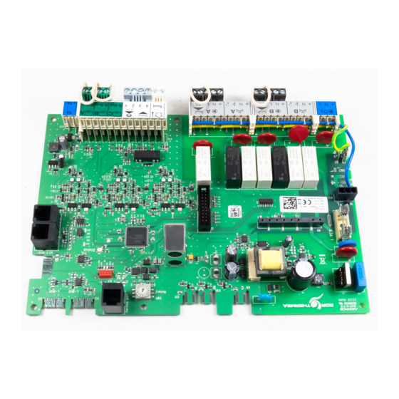
    Name Software­ Software­ version version SCB-10 01.03 1.03 Erweiterungsleiterplatte Die SCB-10 stellt die Funktionalität für einen TWW- SCB-10 und drei Heizkreise sowie einen 0-10 V-Anschluss für eine PWM-Systempumpe und einen potentialfreien Kontakt zur Statusbenachrichtigung bereit. 7747028 - v.01 - 25112019...
  • Seite 197: Anschlussmöglichkeiten Für Die Erweiterungsleiterplatte - Scb-10

    2 Produktbeschreibung Anschlussmöglichkeiten für die Erweiterungsleiterplatte - SCB-10 Es können verschiedene Heizkreise an die SCB-10 Leiterplatte angeschlossen werden. Regelung von zwei an Steckverbinder X15 angeschlossenen (Mischer)kreisen Regelung eines dritten (Mischer-)kreises über eine Erweiterungsleiterplatte (=Zubehör) an Steckverbinder X8 angeschlossen Regelung eines Trinkwasserkreises (TWW) Kaskadenanordnung (Fühler zu Fühlersystem 1 oder 2 hinzufügen)
  • Seite 198: Identifikationsnummer

    Drehknopf für Es gibt einen Drehknopf auf der Regelungsleiterplatte der folgenden Identifikationsnummer Produkte: SCB-10 Mit dem Drehknopf kann eine Identifikationsnummer für die Regelungsleiterplatte ausgewählt werden. Wenn mehrere Regelungsleiterplatten mit Drehknopf verwendet werden, kann jede Regelungsleiterplatte mit Drehknopf eine eindeutige Identifikationsnummer aufweisen.
  • Seite 199: Vor Der Installation

    10 = TWW Schichten 11 = Interner TWWSpeicher (1) Die Zahl entspricht der Nummer des Kreises, die mit der Drehscheibe an der SCB-10 eingestellt werden kann. (2) Mit Option AD249. (3) Die letzte Zahl des Parameters bezieht sich auf die Zone. Mithilfe des Codes kann die Parametereinstellung in den Anschlussbeispielen identifiziert werden.
  • Seite 200: Einstellung Der 0-10 Volt Eingangsfunktion Der Scb-10

    11 = Interner TWWSpeicher Einstellung zur Steuerung der Trinkwarmwasserwasserbereitung für Heizkessel mit integ­ riertem Speicher. Einstellung der 0-10 Volt Eingangsfunktion der SCB-10 Zur Regelung des 0-10 Volteingangs der SCB-10-Leiterplatte stehen drei verschiedene Möglichkeiten zur Auswahl: Deaktivieren der Eingangsfunktion. Der Eingang ist temperaturabhängig.
  • Seite 201: Analoge Leistungsorientierte Regelung

    3 Vor der Installation 3.2.2 Analoge leistungsorientierte Regelung Das 0 bis 10-V-Signal regelt die Leistung des Heizkessels. Der Regler moduliert auf Grundlage der Heizleistung. Die Minimalleistung hängt mit der Modulationstiefe des Heizkessels zusammen. Die Leistung variiert zwischen dem Minimal- und Maximalwert auf Grundlage des vom Regler festgelegten Wertes.
  • Seite 202: Anwendungsbeispiel

    3 Vor der Installation Abb.74 Parallele Kaskadenregelung 1 Alle Kessel in der Kaskade werden eingeschaltet, wenn die Systemtemperatur 3 °C unter dem Sollwert liegt. 2 Der erste Kessel schaltet ab, wenn die Systemtemperatur 3 °C über dem Sollwert liegt. 3 Nach 4 Minuten schaltet der zweite Kessel ab, wenn ΔT< 6K und wenn die Systemtemperatur immer noch mehr als 3 °C über dem Sollwert liegt.
  • Seite 203 3 Vor der Installation Symbol Erklärungen Hydraulische Weiche Durchlauferhitzer Primärer Heizkreisanschluss Sonnenkollektor Trinkwasserspeicher Fremdstromanode Elektrisches Heizelement Dusche Heizkreis Fußbodenheizung Verteiler Fußbodenheizung Warmluftheizung Schwimmbad (1) Im Trinkwasserspeicher eingebaut. 7747028 - v.01 - 25112019...
  • Seite 204: Anschlussbeispiel 1

    S out RU.C RU.B RU.A S.SYST.1 S.SYST.2 S.DHW S.DEP.C S.DEP.B S.DEP.A +TA- AD-4100046-01 A Heizkessel C Warmwasserkreis-DHW (1 Fühler ) B Ungemischter Kreis - CircA Wichtig: Alle Werkseinstellungen der SCB-10 sind für diesen Anschluss passend. 7747028 - v.01 - 25112019...
  • Seite 205: Anschlussbeispiel 2

    0-10V S out RU.C RU.B RU.A S.SYST.1 S.SYST.2 S.DHW S.DEP.C S.DEP.B S.DEP.A +TA- AD-4100047-01 A Heizkessel C Mischerkreis - CircB B Ungemischter Kreis - CircA Wichtig: Alle Werkseinstellungen der SCB-10 sind für diesen Anschluss passend. 7747028 - v.01 - 25112019...
  • Seite 206: Anschlussbeispiel 3

    S out RU.C RU.B RU.A S.SYST.1 S.SYST.2 S.DHW S.DEP.C S.DEP.B S.DEP.A +TA- AD-4100048-01 A Heizkessel C WW-Kreis - DHWA (1 Fühler) B Mischerkreis - CircB1 Wichtig: Alle Werkseinstellungen der SCB-10 sind für diesen Anschluss passend. 7747028 - v.01 - 25112019...
  • Seite 207: Anschlussbeispiel 4

    3 Vor der Installation 3.4.5 Anschlussbeispiel 4 Abb.78 1 Heizkessel + 1 ungemischter Kreis + 1 Mischerkreis + Warmwasserkreis (WW) AD-4100037-01 L-BUS CB-01 SCB-10 S-BUS Pump 0-10 On/off Tout 0-10V S out RU.C RU.B RU.A S.SYST.1 S.SYST.2 S.DHW S.DEP.C S.DEP.B S.DEP.A...
  • Seite 208 3 Vor der Installation Tab.116 Ein > > Installationseinstellungen > SCB-10 > DHWA > Parameter, Zähler, Signale > Parameter Code Anzeigetext Beschreibung Bereich Einstellung CP022 HK/Verbrauch., Fkt. Funktion des Heizkreises oder 0 = Aus Verbrauchers 1 = Direkt 2 = Mischerheizkreis...
  • Seite 209: Anschlussbeispiel 5

    B Pufferspeicher E Mischerkreis - CircC C Mischerkreis - CircA F WW-Kreis - DHWA (1 Fühler) Tab.118 Ein > > Installationseinstellungen > SCB-10 > Puffer mit 2 Fühler > Parameter, Zähler, Signale > Parameter Code Anzeigetext Beschreibung Bereich Einstellung BP001...
  • Seite 210 3 Vor der Installation Tab.119 Ein > > Installationseinstellungen > SCB-10 > CIRCA> Parameter, Zähler, Signale > Parameter Code Anzeigetext Beschreibung Bereich Einstellung CP000 BereichTVorlSollwMax Maximaler Sollwertbereich für die 7 °C - 100 °C Vorlauftemperatur CP010 HK,TVorlauf Soll Fester Vorlaufsollwert für den Heizkreis 7 °C - 100 °C...
  • Seite 211: Anschlussbeispiel 6

    3 Vor der Installation 3.4.7 Anschlussbeispiel 6 Abb.80 1 Heizkessel + 1 Mischerkreis + 1 ungemischte Kreis + Schwimmbadkreis + Warmwasserkreis (WW) AD-4100039-01 L-BUS CB-01 SCB-10 S-BUS Pump 0-10 On/off Tout 0-10V S out RU.C RU.B RU.A S.SYST.1 S.SYST.2 S.DHW S.DEP.C S.DEP.B...
  • Seite 212 8 = Zeitprogramm 9 = Prozesswärme 10 = TWW Schichten 11 = Interner TWWSpeicher 31 = EXT TWW-FWS Tab.121 Ein > > Installationseinstellungen > SCB-10 > CIRCC > Parameter, Zähler, Signale > Parameter Code Anzeigetext Beschreibung Bereich Einstellung CP023 HK/Verbrauch., Fkt.
  • Seite 213 3 Vor der Installation Tab.123 Ein > > Installationseinstellungen > SCB-10 > AUX > Parameter, Zähler, Signale > Parameter Code Anzeigetext Beschreibung Bereich Einstellung CP024 HK/Verbrauch., Fkt. Funktion des Heizkreises oder 0 = Aus Verbrauchers 1 = Direkt 2 = Mischerheizkreis...
  • Seite 214: Anschlussbeispiel 10

    3 Vor der Installation 3.4.8 Anschlussbeispiel 10 Abb.81 1 Heizkessel (A) + hydraulische Weiche + 2 Mischgruppen (B, C) + Heizkesselgruppe (D) AD-4100040-01 L-BUS CB-01 SCB-10 S-BUS Pump 0-10 On/off Tout 0-10V S out RU.C RU.B RU.A S.SYST.1 S.SYST.2 S.DHW S.DEP.C S.DEP.B...
  • Seite 215 6 TWW-Speicher 7 TWW elektrisch 8 Zeitprogramm 9 Prozesswärme 10 TWW Schichten 11 Interner TWWSpeicher 31 EXT TWW-FWS Tab.125 > Installationseinstellungen > SCB-10 > DHWA > Parameter, Zähler, Signale > Parameter Code Anzeigetext Beschreibung Bereich Einstellung CP022 HK/Verbrauch., Fkt. Funktion des Heizkreises oder...
  • Seite 216: Anschlussbeispiel 11

    E Mischerkreis - CircC (Fußbodenheizung) B Hydraulische Weiche F WW-Kreis - DHWA (Stufen-Warmwasserbereiter - 2 C Mischerkreis - CircA Fühler) D Mischerkreis - CircB Tab.127 Ein > > Installationseinstellungen >SCB-10 > CIRCA> Parameter, Zähler, Signale > Parameter Code Anzeigetext Beschreibung Bereich Einstellung CP000 BereichTVorlSollwMax Maximaler Sollwertbereich für die...
  • Seite 217 11 Interner TWWSpeicher 31 EXT TWW-FWS CP230 HK, Steigung Heizk Steigung der Heizkennlinie des 0 - 4 Heizkreises Tab.128 Ein > > Installationseinstellungen > SCB-10 > DHWA > Parameter, Zähler, Signale > Parameter Codierungs­ Anzeigetext Beschreibung Bereich Einstellung einheit CP022 HK/Verbrauch., Fkt.
  • Seite 218 3 Vor der Installation Tab.131 Ein > > Installationseinstellungen > SCB-10 > Anal. Eingang > Parameter, Zähler, Signale > Erweiterte Parameter Code Anzeigetext Beschreibung Bereich Einstellung EP036 Auswahl Fühlertyp Auswahl des Fühlertyps 0 = deaktiviert 1 = TWW-Speicher 2 = WW-Speicher oben 3 = Pufferspeicherfühler...
  • Seite 219: Anschlussbeispiel 12

    3 Vor der Installation 3.4.10 Anschlussbeispiel 12 Abb.83 1 Heizkessel + hydraulische Weiche + 1 ungemischter Kreis + 1 Mischerkreis + Warmwasserkreis (WW) AD-4100042-01 L-BUS CB-01 SCB-10 S-BUS Pump 0-10 On/off Tout 0-10V S out RU.C RU.B RU.A S.SYST.1 S.SYST.2 S.DHW...
  • Seite 220 Akt. Master Funkt. Aktiviere Master Funktionalität für dieses 0 = Nein Gerät auf dem S-Bus für 1 = Ja Systemkontrolle Tab.135 Installationseinstellungen > SCB-10 > Anal. Eingang > Parameter, Zähler, Signale > Erweiterte Parameter Code Anzeigetext Beschreibung Bereich Einstellung EP036 Auswahl Fühlertyp...
  • Seite 221: Anschlussbeispiel 14

    AD-4100055-01 A Heizkessel (Master) A-B S-BUS-Kabel (wird mit 2 Widerständen geliefert: B Heizkessel (Slave) einem am Steckverbinder X5 auf der SCB-10 C Hydraulische Weiche Leiterplatte und einem am Steckverbinder X10 an D Mischerkreis - CircC der CB-01 Leiterplatte von Heizkessel B) E WW-Kreis - DHWA (Stufen-Warmwasserbereiter - 2 Fühler)
  • Seite 222 Akt. Master Funkt. Aktiviere Master Funktionalität für dieses 0 = Nein Gerät auf dem S-Bus für 1 = Ja Systemkontrolle Tab.139 Installationseinstellungen > SCB-10 > Anal. Eingang > Parameter, Zähler, Signale > Erweiterte Parameter Code Anzeigetext Beschreibung Bereich Einstellung EP036 Auswahl Fühlertyp...
  • Seite 223: Anschlussbeispiel 16

    Fühler) C Hydraulische Weiche A-B S-BUS-Kabel (wird mit 2 Widerständen geliefert: D Mischerkreis - CircA einem am Steckverbinder X5 auf der SCB-10 E Mischerkreis - CircB Leiterplatte und einem am Steckverbinder X10 an F Mischerkreis - CircC der CB-01 Leiterplatte von Heizkessel B)
  • Seite 224 11 = Interner TWWSpeicher 31 = EXT TWW-FWS CP230 HK, Steigung Heizk Steigung der Heizkennlinie des 0 – 4 Heizkreises Tab.141 Installationseinstellungen > SCB-10 > DHWA > Parameter, Zähler, Signale > Parameter Code Anzeigetext Beschreibung Bereich Einstellung CP022 HK/Verbrauch., Fkt.
  • Seite 225 Akt. Master Funkt. Aktiviere Master Funktionalität für dieses 0 = Nein Gerät auf dem S-Bus für 1 = Ja Systemkontrolle Tab.144 Installationseinstellungen > SCB-10 > Anal. Eingang > Parameter, Zähler, Signale > Erweiterte Parameter Code Anzeigetext Beschreibung Bereich Einstellung EP036 Auswahl Fühlertyp...
  • Seite 226: Installation

    4 Installation Installation Elektrische Anschlüsse 4.1.1 Anschluss einer Trinkwasserpumpe Anschluss einer Trinkwasserpumpe. Die maximale Leistungsaufnahme beträgt 300 VA. Abb.86 Trinkwasserpumpenanschluss Die Pumpe wie folgt anschließen: Schutzleiter N Nullleiter L Phase AD-4000123-01 4.1.2 Anschluss eines Mischventils Anschließen eines Mischventils (230 VAC) pro Kreis (Gruppe). Abb.87 Mischventil-Stecker Das Mischventil wie folgt anschließen:...
  • Seite 227: Anschluss Von Raumgeräten Pro Kreis

    Anschluss von Raumgeräten pro Kreis Abb.91 R-Bus-Anschlüsse Der SCB-10 ist mit drei R-Bus Steckverbindern ausgestattet. Sie können zum Anschluss von Raumgeräten pro Kreis verwendet werden. Die R-bus Steckverbinder sind mit den anderen kreisspezifischen Steckverbindern an der SCB-10 verbunden. Der R-Bus Steckverbinder unterstützt folgende R-Bus R-Bus R-Bus Raumgerätetypen:...
  • Seite 228 4 Installation Abb.95 Anodenanschluss Die Anode wie folgt anschließen: + Anschluss an den Warmwasserspeicher - Anschluss an die Anode + TA - Vorsicht! Wenn der Trinkwarmwasserspeicher über keine TAS-Anode verfügt, die Simulationsanode (= Zubehör) anschließen AD-4000005-02 7747028 - v.01 - 25112019...
  • Seite 229: Einstellungen

    Menüpfad Benutzer > Untermenü Basis-Fachmann > Installationseinstellungen > SCB-10 > Untermenü > Parameter, Zähler, Signale > Parameter (1) Siehe die Spalte "Untermenü" in der nachfolgenden Tabelle zur korrekten Navigation. Die Parameter sind nach Funktionalitäten unter­ teilt. (2) Siehe die Spalte "Untermenü" in der nachfolgenden Tabelle zur korrekten Navigation. Die Parameter sind nach Funktionalitäten unter­...
  • Seite 230 5 Einstellungen Code Anzeigetext Beschreibung Bereich Untermenü Untermenü Stan­ dard­ einstel­ lung AP081 Kurzer Name Kurzer Name des Gerätes/ System Gerät Anlage Functionalit AP089 Name FHW Name des Fachhandwerkers notw. Busmaster AP090 Telefonnr. FHW Telefonnummer des notw. Fachhandwerkers Busmaster CP010 HK,TVorlauf Fester Vorlaufsollwert für den 7 °C - 100 °C...
  • Seite 231 5 Einstellungen Code Anzeigetext Beschreibung Bereich Untermenü Untermenü Stan­ dard­ einstel­ lung CP152 HKUmgKühlen Temperatursollwert für das 20 °C - 30 °C DHW 1 CP153 1Sollw Kühlen des Heizkreisraums CP154 CP155 CP156 CP157 CP158 HKUmgKühlen Temperatursollwert für das 20 °C - 30 °C CIRCC 1 CP159 1Sollw...
  • Seite 232 Menüpfad Heizungsfachmann > Untermenü Heizungsfachmann > Installationseinstellungen > SCB-10 > Untermenü > Parameter, Zähler, Signale > Parameter (1) Siehe die Spalte "Untermenü" in der nachfolgenden Tabelle zur korrekten Navigation. Die Parameter sind nach Funktionalitäten unter­ teilt. (2) Siehe die Spalte "Untermenü" in der nachfolgenden Tabelle zur korrekten Navigation. Die Parameter sind nach Funktionalitäten unter­...
  • Seite 233 5 Einstellungen Code Anzeigetext Beschreibung Bereich Untermenü Untermenü Stan­ dard­ einstel­ lung AP091 Verbind. Art der für den Außenfühler zu 0 = Automatisch Außentemp Außenfühler verwendenden Verbindung 1 = Verkabelter Sensor .fühler 2 = Funksensor 3 = Internet gemessen 4 = Keine BP001 Pufferspeichert Pufferspeichertyp...
  • Seite 234 5 Einstellungen Code Anzeigetext Beschreibung Bereich Untermenü Untermenü Stan­ dard­ einstel­ lung CP020 HK/Verbrauch., Funktion des Heizkreises oder 0 = Aus CIRCA 1 CP021 Fkt. Verbrauchers 1 = Direkt CIRCB 1 CP022 2 = Mischerheizkreis DHW 1 CP023 3 = Schwimmbad CIRCC 1 CP024 4 = Hochtemperatur...
  • Seite 235 5 Einstellungen Code Anzeigetext Beschreibung Bereich Untermenü Untermenü Stan­ dard­ einstel­ lung CP240 HK, Einfluss Einfluss des Raumfühlers auf den 0 - 10 CIRCA 1 CP241 Heizkreis CIRCB 1 CP242 DHW 1 CP243 CIRCC 1 CP244 AUX 1 CP270 Mischsollwert Vorlauftemperatur 11 °C - 23 °C CIRCA 1 CP271...
  • Seite 236 5 Einstellungen Code Anzeigetext Beschreibung Bereich Untermenü Untermenü Stan­ dard­ einstel­ lung CP460 TWWPriorität Wahl der TWW-Priorität 0 = Absolut CIRCA 1 CP461 1 = Gleitend CIRCB 1 CP462 2 = Keine DHW 1 CP463 CIRCC 1 CP464 AUX 1 CP470 HK, Estrich, Einstellung des...
  • Seite 237 5 Einstellungen Code Anzeigetext Beschreibung Bereich Untermenü Untermenü Stan­ dard­ einstel­ lung CP650 Nachtsollw.Kühl Umgebungssollwert in der Nacht 20 °C - 30 °C CIRCA 1 CP651 für das Kühlen je Heizkreis CIRCB 1 CP652 DHW 1 CP653 CIRCC 1 CP654 AUX 1 CP690 Invert.
  • Seite 238 5 Einstellungen Code Anzeigetext Beschreibung Bereich Untermenü Untermenü Stan­ dard­ einstel­ lung EP018 Funkt. Stat. Funktion Statusrelais 0 = Keine Akt.Stat.Ge Relais 1 = Alarm rät 2 = Alarm invertiert 3 = Brenner An 4 = Brenner Aus 5 = Reserviert 6 = Reserviert Wartungsanforderung 8 = Heizbetrieb...
  • Seite 239 Erweiterte Fachhand­ > Untermenü > ADV werkerebene Erweiterte Fachhand­ > Installationseinstellungen > SCB-10 > Untermenü > Parameter, Zähler, Signale > Erweiterte werkerebene Parameter (1) Siehe die Spalte "Untermenü" in der nachfolgenden Tabelle zur korrekten Navigation. Die Parameter sind nach Funktionalitäten unter­...
  • Seite 240 5 Einstellungen Code Anzeigetext Beschreibung Bereich Untermenü Untermenü Stan­ dard­ einstel­ lung CP680 Bus-Kanal RG Auswahl des Bus-Kanals des 0 - 255 CIRCA 1 CP681 zu HK Raumgeräts für den Heizkreis CIRCB 1 CP682 DHW 1 CP683 CIRCC 1 CP684 AUX 1 CP730 Auswahl der...
  • Seite 241: Auslesen Der Betriebsdaten

    Ebene Menüpfad Benutzer > SCB-10 Basis-Fachmann > Installationseinstellungen > SCB-10 > Untermenü > Parameter, Zähler, Signale > Zähler (1) Siehe die Spalte "Untermenü" in der nachfolgenden Tabelle zur korrekten Navigation. Die Zähler sind in spezifischen Funktionen unter­ teilt. Tab.152 Zähler auf Benutzer- / Basis-Fachmann-Ebene...
  • Seite 242 5 Einstellungen Code Anzeigetext Beschreibung Bereich Unterme­ nü CC002 Betriebsstd. Pumpe Die Betriebsstunden der Pumpe 0 - 4294967294 Paramet erPHKdir Zone Mischven Schwim mbad Hochtem pzone Gebläsek onvektzo Trinkwas Speicher Heizstab Prozess wärme TWW- Sch.Sp. Gewerbl. TWW- CC003 Betriebsstd. Pumpe Die Betriebsstunden der Pumpe 0 - 4294967294 Paramet...
  • Seite 243 5 Einstellungen Code Anzeigetext Beschreibung Bereich Unterme­ nü CC004 Betriebsstd. Pumpe Die Betriebsstunden der Pumpe 0 - 4294967294 Paramet erPHKdir Zone Mischven Schwim mbad Hochtem pzone Gebläsek onvektzo Trinkwas Speicher Heizstab Prozess wärme TWW- Sch.Sp. Gewerbl. TWW- CC005 Betriebsstd. Pumpe Die Betriebsstunden der Pumpe 0 - 4294967294 Paramet...
  • Seite 244 5 Einstellungen Code Anzeigetext Beschreibung Bereich Unterme­ nü CC010 Pumpenstarts HK Die Anzahl der Pumpenstarts 0 - 4294967294 Paramet erPHKdir Zone Mischven Schwim mbad Hochtem pzone Gebläsek onvektzo Trinkwas Speicher Heizstab Prozess wärme TWW- Sch.Sp. Gewerbl. TWW- CC011 Pumpenstarts HK Die Anzahl der Pumpenstarts 0 - 4294967294 Paramet...
  • Seite 245 5 Einstellungen Code Anzeigetext Beschreibung Bereich Unterme­ nü CC012 Pumpenstarts HK Die Anzahl der Pumpenstarts 0 - 4294967294 Paramet erPHKdir Zone Mischven Schwim mbad Hochtem pzone Gebläsek onvektzo Trinkwas Speicher Heizstab Prozess wärme TWW- Sch.Sp. Gewerbl. TWW- 7747028 - v.01 - 25112019...
  • Seite 246 5 Einstellungen Code Anzeigetext Beschreibung Bereich Unterme­ nü CC013 Pumpenstarts HK Die Anzahl der Pumpenstarts 0 - 4294967294 Paramet erPHKdir Zone Mischven Schwim mbad Hochtem pzone Gebläsek onvektzo Trinkwas Speicher Heizstab Prozess wärme TWW- Sch.Sp. Gewerbl. TWW- CC014 Pumpenstarts HK Die Anzahl der Pumpenstarts 0 - 4294967294 Paramet...
  • Seite 247: Signale Erweiterungsleiterplatte Scb-10

    Ebene Menüpfad Benutzer > SCB-10 Basis-Fachmann > Installationseinstellungen > SCB-10 > Untermenü > Parameter, Zähler, Signale > Signale (1) Siehe die Spalte "Untermenü" in der nachfolgenden Tabelle zur korrekten Navigation. Die Meldungen sind in spezifischen Funktionen unterteilt. Tab.154 Signale auf Benutzer- / Basis-Fachmann-Ebene...
  • Seite 248 5 Einstellungen Code Anzeigetext Beschreibung Bereich Unterme­ nü CM032 HKTRaum Raumtemperatur des Heizkreises 0 °C - 50 °C Paramet erPHKdir Zone Mischven Hochtem pzone Gebläsek onvektzo CM033 HKTRaum Raumtemperatur des Heizkreises 0 °C - 50 °C Paramet erPHKdir Zone Mischven Hochtem pzone Gebläsek...
  • Seite 249 5 Einstellungen Code Anzeigetext Beschreibung Bereich Unterme­ nü CM041 HK TVorlauf Vorlauftemperatur des Heizkreises -10 °C - 140 °C Zone Mischven Schwim mbad Trinkwas Speicher Heizstab Prozess wärme TWW- Sch.Sp. Gewerbl. TWW- CM042 HK TVorlauf Vorlauftemperatur des Heizkreises -10 °C - 140 °C Zone Mischven Schwim...
  • Seite 250 5 Einstellungen Code Anzeigetext Beschreibung Bereich Unterme­ nü CM044 HK TVorlauf Vorlauftemperatur des Heizkreises -10 °C - 140 °C Zone Mischven Schwim mbad Trinkwas Speicher Heizstab Prozess wärme TWW- Sch.Sp. Gewerbl. TWW- CM060 Pumpendrehzahl Pumpendrehzahl des Heizkreises 0 % - 100 % Paramet erPHKdir Zone...
  • Seite 251 5 Einstellungen Code Anzeigetext Beschreibung Bereich Unterme­ nü CM061 Pumpendrehzahl Pumpendrehzahl des Heizkreises 0 % - 100 % Paramet erPHKdir Zone Mischven Schwim mbad Hochtem pzone Gebläsek onvektzo Trinkwas Speicher Heizstab Prozess wärme TWW- Sch.Sp. Gewerbl. TWW- CM062 Pumpendrehzahl Pumpendrehzahl des Heizkreises 0 % - 100 % Paramet erPHKdir...
  • Seite 252 5 Einstellungen Code Anzeigetext Beschreibung Bereich Unterme­ nü CM063 Pumpendrehzahl Pumpendrehzahl des Heizkreises 0 % - 100 % Paramet erPHKdir Zone Mischven Schwim mbad Hochtem pzone Gebläsek onvektzo Trinkwas Speicher Heizstab Prozess wärme TWW- Sch.Sp. Gewerbl. TWW- CM064 Pumpendrehzahl Pumpendrehzahl des Heizkreises 0 % - 100 % Paramet erPHKdir...
  • Seite 253 5 Einstellungen Code Anzeigetext Beschreibung Bereich Unterme­ nü CM070 Temperatursollw. Temperatursollwert des Heizkreises 0 °C - 150 °C Paramet erPHKdir Zone Mischven Schwim mbad Hochtem pzone Gebläsek onvektzo Trinkwas Speicher Heizstab Prozess wärme TWW- Sch.Sp. Gewerbl. TWW- CM071 Temperatursollw. Temperatursollwert des Heizkreises 0 °C - 150 °C Paramet erPHKdir...
  • Seite 254 5 Einstellungen Code Anzeigetext Beschreibung Bereich Unterme­ nü CM072 Temperatursollw. Temperatursollwert des Heizkreises 0 °C - 150 °C Paramet erPHKdir Zone Mischven Schwim mbad Hochtem pzone Gebläsek onvektzo Trinkwas Speicher Heizstab Prozess wärme TWW- Sch.Sp. Gewerbl. TWW- CM073 Temperatursollw. Temperatursollwert des Heizkreises 0 °C - 150 °C Paramet erPHKdir...
  • Seite 255 5 Einstellungen Code Anzeigetext Beschreibung Bereich Unterme­ nü CM074 Temperatursollw. Temperatursollwert des Heizkreises 0 °C - 150 °C Paramet erPHKdir Zone Mischven Schwim mbad Hochtem pzone Gebläsek onvektzo Trinkwas Speicher Heizstab Prozess wärme TWW- Sch.Sp. Gewerbl. TWW- CM120 Betriebsart HK Aktuelle Betriebsart des Heizkreises 0 = Zeitprogramm Paramet...
  • Seite 256 5 Einstellungen Code Anzeigetext Beschreibung Bereich Unterme­ nü CM121 Betriebsart HK Aktuelle Betriebsart des Heizkreises 0 = Zeitprogramm Paramet 1 = Manuell erPHKdir 2 = Frostschutz 3 = Temporär Zone Mischven Schwim mbad Hochtem pzone Gebläsek onvektzo Trinkwas Speicher Heizstab TWW- Sch.Sp.
  • Seite 257 5 Einstellungen Code Anzeigetext Beschreibung Bereich Unterme­ nü CM123 Betriebsart HK Aktuelle Betriebsart des Heizkreises 0 = Zeitprogramm Paramet 1 = Manuell erPHKdir 2 = Frostschutz 3 = Temporär Zone Mischven Schwim mbad Hochtem pzone Gebläsek onvektzo Trinkwas Speicher Heizstab TWW- Sch.Sp.
  • Seite 258 5 Einstellungen Code Anzeigetext Beschreibung Bereich Unterme­ nü CM130 Akt. Funkt. HK Aktuelle Einstellung des Heizkreises 0 = Frostschutz Paramet 1 = Reduziert erPHKdir 2 = Komfort 3 = Anti-Legionellen Zone Mischven Schwim mbad Hochtem pzone Gebläsek onvektzo Trinkwas Speicher Heizstab Heizkreis Zeitpr.
  • Seite 259 5 Einstellungen Code Anzeigetext Beschreibung Bereich Unterme­ nü CM132 Akt. Funkt. HK Aktuelle Einstellung des Heizkreises 0 = Frostschutz Paramet 1 = Reduziert erPHKdir 2 = Komfort 3 = Anti-Legionellen Zone Mischven Schwim mbad Hochtem pzone Gebläsek onvektzo Trinkwas Speicher Heizstab Heizkreis Zeitpr.
  • Seite 260 5 Einstellungen Code Anzeigetext Beschreibung Bereich Unterme­ nü CM134 Akt. Funkt. HK Aktuelle Einstellung des Heizkreises 0 = Frostschutz Paramet 1 = Reduziert erPHKdir 2 = Komfort 3 = Anti-Legionellen Zone Mischven Schwim mbad Hochtem pzone Gebläsek onvektzo Trinkwas Speicher Heizstab Heizkreis Zeitpr.
  • Seite 261 5 Einstellungen Code Anzeigetext Beschreibung Bereich Unterme­ nü CM193 HK Sollwert TRaum Raumtemperatursollwert des Heizkreises 0 °C - 50 °C Paramet erPHKdir Zone Mischven Hochtem pzone Gebläsek onvektzo CM194 HK Sollwert TRaum Raumtemperatursollwert des Heizkreises 0 °C - 50 °C Paramet erPHKdir Zone...
  • Seite 262 5 Einstellungen Code Anzeigetext Beschreibung Bereich Unterme­ nü CM203 Akt. HeizBetrArt HK Heizkreis, aktuelle Heizbetriebsart 0 = Standby Paramet 1 = Heizen erPHKdir 2 = Kühlen Zone Mischven Schwim mbad Hochtem pzone Gebläsek onvektzo CM204 Akt. HeizBetrArt HK Heizkreis, aktuelle Heizbetriebsart 0 = Standby Paramet 1 = Heizen...
  • Seite 263 Ebene Menüpfad Heizungsfachmann > SCB-10 Heizungsfachmann > Installationseinstellungen > SCB-10 > Untermenü > Parameter, Zähler, Signale > Signale (1) Siehe die Spalte "Untermenü" in der nachfolgenden Tabelle zur korrekten Navigation. Die Meldungen sind in spezifischen Funktionen unterteilt. Tab.156 Signale auf Fachmannebene...
  • Seite 264 5 Einstellungen Code Anzeigetext Beschreibung Bereich Unterme­ nü BM002 Gem.PuSpTemp Gemessene Pufferspeichertemperatur -1 °C - 150 °C Passiver Puffer Sp Puffer mit 1 Fühler Puffer mit 2 Fühler BM020 Status Puffersp. Status Pufferspeicher 0 = Entkopplungstank Puffer 1 = Pufferspeicher mit 1 Fühler Puffer...
  • Seite 265 5 Einstellungen Code Anzeigetext Beschreibung Bereich Unterme­ nü CM163 HK Mod WA vorh. Eine modulierenden Wärmeanforderung 0 = Nein Paramet vorhanden 1 = Ja erPHKdir Zone Mischven Hochtem pzone Gebläsek onvektzo Heizstab TWW- Sch.Sp. CM164 HK Mod WA vorh. Eine modulierenden Wärmeanforderung 0 = Nein Paramet vorhanden...
  • Seite 266 Menüpfad Erweiterte Fach­ > SCB-10 mannebene Erweiterte Fach­ > Installationseinstellungen > SCB-10 > Untermenü > Parameter, Zähler, Signale > mannebene Erweiterte Signale (1) Siehe die Spalte "Untermenü" in der nachfolgenden Tabelle zur korrekten Navigation. Die Meldungen sind in spezifischen Funktionen unterteilt.
  • Seite 267 5 Einstellungen Tab.158 Signale auf erweiterter Fachmannebene Code Anzeigetext Beschreibung Bereich Unterme­ nü AP078 Außenfühler aktiv. Außentemperaturfühler für die Anwendung 0 = Nein Außente aktiviert 1 = Ja mp.fühler BM021 StatusPufferladepu Status Pufferladepumpe 0 = Aus Puffer 1 = Ein mit 1 Fühler Puffer...
  • Seite 268 5 Einstellungen Code Anzeigetext Beschreibung Bereich Unterme­ nü CM024 HKMVdÖffnen Mischventil-Öffnungszustand des 0 = Nein Zone Heizkreises 1 = Ja Mischven Schwim mbad Heizstab CM050 Pumpenbetrieb HK Pumpenstatus der Zone 0 = Nein Paramet 1 = Ja erPHKdir Zone Mischven Schwim mbad Hochtem...
  • Seite 269 5 Einstellungen Code Anzeigetext Beschreibung Bereich Unterme­ nü CM051 Pumpenbetrieb HK Pumpenstatus der Zone 0 = Nein Paramet 1 = Ja erPHKdir Zone Mischven Schwim mbad Hochtem pzone Gebläsek onvektzo Trinkwas Speicher Heizstab Heizkreis Zeitpr. Prozess wärme TWW- Sch.Sp. Gewerbl. TWW- CM052 Pumpenbetrieb HK...
  • Seite 270 5 Einstellungen Code Anzeigetext Beschreibung Bereich Unterme­ nü CM053 Pumpenbetrieb HK Pumpenstatus der Zone 0 = Nein Paramet 1 = Ja erPHKdir Zone Mischven Schwim mbad Hochtem pzone Gebläsek onvektzo Trinkwas Speicher Heizstab Heizkreis Zeitpr. Prozess wärme TWW- Sch.Sp. Gewerbl. TWW- CM054 Pumpenbetrieb HK...
  • Seite 271 5 Einstellungen Code Anzeigetext Beschreibung Bereich Unterme­ nü CM110 Raumtemperatursollwert, gesendet über 0 °C - 50 °C Paramet TRaumTempSollw. das Raumgerät des Heizkreises erPHKdir Zone Mischven Hochtem pzone Gebläsek onvektzo CM111 Raumtemperatursollwert, gesendet über 0 °C - 50 °C Paramet TRaumTempSollw.
  • Seite 272 5 Einstellungen Code Anzeigetext Beschreibung Bereich Unterme­ nü CM140 HK, OT vorhanden Vorhandensein von OpenTherm 0 = Nein Paramet 1 = Ja erPHKdir Zone Mischven Schwim mbad Hochtem pzone Gebläsek onvektzo Heizstab TWW- Sch.Sp. CM141 HK, OT vorhanden Vorhandensein von OpenTherm 0 = Nein Paramet 1 = Ja...
  • Seite 273 5 Einstellungen Code Anzeigetext Beschreibung Bereich Unterme­ nü CM143 HK, OT vorhanden Vorhandensein von OpenTherm 0 = Nein Paramet 1 = Ja erPHKdir Zone Mischven Schwim mbad Hochtem pzone Gebläsek onvektzo Heizstab TWW- Sch.Sp. CM144 HK, OT vorhanden Vorhandensein von OpenTherm 0 = Nein Paramet 1 = Ja...
  • Seite 274 5 Einstellungen Code Anzeigetext Beschreibung Bereich Unterme­ nü CM151 HK, WA Ein/Aus Vorhandensein Wärmeanforderung 0 = Nein Paramet Ein/Aus 1 = Ja erPHKdir Zone Mischven Schwim mbad Hochtem pzone Gebläsek onvektzo Heizstab TWW- Sch.Sp. CM152 HK, WA Ein/Aus Vorhandensein Wärmeanforderung 0 = Nein Paramet Ein/Aus...
  • Seite 275 5 Einstellungen Code Anzeigetext Beschreibung Bereich Unterme­ nü CM154 HK, WA Ein/Aus Vorhandensein Wärmeanforderung 0 = Nein Paramet Ein/Aus 1 = Ja erPHKdir Zone Mischven Schwim mbad Hochtem pzone Gebläsek onvektzo Heizstab TWW- Sch.Sp. CM180 HK Raumgerät vorh. Vorhandensein eines Raumgeräts 0 = Nein Paramet 1 = Ja...
  • Seite 276 5 Einstellungen Code Anzeigetext Beschreibung Bereich Unterme­ nü CM181 HK Raumgerät vorh. Vorhandensein eines Raumgeräts 0 = Nein Paramet 1 = Ja erPHKdir Zone Mischven Schwim mbad Hochtem pzone Gebläsek onvektzo Trinkwas Speicher Heizstab Prozess wärme TWW- Sch.Sp. Gewerbl. TWW- CM182 HK Raumgerät vorh.
  • Seite 277 5 Einstellungen Code Anzeigetext Beschreibung Bereich Unterme­ nü CM183 HK Raumgerät vorh. Vorhandensein eines Raumgeräts 0 = Nein Paramet 1 = Ja erPHKdir Zone Mischven Schwim mbad Hochtem pzone Gebläsek onvektzo Trinkwas Speicher Heizstab Prozess wärme TWW- Sch.Sp. Gewerbl. TWW- CM184 HK Raumgerät vorh.
  • Seite 278 5 Einstellungen Code Anzeigetext Beschreibung Bereich Unterme­ nü CM241 HK, Außt. Außentemperatur ist verbunden mit 0 = Nein Paramet verbunden Heizkreis 1 = Ja erPHKdir Zone Mischven Hochtem pzone Gebläsek onvektzo CM242 HK, Außt. Außentemperatur ist verbunden mit 0 = Nein Paramet verbunden Heizkreis...
  • Seite 279 5 Einstellungen Code Anzeigetext Beschreibung Bereich Unterme­ nü CM281 Raumsoll m. Interner Raumtemperatur-Sollwert 0 °C - 100 °C Paramet Einfluss berechnet durch die erPHKdir Raumtemperaturregelung des Heizkreises Zone Mischven Hochtem pzone Gebläsek onvektzo CM282 Raumsoll m. Interner Raumtemperatur-Sollwert 0 °C - 100 °C Paramet Einfluss berechnet durch die...
  • Seite 280: Scb-10 Status Und Substatus

    NM002 Akt. Zeit n. Stufe Aktuelle Zeit zum zuschalten der nächsten 0 Min - 60 Min Kaskade Stufe nreglung 5.3.3 SCB-10 Status und Substatus Tab.159 AM012 - Status Be­ Status Erklärungen reich Standby Das Gerät befindet sich im Standbybetrieb. Wärmeanforderung Eine Heizanforderung ist aktiv.
  • Seite 281 5 Einstellungen Be­ Status Erklärungen reich Warten auf Startbed. Das Gerät wartet, bis die Temperatur die Startbedin­ gungen erfüllt. Ext.Gasvent.schließ Ein externes Gasventil wird geöffnet, wenn diese Opti­ on an das Gerät angeschlossen ist. Zur Ansteuerung des Ventils muss eine zusätzliche externe Leiterplatte angeschlossen werden.
  • Seite 282 5 Einstellungen Be­ Status Erklärungen reich Initialisierung CSU Die CSU initialisiert. Init. Identifikat. Die Identifikatoren werden initialisiert. Init.Sperr-Parameter Die Sperrparameter werden initialisiert. Init. Sicherh.modul Die Sicherheitseinheit wird initialisiert. Init. Sperrung Die Blockierung wird initialisiert. Status unbekannt Der Subzustand ist nicht definiert. SuAuss.Rücks.Wart1h Die Sicherheitseinheit blockiert aufgrund zu vieler Rücksetzungen.
  • Seite 283: Fehlerbehebung

    6 Fehlerbehebung Fehlerbehebung Warnung - SCB-10 Tab.161 Warncodes Code Anzeigetext Beschreibung Abhilfe A00.32 TAußen Offen Außentemperaturfühler wurde entfernt oder Außentemperaturfühler offen: misst eine Temperatur unter dem zulässigen Schlechte Verbindung: Ver­ Bereich kabelung und Anschlüsse überprüfen. Falsch angebrachter Sen­ sor: Überprüfen, ob der Fühler korrekt montiert ist...
  • Seite 284 6 Fehlerbehebung Code Anzeigetext Beschreibung Abhilfe A10.33 Unt. Schw.fü. Zone D Unterbruch Schwimmbadtemperaturfühler Fühler für die Obergrenze der Zone D Trinkwarmwassertemperatur offen: Schlechte Verbindung: Ver­ kabelung und Anschlüsse überprüfen. Falsch angebrachter Sen­ sor: Überprüfen, ob der Fühler korrekt montiert ist Sensor ist nicht vorhanden.
  • Seite 285: Sperrung - Scb-10

    Den Fühler an­ schließen Der Trinkwarmwasser-Tem­ peraturfühler ist nicht richtig angeschlossen: Den Fühler richtig anschließen Fühler defekt: Fühler aus­ tauschen Sperrung - SCB-10 Tab.162 Sperrcodes Code Anzeigetext Beschreibung Abhilfe H00.69 Unterbr. Puffersp.Fü Unterbruch Pufferspeicherfühler Temperaurfühler Pufferspeicher offen: oder unterhalb des zulässigen...
  • Seite 286 6 Fehlerbehebung Code Anzeigetext Beschreibung Abhilfe H00.71 Unt. ob. Puffersp.Fü Unterbruch oberer Oberer Temperaurfühler Pufferspeicher offen: Pufferspeicherfühler oder unterhalb Schlechte Verbindung: Verkabelung und An­ des zulässigen Wertebereiches schlüsse überprüfen. Falsch angebrachter Sensor: Überprüfen, ob der Fühler korrekt montiert ist Sensor ist nicht vorhanden. Fühler defekt: Fühler austauschen H00.72 Kur.
  • Seite 287 6 Fehlerbehebung Code Anzeigetext Beschreibung Abhilfe H02.05 CSU Regel Mismatch CSU passt nicht zur Regelung Konfigurationsfehler: CN1 und CN2 zurücksetzen H02.16 Int. CSU Unterbr. Interne CSU Unterbrechung Konfigurationsfehler: CN1 und CN2 zurücksetzen PCB ersetzen H02.36 Funkt.Gerät getrennt Funktionelles Gerät wurde getrennt Fehler in der Datenübertragung mit der SCB-Lei­...
  • Seite 288 6 Fehlerbehebung Code Anzeigetext Beschreibung Abhilfe H02.67 Kurzsch. TAS Kurzschluss der aktiven Korrosionsschutzanode (TAS) fehlt oder ist kurz­ Fremdstromanode geschlossen: Schlechte Verbindung: Verkabelung und An­ schlüsse überprüfen. Falsch angebrachter Sensor: Überprüfen, ob der Fühler korrekt montiert ist Fühler defekt: Fühler austauschen H02.79 Anlag.verliert S-Bus Keine Anlage am Systembus...
  • Seite 289 6 Fehlerbehebung Code Anzeigetext Beschreibung Abhilfe H10.05 Ks. Schw.fü. Zone A Kurzschluss Schwimmbad-Temperaturfühler Zone A kurzge­ Schwimmbadtemperaturfühler Zone schlossen: Schlechte Verbindung: Verkabelung und An­ schlüsse überprüfen. Falsch angebrachter Sensor: Überprüfen, ob der Fühler korrekt montiert ist Fühler defekt: Fühler austauschen H10.09 Unt.
  • Seite 290 6 Fehlerbehebung Code Anzeigetext Beschreibung Abhilfe H10.18 Unt. Vorl.fü. Zone C Vorlauftemperaturfühler Zone C Vorlauftemperaturfühler Zone C offen: offen Schlechte Verbindung: Verkabelung und An­ schlüsse überprüfen. Falsch angebrachter Sensor: Überprüfen, ob der Fühler korrekt montiert ist Sensor ist nicht vorhanden. Fühler defekt: Fühler austauschen H10.19 Ks.
  • Seite 291 6 Fehlerbehebung Code Anzeigetext Beschreibung Abhilfe H10.28 Ks. Vorl.fü. Zone D Kurzschluss Vorlauftemp.fühler Vorlauftemperaturfühler Zone DHW kurzge­ Zone D schlossen: Schlechte Verbindung: Verkabelung und An­ schlüsse überprüfen. Falsch angebrachter Sensor: Überprüfen, ob der Fühler korrekt montiert ist Fühler defekt: Fühler austauschen H10.29 Unt.
  • Seite 292 Impostazione della funzione ingresso 0-10 volt dell'SCB-10 ........
  • Seite 293: Proposito Di Questo Manuale

    1 A proposito di questo manuale A proposito di questo manuale Simboli utilizzati nel manuale Questo manuale contiene istruzioni speciali, contrassegnate con simboli specifici. Si prega di prestare la massima attenzione a questi simboli. Attenzione Rischio di danni materiali. Importante Segnala un'informazione importante.
  • Seite 294: Descrizione Del Prodotto

    SCB-10 01.03 1.03 PCB di espansione La SCB-10 fornisce funzionalità per una zona ACS e SCB-10 tre zone di riscaldamento, un collegamento 0-10 V per una pompa dell'impianto PWM e un contatto pulito per le notifiche di stato. 7747028 - v.01 - 25112019...
  • Seite 295: Opzioni Di Collegamento Per La Pcb Di Espansione - Scb-10

    (aggiungere una sonda al sistema di sonde 1 o 2) Importante Nel caso in cui la PCB SCB-10 venga aggiunta in caldaia, questa viene automaticamente riconosciuta dal pannello di controllo automatico della caldaia stessa. Se questa scheda di controllo viene rimossa, sulla caldaia verrà...
  • Seite 296: Numero Di Identificazione

    Fig.102 Manopola per numero identificativo Sulla PCB dei seguenti prodotti è presente una manopola: SCB-10 La manopola può essere utilizzata per selezionare un numero identificativo per la PCB. Se sono in uso più PCB con una manopola, ogni PCB con una manopola può avere un numero unico per l'identificazione.
  • Seite 297: Prima Dell'installazione

    10 = Stratificazione ACS 11 = Accumulo ACS interno (1) Il numero fa riferimento al numero del circuito che può essere impostato ruotando la manopola sulla SCB-10. (2) Con opzione AD249. (3) L'ultimo numero del parametro si riferisce alla zona. È possibile utilizzare il codice per identificare le impostazioni del parametro negli esempi di collegamento.
  • Seite 298: Impostazione Della Funzione Ingresso 0-10 Volt Dell'scb-10

    Impostazione per la gestione dell'acqua calda sanitaria per le caldaie dotate di bollitore interno. Impostazione della funzione ingresso 0-10 volt dell'SCB-10 Vi sono tre opzioni per il comando dell'ingresso 0-10 volt dell'SCB-10: Disabilitare la funzione dell'ingresso. L'ingresso si basa su temperatura.
  • Seite 299: Regolazione Analogica In Potenza

    3 Prima dell'installazione 3.2.2 Regolazione analogica in potenza Il segnale 0 - 10 V regola la potenza della caldaia. Tale regolazione si modula sulla base della potenza termica. La potenza minima è collegata alla profondità di modulazione della caldaia. La potenza varia tra il valore di minima e di massima sulla base del valore stabilito dal regolatore.
  • Seite 300: Schemi Di Collegamento

    3 Prima dell'installazione Fig.107 Gestione del comando a cascata in 1 Tutte le caldaie nella cascata si avviano quando la temperatura parallelo dell'impianto risulta sotto il set point di 3°C. 2 La prima caldaia si arresta quando la temperatura dell'impianto risulta sopra il set point di 3°C.
  • Seite 301 3 Prima dell'installazione Simbolo Spiegazione Separatore idraulico Caldaia istantanea Collegamento al circuito di riscaldamento primario Collettore solare Bollitore sanitario Anodo di titanio Elemento riscaldante elettrico Doccia Zona di riscaldamento Riscaldamento a pavimento Collettore del riscaldamento a pavimento Riscaldatore ad aria calda Piscina (1) Montato all'interno del bollitore sanitario.
  • Seite 302: Esempio Di Collegamento 1

    RU.B RU.A S.SYST.1 S.SYST.2 S.DHW S.DEP.C S.DEP.B S.DEP.A +TA- AD-4100046-01 A Caldaia C Zona acqua calda sanitaria-ACS (1 sonda) B Zona diretta-CircA Importante Tutte le preimpostazioni per la SCB-10 risultano già accettabili per questo collegamento. 7747028 - v.01 - 25112019...
  • Seite 303: Esempio Di Collegamento 2

    RU.A S.SYST.1 S.SYST.2 S.DHW S.DEP.C S.DEP.B S.DEP.A +TA- AD-4100047-01 A Caldaia C Zona di miscelazione - CircB B Zona diretta - CircA Importante Tutte le preimpostazioni per la SCB-10 risultano già accettabili per questo collegamento. 7747028 - v.01 - 25112019...
  • Seite 304: Esempio Di Collegamento 3

    S.SYST.1 S.SYST.2 S.DHW S.DEP.C S.DEP.B S.DEP.A +TA- AD-4100048-01 A Caldaia C Zona ACS - DHWA (1 sonda) B Zona di miscelazione - CircB1 Importante Tutte le preimpostazioni per la SCB-10 risultano già accettabili per questo collegamento. 7747028 - v.01 - 25112019...
  • Seite 305: Esempio Di Collegamento 4

    3 Prima dell'installazione 3.4.5 Esempio di collegamento 4 Fig.111 1 caldaia + 1 zona diretta + 1 zona di miscelazione + zona acqua calda sanitaria (ACS) AD-4100037-01 L-BUS CB-01 SCB-10 S-BUS Pump 0-10 On/off Tout 0-10V S out RU.C RU.B RU.A...
  • Seite 306 3 Prima dell'installazione Tab.170 Acceso > > Processo di installazione > SCB-10 > DHWA > Parametri, contatori, segnali > Parametri Codice Testo visualizzato Descrizione Range Impostazio­ CP022 Funzionamento zona Funzionalità della zona 0 = Disabilitare 1 = Diretto 2 = Circuito miscelato...
  • Seite 307: Esempio Di Collegamento 5

    3 Prima dell'installazione 3.4.6 Esempio di collegamento 5 Fig.112 1 caldaia + serbatoio di accumulo + 3 zone di miscelazione + zona acqua calda sanitaria (ACS) AD-4100038-01 L-BUS CB-01 SCB-10 S-BUS Pump 0-10 On/off Tout 0-10V S out RU.C RU.B RU.A...
  • Seite 308 3 Prima dell'installazione Tab.172 Acceso > > Processo di installazione > SCB-10 > Serb acc pass 2 sens > Parametri, contatori, segnali > Parametri Codice Testo visualizzato Descrizione Range Impostazio­ BP001 Tipo serbatoio acc. Tipo di serbatoio di accumulo 0 = Disabilitato...
  • Seite 309: Esempio Di Collegamento 6

    3 Prima dell'installazione 3.4.7 Esempio di collegamento 6 Fig.113 1 caldaia + 1 zona di miscelazione + 1 zona diretta + zona piscina + zona acqua calda sanitaria (ACS) AD-4100039-01 L-BUS CB-01 SCB-10 S-BUS Pump 0-10 On/off Tout 0-10V S out RU.C...
  • Seite 310 9 = Riscaldam. processo 10 = Stratificazione ACS 11 = Accumulo ACS interno 31 = Staz.acq.frd.est.ACS Tab.175 Acceso > > Processo di installazione > SCB-10 > CIRCC > Parametri, contatori, segnali > Parametri Codice Testo visualizzato Descrizione Range Impostazio­ CP023 Funzionamento zona Funzionalità...
  • Seite 311 3 Prima dell'installazione Tab.177 Acceso > > Processo di installazione > SCB-10 > AUX > Parametri, contatori, segnali > Parametri Codice Testo visualizzato Descrizione Range Impostazio­ CP024 Funzionamento zona Funzionalità della zona 0 = Disabilitare 1 = Diretto 2 = Circuito miscelato...
  • Seite 312: Esempio Di Collegamento 10

    3 Prima dell'installazione 3.4.8 Esempio di collegamento 10 Fig.114 1 caldaia (A) + separatore idraulico + 2 gruppi di miscelazione (B, C) + gruppo caldaia (D) AD-4100040-01 L-BUS CB-01 SCB-10 S-BUS Pump 0-10 On/off Tout 0-10V S out RU.C RU.B RU.A...
  • Seite 313 7 ACS elettrica 8 Programmazione 9 Riscaldam. processo 10 Stratificazione ACS 11 Accumulo ACS interno 31 Staz.acq.frd.est.ACS Tab.179 > Processo di installazione > SCB-10 > DHWA > Parametri, contatori, segnali > Parametri Codice Testo visualizzato Descrizione Range Regolazione CP022 Funzionamento zona Funzionalità...
  • Seite 314: Esempio Di Collegamento 11

    C Zona di miscelazione - CircA F Zona ACS - ACSA (bollitore a stratificazione - 2 D Zona di miscelazione - CircB sonde) Tab.181 Acceso > > Processo di installazione >SCB-10 > CIRCA> Parametri, contatori, segnali > Parametri Codice Testo visualizzato Descrizione Range Impostazio­...
  • Seite 315 Pendenz Curv Ris zon Pendenza della curva di riscaldamento 0 - 4 della zona Tab.182 Acceso > > Processo di installazione > SCB-10 > DHWA > Parametri, contatori, segnali > Parametri Unità di co­ Testo visualizzato Descrizione Range Impostazio­ difica...
  • Seite 316 3 Prima dell'installazione Tab.184 Acceso > > Processo di installazione >SCB-10 > Gestione cascata B > Parametri, contatori, segnali > Parametri Codice Testo visualizzato Descrizione Range Impostazio­ AP083 Attiva funz. master Attiva la funzionalità master di questo 0 = No dispositivo su S-Bus per il controllo 1 = Sì...
  • Seite 317: Esempio Di Collegamento 12

    3 Prima dell'installazione 3.4.10 Esempio di collegamento 12 Fig.116 1 caldaia + separatore idraulico + 1 zona diretta + 1 zona di miscelazione + zona acqua calda sanitaria (ACS) AD-4100042-01 L-BUS CB-01 SCB-10 S-BUS Pump 0-10 On/off Tout 0-10V S out RU.C...
  • Seite 318 8 = Programmazione 9 = Riscaldam. processo 10 = Stratificazione ACS 11 = Accumulo ACS interno 31 = Staz.acq.frd.est.ACS Tab.188 Processo di installazione > SCB-10 > Gestione cascata B > Parametri, contatori, segnali > Parametri Codice Testo visualizzato Descrizione Range Impostazio­...
  • Seite 319: Esempio Di Collegamento 14

    A Caldaia (master) A-B Cavo S-BUS (fornito con 2 resistori; uno sul B Caldaia (slave) connettore X5 sulla PCB SCB-10 e uno sul C Separatore idraulico connettore X10 sulla PCB CB-01 della caldaia B) D Zona di miscelazione - CircC...
  • Seite 320 8 = Programmazione 9 = Riscaldam. processo 10 = Stratificazione ACS 11 = Accumulo ACS interno 31 = Staz.acq.frd.est.ACS Tab.192 Processo di installazione > SCB-10 > Gestione cascata B > Parametri, contatori, segnali > Parametri Codice Testo visualizzato Descrizione Range Impostazio­...
  • Seite 321: Esempio Di Collegamento 16

    C Separatore idraulico A-B Cavo S-BUS (fornito con 2 resistori; uno sul D Zona di miscelazione - CircA connettore X5 sulla PCB SCB-10 e uno sul E Zona di miscelazione - CircB connettore X10 sulla PCB CB-01 della caldaia B) F Zona di miscelazione - CircC 7747028 - v.01 - 25112019...
  • Seite 322 31 = Staz.acq.frd.est.ACS CP230 Pendenz Curv Ris zon Pendenza della curva di riscaldamento 0 – 4 della zona Tab.195 Processo di installazione > SCB-10 > DHWA > Parametri, contatori, segnali > Parametri Codice Testo visualizzato Descrizione Range Impostazio­ CP022 Funzionamento zona Funzionalità...
  • Seite 323 8 = Programmazione 9 = Riscaldam. processo 10 = Stratificazione ACS 11 = Accumulo ACS interno 31 = Staz.acq.frd.est.ACS Tab.197 Processo di installazione > SCB-10 > Gestione cascata B > Parametri, contatori, segnali > Parametri Codice Testo visualizzato Descrizione Range Impostazio­...
  • Seite 324: Installazione

    4 Installazione Installazione Collegamenti elettrici 4.1.1 Collegamento di una pompa per l'acqua calda sanitaria (ACS) Collegamento di una pompa per l'acqua calda sanitaria (ACS). La potenza massima assorbita è pari a 300 VA. Fig.119 Connettore pompa ACS Collegare la pompa come segue: Terra N Neutro L Fase...
  • Seite 325: Collegamento Dei Termostati Ambiente Per Zona

    Collegamento dei termostati ambiente per zona Fig.124 Connettori R-bus Il SCB-10 è montato con tre connettori R-Bus. Possono essere utilizzati per collegare i termostati ambiente per zona. I connettori R-bus sono collegati agli altri connettori specifici di zona su SCB-10.Il connettore R-...
  • Seite 326: Impostazioni

    Utente > Sottomenu Installatore di base > Processo di installazione > SCB-10 > Sottomenu > Parametri, contatori, segnali > Parametri (1) Vedere la colonna "Sottomenu" nella tabella seguente per la navigazione corretta. I parametri sono raggruppati in funzionalità specifi­ che.
  • Seite 327 5 Impostazioni Codice Testo visualiz­ Descrizione Range Sottomenu Sottomenu Impo­ zato stazio­ ne di fabbri­ AP081 Nome breve Nome breve del dispositivo Funzionalit disposit. à sistema AP089 Nome install. Nome dell'installatore Obbligo master bus AP090 Tel. installatore Numero di telefono Obbligo dell'installatore master bus...
  • Seite 328 5 Impostazioni Codice Testo visualiz­ Descrizione Range Sottomenu Sottomenu Impo­ zato stazio­ ne di fabbri­ CP152 ValImpAmbRaff Valore di impostazione 20 °C - 30 °C DHW 1 CP153 rArea1 temperatura ambiente di CP154 raffreddamento area CP155 CP156 CP157 CP158 ValImpAmbRaff Valore di impostazione 20 °C - 30 °C CIRCC 1...
  • Seite 329 Percorso del menu Installatore > Sottomenu Installatore > Processo di installazione > SCB-10 > Sottomenu > Parametri, contatori, segnali > Parametri (1) Vedere la colonna "Sottomenu" nella tabella seguente per la navigazione corretta. I parametri sono raggruppati in funzionalità specifi­ che.
  • Seite 330 5 Impostazioni Codice Testo visualiz­ Descrizione Range Sottomenu Sottomenu Impo­ zato stazio­ ne di fabbri­ AP083 Attiva funz. Attiva la funzionalità master di 0 = No Obbligo master questo dispositivo su S-Bus per il 1 = Sì master bus controllo dell'impianto Gestore prod.
  • Seite 331 5 Impostazioni Codice Testo visualiz­ Descrizione Range Sottomenu Sottomenu Impo­ zato stazio­ ne di fabbri­ BP015 Postfunz Durata minima del 0 Min - 20 Min Serb acc pompa serb. postfunzionamento della pompa pass 1 del serbatoio di accumulo sens Serb acc pass 2 sens BP019...
  • Seite 332 5 Impostazioni Codice Testo visualiz­ Descrizione Range Sottomenu Sottomenu Impo­ zato stazio­ ne di fabbri­ CP070 Tmax amb mod Limite max temp ambiente del 5 °C - 30 °C CIRCA 1 CP071 ridot circuito in mod. ridotta, che CIRCB 1 CP072 permette la commutazione a DHW 1...
  • Seite 333 5 Impostazioni Codice Testo visualiz­ Descrizione Range Sottomenu Sottomenu Impo­ zato stazio­ ne di fabbri­ CP400 Antileg. ACS Durata della funzione 10 Min - 600 Min CIRCA 1 CP401 area antilegionella CIRCB 1 CP402 DHW 1 CP403 CIRCC 1 CP404 AUX 1 CP420 Area,...
  • Seite 334 5 Impostazioni Codice Testo visualiz­ Descrizione Range Sottomenu Sottomenu Impo­ zato stazio­ ne di fabbri­ CP610 Ist PH on per Isteresi attivata per elaborazione 1 °C - 15 °C CIRCA 1 CP611 area calore per area CIRCB 1 CP612 DHW 1 CP613 CIRCC 1 CP614...
  • Seite 335 5 Impostazioni Codice Testo visualiz­ Descrizione Range Sottomenu Sottomenu Impo­ zato stazio­ ne di fabbri­ CP780 Strategia Selezione della strategia di 0 = Automatico CIRCA 1 CP781 controllo controllo della zona 1 = Temperatura CIRCB 1 CP782 ambiente DHW 1 CP783 2 = Temperatura esterna CIRCC 1...
  • Seite 336 > Sottomenu > ADV Installatore avanzato > Processo di installazione > SCB-10 > Sottomenu > Parametri, contatori, segnali > Parametri avanzati (1) Vedere la colonna "Sottomenu" nella tabella seguente per la navigazione corretta. I parametri sono raggruppati in funzionalità specifi­...
  • Seite 337 5 Impostazioni Tab.204 Impostazioni di fabbrica a livello installatore avanzato Codice Testo visualiz­ Descrizione Range Sottomenu Sottomenu Impo­ zato stazio­ ne di fabbri­ AP111 Lunghezza Lunghezza della linea Can 0 = < 3 m Obbligo AP112 linea Can 1 = < 80 m master bus 2 = <...
  • Seite 338: Lettura Dati Di Funzionamento

    Percorso del menu Utente > SCB-10 Installatore di base > Processo di installazione > SCB-10 > Sottomenu > Parametri, contatori, segnali > Contatori (1) Vedere la colonna "Sottomenu" nella tabella seguente per la navigazione corretta. I contatori sono raggruppati in funzionalità specifiche.
  • Seite 339 5 Impostazioni Tab.206 Contatori a livello utente / installatore di base Codice Testo visualizzato Descrizione Range Sottome­ AC001 Ore rete elettrica Numero di ore in cui l'apparecchio è stato 0 Orario - 4294967294 Orario Funziona collegato alla rete elettrica lità sistema CC001 Ore funz pompa...
  • Seite 340 5 Impostazioni Codice Testo visualizzato Descrizione Range Sottome­ CC003 Ore funz pompa Numero di ore di funzionamento pompa 0 - 4294967294 Circuito Zona nella zona diretto Zona mista Piscina Zona alta temp. Zona ventilcon vett. Serbatoi o ACS Boll. elettr. Elaborazi calore Serb.
  • Seite 341 5 Impostazioni Codice Testo visualizzato Descrizione Range Sottome­ CC005 Ore funz pompa Numero di ore di funzionamento pompa 0 - 4294967294 Circuito Zona nella zona diretto Zona mista Piscina Zona alta temp. Zona ventilcon vett. Serbatoi o ACS Boll. elettr. Elaborazi calore Serb.
  • Seite 342 5 Impostazioni Codice Testo visualizzato Descrizione Range Sottome­ CC011 Num avvii pompa Numero di volte che la pompa è stata 0 - 4294967294 Circuito Zona avviata nella zona diretto Zona mista Piscina Zona alta temp. Zona ventilcon vett. Serbatoi o ACS Boll.
  • Seite 343 5 Impostazioni Codice Testo visualizzato Descrizione Range Sottome­ CC013 Num avvii pompa Numero di volte che la pompa è stata 0 - 4294967294 Circuito Zona avviata nella zona diretto Zona mista Piscina Zona alta temp. Zona ventilcon vett. Serbatoi o ACS Boll.
  • Seite 344: Segnali Della Pcb Di Espansione Scb-10

    Percorso del menu Utente > SCB-10 Installatore di base > Processo di installazione > SCB-10 > Sottomenu > Parametri, contatori, segnali > Segnali (1) Vedere la colonna "Sottomenu" nella tabella seguente per la navigazione corretta. Le segnalazioni sono raggruppate in funzionalità spe­...
  • Seite 345 5 Impostazioni Codice Testo visualizzato Descrizione Range Sottome­ CM033 Tambiente Zona Temperatura ambiente nella zona 0 °C - 50 °C Circuito diretto Zona mista Zona alta temp. Zona ventilcon vett. CM034 Tambiente Zona Temperatura ambiente nella zona 0 °C - 50 °C Circuito diretto Zona...
  • Seite 346 5 Impostazioni Codice Testo visualizzato Descrizione Range Sottome­ CM042 TFlussoArea Temperatura di mandata della zona / -10 °C - 140 °C Zona temperatura ACS mista Piscina Serbatoi o ACS Boll. elettr. Elaborazi calore Serb. a stratif. Bollit.co mmer.AC CM043 TFlussoArea Temperatura di mandata della zona / -10 °C - 140 °C Zona...
  • Seite 347 5 Impostazioni Codice Testo visualizzato Descrizione Range Sottome­ CM060 Velocità Pompa Velocità attuale della pompa nella zona 0 % - 100 % Circuito Zona diretto Zona mista Piscina Zona alta temp. Zona ventilcon vett. Serbatoi o ACS Boll. elettr. Elaborazi calore Serb.
  • Seite 348 5 Impostazioni Codice Testo visualizzato Descrizione Range Sottome­ CM062 Velocità Pompa Velocità attuale della pompa nella zona 0 % - 100 % Circuito Zona diretto Zona mista Piscina Zona alta temp. Zona ventilcon vett. Serbatoi o ACS Boll. elettr. Elaborazi calore Serb.
  • Seite 349 5 Impostazioni Codice Testo visualizzato Descrizione Range Sottome­ CM064 Velocità Pompa Velocità attuale della pompa nella zona 0 % - 100 % Circuito Zona diretto Zona mista Piscina Zona alta temp. Zona ventilcon vett. Serbatoi o ACS Boll. elettr. Elaborazi calore Serb.
  • Seite 350 5 Impostazioni Codice Testo visualizzato Descrizione Range Sottome­ CM071 Setpoint Tmand Setpoint di temperatura di mandata della 0 °C - 150 °C Circuito zona zona diretto Zona mista Piscina Zona alta temp. Zona ventilcon vett. Serbatoi o ACS Boll. elettr. Elaborazi calore Serb.
  • Seite 351 5 Impostazioni Codice Testo visualizzato Descrizione Range Sottome­ CM073 Setpoint Tmand Setpoint di temperatura di mandata della 0 °C - 150 °C Circuito zona zona diretto Zona mista Piscina Zona alta temp. Zona ventilcon vett. Serbatoi o ACS Boll. elettr. Elaborazi calore Serb.
  • Seite 352 5 Impostazioni Codice Testo visualizzato Descrizione Range Sottome­ CM120 Mod Corrente Zona Modalità corrente zona 0 = Programmazione Circuito 1 = Manuale diretto 2 = Antigelo Zona 3 = Temporaneo mista Piscina Zona alta temp. Zona ventilcon vett. Serbatoi o ACS Boll.
  • Seite 353 5 Impostazioni Codice Testo visualizzato Descrizione Range Sottome­ CM122 Mod Corrente Zona Modalità corrente zona 0 = Programmazione Circuito 1 = Manuale diretto 2 = Antigelo Zona 3 = Temporaneo mista Piscina Zona alta temp. Zona ventilcon vett. Serbatoi o ACS Boll.
  • Seite 354 5 Impostazioni Codice Testo visualizzato Descrizione Range Sottome­ CM124 Mod Corrente Zona Modalità corrente zona 0 = Programmazione Circuito 1 = Manuale diretto 2 = Antigelo Zona 3 = Temporaneo mista Piscina Zona alta temp. Zona ventilcon vett. Serbatoi o ACS Boll.
  • Seite 355 5 Impostazioni Codice Testo visualizzato Descrizione Range Sottome­ CM131 Funz corrente zona Attività attuale della zona 0 = Antigelo Circuito 1 = Ridotto diretto 2 = Comfort Zona 3 = Antilegionella mista Piscina Zona alta temp. Zona ventilcon vett. Serbatoi o ACS Boll.
  • Seite 356 5 Impostazioni Codice Testo visualizzato Descrizione Range Sottome­ CM133 Funz corrente zona Attività attuale della zona 0 = Antigelo Circuito 1 = Ridotto diretto 2 = Comfort Zona 3 = Antilegionella mista Piscina Zona alta temp. Zona ventilcon vett. Serbatoi o ACS Boll.
  • Seite 357 5 Impostazioni Codice Testo visualizzato Descrizione Range Sottome­ CM191 Val imp Tamb Zona Valore di impostazione della temperatura 0 °C - 50 °C Circuito ambiente della zona diretto Zona mista Zona alta temp. Zona ventilcon vett. CM192 Val imp Tamb Zona Valore di impostazione della temperatura 0 °C - 50 °C Circuito...
  • Seite 358 5 Impostazioni Codice Testo visualizzato Descrizione Range Sottome­ CM202 Mod risc. att. zona Display modalità di riscaldamento attuale 0 = Standby Circuito zona 1 = Riscaldamento diretto 2 = Raffrescamento Zona mista Piscina Zona alta temp. Zona ventilcon vett. CM203 Mod risc.
  • Seite 359 Percorso del menu Installatore > SCB-10 Installatore > Processo di installazione > SCB-10 > Sottomenu > Parametri, contatori, segnali > Segnali (1) Vedere la colonna "Sottomenu" nella tabella seguente per la navigazione corretta. Le segnalazioni sono raggruppate in funzionalità spe­...
  • Seite 360 5 Impostazioni Codice Testo visualizzato Descrizione Range Sottome­ BM002 MisTempSerbAccu Temperatura serbatoio d'accumulo -1 °C - 150 °C Serb. mulo misurata acc. passivo Serb acc pass 1 sens Serb acc pass 2 sens BM020 Modalità serb. acc. Serbatoio d'accumulo, modalità di 0 = Serbat.
  • Seite 361 5 Impostazioni Codice Testo visualizzato Descrizione Range Sottome­ CM163 Rich Modul calor Presenza di richiesta modulazione calore 0 = No Circuito per la zona 1 = Sì diretto Zona mista Zona alta temp. Zona ventilcon vett. Boll. elettr. Serb. a stratif.
  • Seite 362 Installatore avanza­ > SCB-10 Installatore avanza­ > Processo di installazione > SCB-10 > Sottomenu > Parametri, contatori, segnali > Segnali avanzati (1) Vedere la colonna "Sottomenu" nella tabella seguente per la navigazione corretta. Le segnalazioni sono raggruppate in funzionalità spe­...
  • Seite 363 5 Impostazioni Tab.212 Segnalazioni al livello installatore avanzato Codice Testo visualizzato Descrizione Range Sottome­ AP078 Sonda ext abilitata Sonda esterna abilitata per l'applicazione 0 = No Tempera 1 = Sì tura esterna BM021 Pompa serb. Stato della pompa del serbatoio di 0 = Spento Serb acc accumulo...
  • Seite 364 5 Impostazioni Codice Testo visualizzato Descrizione Range Sottome­ CM050 Funz. Pompa Zona Funzionamento pompa nella zona 0 = No Circuito 1 = Sì diretto Zona mista Piscina Zona alta temp. Zona ventilcon vett. Serbatoi o ACS Boll. elettr. Impostaz .fuso orario Elaborazi calore...
  • Seite 365 5 Impostazioni Codice Testo visualizzato Descrizione Range Sottome­ CM052 Funz. Pompa Zona Funzionamento pompa nella zona 0 = No Circuito 1 = Sì diretto Zona mista Piscina Zona alta temp. Zona ventilcon vett. Serbatoi o ACS Boll. elettr. Impostaz .fuso orario Elaborazi calore...
  • Seite 366 5 Impostazioni Codice Testo visualizzato Descrizione Range Sottome­ CM054 Funz. Pompa Zona Funzionamento pompa nella zona 0 = No Circuito 1 = Sì diretto Zona mista Piscina Zona alta temp. Zona ventilcon vett. Serbatoi o ACS Boll. elettr. Impostaz .fuso orario Elaborazi calore...
  • Seite 367 5 Impostazioni Codice Testo visualizzato Descrizione Range Sottome­ CM113 Valore di impostazione temperatura 0 °C - 50 °C Circuito Imp.TempAmbZona ambiente della zona diretto Zona mista Zona alta temp. Zona ventilcon vett. CM114 Valore di impostazione temperatura 0 °C - 50 °C Circuito Imp.TempAmbZona ambiente della zona...
  • Seite 368 5 Impostazioni Codice Testo visualizzato Descrizione Range Sottome­ CM142 OpenTherm area Controller Open Therm connesso alla 0 = No Circuito pres zona 1 = Sì diretto Zona mista Piscina Zona alta temp. Zona ventilcon vett. Boll. elettr. Serb. a stratif. CM143 OpenTherm area Controller Open Therm connesso alla...
  • Seite 369 5 Impostazioni Codice Testo visualizzato Descrizione Range Sottome­ CM150 Rich OnOff calor Presenza di richiesta On/Off di calore per 0 = No Circuito la zona 1 = Sì diretto Zona mista Piscina Zona alta temp. Zona ventilcon vett. Boll. elettr. Serb.
  • Seite 370 5 Impostazioni Codice Testo visualizzato Descrizione Range Sottome­ CM153 Rich OnOff calor Presenza di richiesta On/Off di calore per 0 = No Circuito la zona 1 = Sì diretto Zona mista Piscina Zona alta temp. Zona ventilcon vett. Boll. elettr. Serb.
  • Seite 371 5 Impostazioni Codice Testo visualizzato Descrizione Range Sottome­ CM181 Unità amb presente Presenza di unità ambiente in questa zona 0 = No Circuito 1 = Sì diretto Zona mista Piscina Zona alta temp. Zona ventilcon vett. Serbatoi o ACS Boll. elettr.
  • Seite 372 5 Impostazioni Codice Testo visualizzato Descrizione Range Sottome­ CM183 Unità amb presente Presenza di unità ambiente in questa zona 0 = No Circuito 1 = Sì diretto Zona mista Piscina Zona alta temp. Zona ventilcon vett. Serbatoi o ACS Boll. elettr.
  • Seite 373 5 Impostazioni Codice Testo visualizzato Descrizione Range Sottome­ CM241 Temp. ext coll. zona Temperatura esterna collegata zona 0 = No Circuito 1 = Sì diretto Zona mista Zona alta temp. Zona ventilcon vett. CM242 Temp. ext coll. zona Temperatura esterna collegata zona 0 = No Circuito 1 = Sì...
  • Seite 374 5 Impostazioni Codice Testo visualizzato Descrizione Range Sottome­ CM282 Setp T amb calc Setpoint temperatura ambiente calcolato 0 °C - 100 °C Circuito zona dal controllo temperatura di zona diretto Zona mista Zona alta temp. Zona ventilcon vett. CM283 Setp T amb calc Setpoint temperatura ambiente calcolato 0 °C - 100 °C Circuito...
  • Seite 375: Scb-10 Stato E Sottostato

    NM002 Temp. fase succ. Temporizzazione per inizio fase 0 Min - 60 Min Gestione successiva cascata 5.3.3 SCB-10 Stato e sottostato Tab.213 StatoAM012 - Ran­ Stato Spiegazione Standby L'apparecchio è in modalità standby. Richiesta di calore Richiesta di calore attiva.
  • Seite 376 5 Impostazioni Ran­ Stato Spiegazione Ventil.inPreventilaz Il ventilatore funziona più velocemente per la pre-dea­ reazione Attesa segn.rilascio L'apparecchio attende la chiusura dell'ingresso di rila­ scio. Bruc.comand.un.sicur Un comando di avvio del bruciatore è inviato al micro­ controllore di sicurezza. Preaccensione L'accensione si avvia prima che la valvola gas si apra.
  • Seite 377 5 Impostazioni Ran­ Stato Spiegazione Stato sconosciuto Il substato è indefinito. TroppiResetUSAtten1H L'unità di sicurezza è in blocco a causa dei troppi re­ set. Attendere 60 minuti o scollegare e ricollegare nuovamente l'alimentazione elettrica. 7747028 - v.01 - 25112019...
  • Seite 378: Risoluzione Dei Problemi

    6 Risoluzione dei problemi Risoluzione dei problemi Allarme - SCB-10 Tab.215 Codici di allarme Codice Testo visualizzato Descrizione Soluzione A00.32 TEsterna apertura Il sensore di temperatura esterna è rimosso o Sonda di temperatura esterna sta misurando una temperatura inferiore al...
  • Seite 379 6 Risoluzione dei problemi Codice Testo visualizzato Descrizione Soluzione A10.33 SensSACS ZonaDaperto Sensore Superiore Temperatura Bollitore Sensore superiore della tem­ Acqua Calda Sanitaria Zona ACS aperto peratura dell'acqua calda sa­ nitaria aperto: Errore di connessione: con­ trollare il cablaggio e i con­ nettori Sensore non montato cor­...
  • Seite 380: Blocco Provvisorio - Scb-10

    Il sensore della temperatura dell'acqua calda sanitaria non è collegato corretta­ mente: collegare corretta­ mente il sensore Anomalia sensore: sostitui­ re il sensore Blocco provvisorio - SCB-10 Tab.216 Codici di blocco provvisorio Codice Testo visualizzato Descrizione Soluzione H00.69 TserbAcc aperto...
  • Seite 381 6 Risoluzione dei problemi Codice Testo visualizzato Descrizione Soluzione H00.71 TserbAcc sup. aperto Sensore superiore serbatoio Sonda di temperatura nella parte superiore del d'accumulo rimosso bollitore di accumulo aperta: Errore di connessione: controllare il cablaggio e i connettori Sensore non montato correttamente: verificare che il sensore sia montato correttamente Il sensore non è...
  • Seite 382 6 Risoluzione dei problemi Codice Testo visualizzato Descrizione Soluzione H02.04 Errore parametro Errore parametro Impostazioni di fabbrica errate: Parametri errati: Rimettere in funzione la caldaia Reimpostare CN1 e CN2 Sostituire la PCB CU-GH H02.05 No corrisp. CSU/CU CSU non corrisponde al tipo di CU Errore di configurazione: Reimpostare CN1 e CN2 H02.16...
  • Seite 383 6 Risoluzione dei problemi Codice Testo visualizzato Descrizione Soluzione H02.66 TAS non collegato Protezione anti corrosione ACS non Anodo di protezione contro la corrosione (TAS) collegata non rilevato: L'anodo non è collegato: Collegare l'anodo L'anodo non è collegato correttamente: Colle­ gare correttamente l'anodo H02.67 Cortocircuito TAS...
  • Seite 384 6 Risoluzione dei problemi Codice Testo visualizzato Descrizione Soluzione H10.04 T piscinaZonaAaperto Sensore temperatura piscina Zona A Sensore di temperatura piscina A aperto: aperto Errore di connessione: controllare il cablaggio e i connettori Sensore non montato correttamente: verificare che il sensore sia montato correttamente Il sensore non è...
  • Seite 385 6 Risoluzione dei problemi Codice Testo visualizzato Descrizione Soluzione H10.14 T piscinaZonaBchiuso Sensore temperatura piscina Zona B Sensore di temperatura della piscina nella zona chiuso B in corto circuito: Errore di connessione: controllare il cablaggio e i connettori Sensore non montato correttamente: verificare che il sensore sia montato correttamente Anomalia sensore: sostituire il sensore H10.18...
  • Seite 386 6 Risoluzione dei problemi Codice Testo visualizzato Descrizione Soluzione H10.27 TMandZona ACS Sensore temperatura di mandata Sensore della temperatura di mandata nella zona aperto Zona ACS aperto DHW aperto: Errore di connessione: controllare il cablaggio e i connettori Sensore non montato correttamente: verificare che il sensore sia montato correttamente Il sensore non è...
  • Seite 387 6 Risoluzione dei problemi Codice Testo visualizzato Descrizione Soluzione H10.38 TMandZona AUX Sensore temperatura Acqua Calda Sensore di temperatura dell'acqua calda sanitaria aperto Sanitaria Zona AUX aperto nella zona AUX aperto: Errore di connessione: controllare il cablaggio e i connettori Sensore non montato correttamente: verificare che il sensore sia montato correttamente Il sensore non è...
  • Seite 388 Opciones de conexión de la placa electrónica de extensión - SCB-10 ......
  • Seite 389: Acerca De Este Manual

    1 Acerca de este manual Acerca de este manual Símbolos utilizados en el manual Este manual contiene instrucciones especiales marcadas con símbolos específicos. Prestar especial atención cuando se usen estos símbolos. Atención Riesgo de daños materiales Importante Señala una información importante. Consejo Remite a otros manuales u otras páginas de este manual.
  • Seite 390: Descripción Del Producto

    SCB-10 01.03 1.03 Placa electrónica de ex­ La SCB-10 proporciona funcionalidad para un ACS y pansión SCB-10 tres zonas de calefacción central, una conexión de 0-10 V para una bomba del sistema PWM y contactos libres de potencial para la notificación de estados.
  • Seite 391: Opciones De Conexión De La Placa Electrónica De Extensión - Scb-10

    2 Descripción del producto Opciones de conexión de la placa electrónica de extensión - SCB-10 Es posible conectar distintas zonas de calefacción a la PCI SCB-10. control de 2 zonas (de mezcla) en el conector X15 control de una tercera zona (de mezcla) a través de una placa de expansión (= accesorio) en el conector X8...
  • Seite 392: Número De Identificación

    Hay un mando giratorio en la placa electrónica de los siguientes identificación productos: SCB-10 El mando giratorio se puede usar para seleccionar un número de identificación para la placa electrónica. Si se están usando varias placas electrónicas con mando giratorio, cada placa electrónica con mando giratorio puede tener un número de identificación único.
  • Seite 393: Antes De La Instalación

    10 = ACS estratificada 11 = Acumulador int. ACS (1) El número hace referencia al número del circuito que puede configurarse con el mando giratorio de la SCB-10. (2) Con AD249 opción. (3) El último número del parámetro hace referencia a la zona. El código se puede utilizar para identificar los ajustes de parámetro en los ejemplos de conexión.
  • Seite 394: Configuración De La Función De Entrada De 0-10 V De La Scb-10

    11 = Acumulador int. ACS Ajuste para gestionar el agua caliente sanitaria para calderas con acumulador interno. Configuración de la función de entrada de 0-10 V de la SCB-10 Existen tres opciones para el control de las entradas de 0-10 voltios de la SCB-10: Deshabilitar la función de entrada.
  • Seite 395: Control Analógico Basado En La Salida

    3 Antes de la instalación 3.2.2 Control analógico basado en la salida La señal de 0 - 10 V controla la salida de la caldera. Este control permite la modulación basándose en la salida térmica. La salida mínima está vinculada a la profundidad de modulación de la caldera. La salida varía entre el valor mínimo y máximo basándose en el valor definido por el controlador.
  • Seite 396: Esquemas De Conexión

    3 Antes de la instalación Fig.140 Gestión en paralelo del control de 1 Todas las calderas en cascada se ponen en marcha cuando la cascada temperatura del sistema está 3 °C por debajo del punto de consigna. 2 La primera caldera se detiene cuando la temperatura del sistema está...
  • Seite 397 3 Antes de la instalación Símbolo Explicación Distribuidor sin presión Caldera instantánea Conexión del circuito primario de calefacción Colector solar Depósito de almacenamiento de agua caliente sanitaria Ánodo de titanio Resistencia eléctrica Ducha Zona de calefacción Suelo radiante Colector de suelo radiante Calefactor de aire caliente Piscina (1) Instalado en el depósito de almacenamiento de agua caliente sanitaria.
  • Seite 398: Ejemplo De Conexión 1

    S.SYST.1 S.SYST.2 S.DHW S.DEP.C S.DEP.B S.DEP.A +TA- AD-4100046-01 A Caldera C Zona de agua caliente sanitaria-ACS (1 sensor) B Zona directa-CircA Importante Todos los ajustes de fábrica para la placa SCB-10 resultan adecuados para esta conexión. 7747028 - v.01 - 25112019...
  • Seite 399: Ejemplo De Conexión 2

    S.SYST.1 S.SYST.2 S.DHW S.DEP.C S.DEP.B S.DEP.A +TA- AD-4100047-01 A Caldera C Zona de mezcla - CircB B Zona directa - CircA Importante Todos los ajustes de fábrica para la placa SCB-10 resultan adecuados para esta conexión. 7747028 - v.01 - 25112019...
  • Seite 400: Ejemplo De Conexión 3

    S.DEP.C S.DEP.B S.DEP.A +TA- AD-4100048-01 A Caldera C Zona de ACS - DHWA (1 sensor) B Zona de mezcla - CircB1 Importante Todos los ajustes de fábrica para la placa SCB-10 resultan adecuados para esta conexión. 7747028 - v.01 - 25112019...
  • Seite 401: Ejemplo De Conexión 4

    3 Antes de la instalación 3.4.5 Ejemplo de conexión 4 Fig.144 1 caldera + 1 zona directa + 1 zona de mezcla + zona de agua caliente sanitaria (ACS) AD-4100037-01 L-BUS CB-01 SCB-10 S-BUS Pump 0-10 On/off Tout 0-10V S out RU.C...
  • Seite 402 3 Antes de la instalación Tab.224 On > > Configuración de instalación > SCB-10 > DHWA > Parámetros, contadores y señales > Parámetros Código Texto de pantalla Descripción Gama Ajuste CP022 Función circuito Función del circuito 0 = Desactivado 1 = Directo...
  • Seite 403: Ejemplo De Conexión 5

    E Zona de mezcla - CircC C Zona de mezcla - CircA F Zona de ACS - DHWA (1 sonda) Tab.226 On > > Configuración de instalación > SCB-10 > Dep. inércia 2Sonda > Parámetros, contadores y señales > Parámetros Código Texto de pantalla Descripción...
  • Seite 404 3 Antes de la instalación Tab.227 On > > Configuración de instalación > SCB-10 > CIRCA> Parámetros, contadores y señales > Parámetros Código Texto de pantalla Descripción Gama Ajuste CP000 MáxConsigna Impuls Consigna máxima de la temperatura de 7 °C - 100 °C...
  • Seite 405: Ejemplo De Conexión 6

    3.4.7 Ejemplo de conexión 6 Fig.146 1 caldera + 1 zona de mezcla + 1 zona directa + zona de piscina + zona de agua caliente sanitaria (ACS) AD-4100039-01 L-BUS CB-01 SCB-10 S-BUS Pump 0-10 On/off Tout 0-10V S out RU.C...
  • Seite 406 10 = ACS estratificada 11 = Acumulador int. ACS 31 = EXT de FWS de ACS Tab.229 On > > Configuración de instalación > SCB-10 > CIRCC > Parámetros, contadores y señales > Parámetros Código Texto de pantalla Descripción Gama...
  • Seite 407 3 Antes de la instalación Tab.231 On > > Configuración de instalación > SCB-10 > AUX > Parámetros, contadores y señales > Parámetros Código Texto de pantalla Descripción Gama Ajuste CP024 Función circuito Función del circuito 0 = Desactivado 1 = Directo...
  • Seite 408: Ejemplo De Conexión 10

    3 Antes de la instalación 3.4.8 Ejemplo de conexión 10 Fig.147 1 caldera (A) + distribuidor sin presión + 2 grupos mixtos (B, C) + grupo de caldera (D) AD-4100040-01 L-BUS CB-01 SCB-10 S-BUS Pump 0-10 On/off Tout 0-10V S out RU.C...
  • Seite 409 9 Proceso de calor 10 ACS estratificada 11 Acumulador int. ACS 31 EXT de FWS de ACS Tab.233 > Configuración de instalación > SCB-10 > DHWA > Parámetros, contadores y señales > Parámetros Código Texto de pantalla Descripción Gama Ajuste CP022 Función circuito...
  • Seite 410: Ejemplo De Conexión 11

    F Zona de ACS - DHWA (calentador por capas, 2 C Zona de mezcla - CircA sondas) D Zona de mezcla - CircB Tab.235 On > > Configuración de instalación >SCB-10 > CIRCA> Parámetros, contadores y señales > Parámetros Código Texto de pantalla Descripción Gama Ajuste CP000 MáxConsigna Impuls...
  • Seite 411 31 EXT de FWS de ACS CP230 Pendiente circuito Pendiente del circuito calefacción 0 - 4 Tab.236 On > > Configuración de instalación > SCB-10 > DHWA > Parámetros, contadores y señales > Parámetros Unidad de Texto de pantalla Descripción Gama Ajuste codificación CP022 Función circuito...
  • Seite 412 3 Antes de la instalación Tab.239 On > > Configuración de instalación > SCB-10 > Entrada analógica > Parámetros, contadores y señales > Parámetros avanzados Código Texto de pantalla Descripción Gama Ajuste EP036 Conf entrada sonda Define la configuración general de la...
  • Seite 413: Ejemplo De Conexión 12

    3.4.10 Ejemplo de conexión 12 Fig.149 1 caldera + distribuidor sin presión + 1 zona directa + 1 zona de mezcla + zona de agua caliente sanitaria (ACS) AD-4100042-01 L-BUS CB-01 SCB-10 S-BUS Pump 0-10 On/off Tout 0-10V S out RU.C...
  • Seite 414 Activa Func. Master Habilita la función de Master de este 0 = No dispositivo en el S-BUS 1 = Si Tab.243 Configuración de instalación > SCB-10 > Entrada analógica > Parámetros, contadores y señales > Parámetros avanzados Código Texto de pantalla Descripción...
  • Seite 415: Ejemplo De Conexión 14

    A Caldera (maestra) A-B Cable S-BUS (incluye 2 resistencias; una en el B Caldera (esclava) conector X5 en la PCI SCB-10 y otra en el conector C Botella de equilibrio X10 en la PCI CB-01 desde la caldera B) D Zona de mezcla - CircC...
  • Seite 416 Activa Func. Master Habilita la función de Master de este 0 = No dispositivo en el S-BUS 1 = Si Tab.247 Configuración de instalación > SCB-10 > Entrada analógica > Parámetros, contadores y señales > Parámetros avanzados Código Texto de pantalla Descripción...
  • Seite 417: Ejemplo De Conexión 16

    A-B Cable S-BUS (incluye 2 resistencias; una en el D Zona de mezcla - CircA conector X5 en la PCI SCB-10 y otra en el conector E Zona de mezcla - CircB X10 en la PCI CB-01 desde la caldera B) F Zona de mezcla - CircC 7747028 - v.01 - 25112019...
  • Seite 418 11 = Acumulador int. ACS 31 = EXT de FWS de ACS CP230 Pendiente circuito Pendiente del circuito calefacción 0 – 4 Tab.249 Configuración de instalación > SCB-10 > DHWA > Parámetros, contadores y señales > Parámetros Código Texto de pantalla Descripción Gama Ajuste CP022 Función circuito...
  • Seite 419 3 Antes de la instalación Tab.252 Configuración de instalación > SCB-10 > Entrada analógica > Parámetros, contadores y señales > Parámetros avanzados Código Texto de pantalla Descripción Gama Ajuste EP036 Conf entrada sonda Define la configuración general de la 0 = Deshabilitada...
  • Seite 420: Instalación

    4 Instalación Instalación Conexiones eléctricas 4.1.1 Conexión de una bomba de agua caliente sanitaria (ACS) Conexión de una bomba de agua caliente sanitaria (ACS). El consumo máximo de potencia es de 300 VA. Fig.152 Conector de bomba de ACS Conecte la bomba de la siguiente forma: Tierra N Neutro L Fase...
  • Seite 421: Conexión De Termostatos De Ambiente Por Zona

    El SCB-10 está equipado con tres conectores R-Bus. Estos pueden utilizarse para conectar termostatos de ambiente por zona. Los conectores R-bus están relacionados con otros conectores específicos de cada zona en el SCB-10. El conector R-Bus es compatible con los R-Bus R-Bus R-Bus siguientes tipos:...
  • Seite 422 4 Instalación Fig.161 Conector de ánodo Conecte el ánodo de la siguiente forma: + Conexión al acumulador del calentador - Conexión al ánodo + TA - Atención Si el acumulador del calentador no tiene un ánodo TAS, conectar el ánodo de simulación (= accesorio) AD-4000005-02 7747028 - v.01 - 25112019...
  • Seite 423: Ajustes

    El número contiene siempre tres dígitos. En determinados casos, el tercer dígito hace referencia a una zona. CP010 AD-3001377-01 Ajustes de la placa electrónica de expansión SCB-10 Importante La tabla presenta el ajuste de fábrica de los parámetros. Tab.253 Navegación para el nivel de instalador userbasic Nivel Ruta del menú...
  • Seite 424 5 Ajustes Código Texto de panta­ Descripción Gama Submenú Submenú Ajuste prede­ termi­ nado AP081 NombreCorto Nombre corto del dispositivo Funcion. disposit del sistema AP089 Nombre Nombre del instalador Instalador maestro obligat. AP090 Teléfono Teléfono del instalador Instalador maestro obligat. CP010 Impul Consigna de la temperatura de...
  • Seite 425 5 Ajustes Código Texto de panta­ Descripción Gama Submenú Submenú Ajuste prede­ termi­ nado CP152 Cons.Ambi.Circ Consigna ambiente de circuito 20 °C - 30 °C DHW 1 CP153 .Frío frío CP154 CP155 CP156 CP157 CP158 Cons.Ambi.Circ Consigna ambiente de circuito 20 °C - 30 °C CIRCC 1 CP159...
  • Seite 426 Ruta del menú Instalador > Submenú Instalador > Configuración de instalación > SCB-10 > Submenú > Parámetros, contadores y señales > Parámetros (1) Consultar la columna «Submenú» en la tabla siguiente para obtener información sobre el procedimiento de navegación adecuado. Los parámetros están agrupados en funcionalidades específicas.
  • Seite 427 5 Ajustes Código Texto de panta­ Descripción Gama Submenú Submenú Ajuste prede­ termi­ nado AP083 Activa Func. Habilita la función de Master de 0 = No Master este dispositivo en el S-BUS 1 = Si maestro obligat. Gestor productore GesCasca daTipoB AP091 Orig.
  • Seite 428 5 Ajustes Código Texto de panta­ Descripción Gama Submenú Submenú Ajuste prede­ termi­ nado BP015 Dur mín post Duración mínima de 0 Min - 20 Min Dep. acum in postfuncionamiento de la bomba inércia del acumulador de incercia 1Sonda Dep. inércia 2Sonda BP019...
  • Seite 429 5 Ajustes Código Texto de panta­ Descripción Gama Submenú Submenú Ajuste prede­ termi­ nado CP070 Tamb confort- Consigna ambiente para cambiar 5 °C - 30 °C CIRCA 1 CP071 reduc de confort a reducida en modo CIRCB 1 CP072 calefacción DHW 1 CP073 CIRCC 1...
  • Seite 430 5 Ajustes Código Texto de panta­ Descripción Gama Submenú Submenú Ajuste prede­ termi­ nado CP400 Duración Duración de la función 10 Min - 600 Min CIRCA 1 CP401 antilegion. antilegionela CIRCB 1 CP402 DHW 1 CP403 CIRCC 1 CP404 AUX 1 CP420 Histéresis ACS Histéresis producción agua...
  • Seite 431 5 Ajustes Código Texto de panta­ Descripción Gama Submenú Submenú Ajuste prede­ termi­ nado CP610 His.ac.calt.circu Histéresis activada para proceso 1 °C - 15 °C CIRCA 1 CP611 calentamiento circuito CIRCB 1 CP612 DHW 1 CP613 CIRCC 1 CP614 AUX 1 CP620 His.des.calt.circ Histéresis desactivada para...
  • Seite 432 5 Ajustes Código Texto de panta­ Descripción Gama Submenú Submenú Ajuste prede­ termi­ nado CP780 Estrategia Selección de la estrategia de 0 = Automático CIRCA 1 CP781 control control para circuito 1 = Basado en T CIRCB 1 CP782 ambiente DHW 1 CP783 2 = Basado en T exterior...
  • Seite 433 > Submenú > ADV Instalador avanzado > Configuración de instalación > SCB-10 > Submenú > Parámetros, contadores y señales > Parámetros avanzados (1) Consultar la columna «Submenú» en la tabla siguiente para obtener información sobre el procedimiento de navegación adecuado. Los parámetros están agrupados en funcionalidades específicas.
  • Seite 434 5 Ajustes Código Texto de panta­ Descripción Gama Submenú Submenú Ajuste prede­ termi­ nado CP330 Tiempo Tiempo necesario para que la 0 Seg - 240 Seg CIRCA 1 CP331 abertura válv válvula este totalmente abierta CIRCB 1 CP332 DHW 1 CP333 CIRCC 1 CP334...
  • Seite 435: Lectura De Los Parámetros

    Ruta del menú Usuario > SCB-10 Instalador básico > Configuración de instalación > SCB-10 > Submenú > Parámetros, contadores y señales > Contadores (1) Consultar la columna «Submenú» en la tabla siguiente para obtener información sobre el procedimiento de navegación adecuado. Los contadores están agrupados en funciones específicas.
  • Seite 436 5 Ajustes Tab.260 Contadores en el nivel de usuario / instalador básico Código Texto de pantalla Descripción Gama Subme­ nú AC001 Horas Conexión Número de horas que el aparato ha 0 Horas - 4294967294 Horas Funcion. estado conectado a la red eléctrica sistema CC001 HorasFunc Bomba...
  • Seite 437 5 Ajustes Código Texto de pantalla Descripción Gama Subme­ nú CC003 HorasFunc Bomba Número de horas de trabajo circulador 0 - 4294967294 Circuito Circ circuito directo Zona con mezclad Piscina Zona alta temp. Zona fancoils Acumula dor ACS Acum eléctrico Proceso de calor Acum...
  • Seite 438 5 Ajustes Código Texto de pantalla Descripción Gama Subme­ nú CC005 HorasFunc Bomba Número de horas de trabajo circulador 0 - 4294967294 Circuito Circ circuito directo Zona con mezclad Piscina Zona alta temp. Zona fancoils Acumula dor ACS Acum eléctrico Proceso de calor Acum...
  • Seite 439 5 Ajustes Código Texto de pantalla Descripción Gama Subme­ nú CC011 Núm Arranq Bomba Número de arranques circulador del 0 - 4294967294 Circuito circuito directo Zona con mezclad Piscina Zona alta temp. Zona fancoils Acumula dor ACS Acum eléctrico Proceso de calor Acum estratific...
  • Seite 440 5 Ajustes Código Texto de pantalla Descripción Gama Subme­ nú CC013 Núm Arranq Bomba Número de arranques circulador del 0 - 4294967294 Circuito circuito directo Zona con mezclad Piscina Zona alta temp. Zona fancoils Acumula dor ACS Acum eléctrico Proceso de calor Acum estratific...
  • Seite 441: Señales De La Placa Electrónica De Expansión Scb-10

    5 Ajustes 5.3.2 Señales de la placa electrónica de expansión SCB-10 Tab.261 Navegación para el nivel de usuario / instalador básico Pantalla Nivel Ruta del menú Usuario > SCB-10 Instalador básico > Configuración de instalación > SCB-10 > Submenú > Parámetros, contadores y señales >...
  • Seite 442 5 Ajustes Código Texto de pantalla Descripción Gama Subme­ nú CM033 TempAmb Circuito Temperatura ambiente del circuito 0 °C - 50 °C Circuito directo Zona con mezclad Zona alta temp. Zona fancoils CM034 TempAmb Circuito Temperatura ambiente del circuito 0 °C - 50 °C Circuito directo Zona con...
  • Seite 443 5 Ajustes Código Texto de pantalla Descripción Gama Subme­ nú CM042 Temp. circ. /ACS Temperatura ida circuito o de ACS -10 °C - 140 °C Zona con mezclad Piscina Acumula dor ACS Acum eléctrico Proceso de calor Acum estratific Acumul. comerc.
  • Seite 444 5 Ajustes Código Texto de pantalla Descripción Gama Subme­ nú CM060 Veloc Bomba Velocidad actual de la bomba de la zona 0 % - 100 % Circuito Circuito directo Zona con mezclad Piscina Zona alta temp. Zona fancoils Acumula dor ACS Acum eléctrico Proceso...
  • Seite 445 5 Ajustes Código Texto de pantalla Descripción Gama Subme­ nú CM062 Veloc Bomba Velocidad actual de la bomba de la zona 0 % - 100 % Circuito Circuito directo Zona con mezclad Piscina Zona alta temp. Zona fancoils Acumula dor ACS Acum eléctrico Proceso...
  • Seite 446 5 Ajustes Código Texto de pantalla Descripción Gama Subme­ nú CM064 Veloc Bomba Velocidad actual de la bomba de la zona 0 % - 100 % Circuito Circuito directo Zona con mezclad Piscina Zona alta temp. Zona fancoils Acumula dor ACS Acum eléctrico Proceso...
  • Seite 447 5 Ajustes Código Texto de pantalla Descripción Gama Subme­ nú CM071 Consig TempImp Consigna de la temperatura de impulsión 0 °C - 150 °C Circuito Circ del circuito directo Zona con mezclad Piscina Zona alta temp. Zona fancoils Acumula dor ACS Acum eléctrico Proceso...
  • Seite 448 5 Ajustes Código Texto de pantalla Descripción Gama Subme­ nú CM073 Consig TempImp Consigna de la temperatura de impulsión 0 °C - 150 °C Circuito Circ del circuito directo Zona con mezclad Piscina Zona alta temp. Zona fancoils Acumula dor ACS Acum eléctrico Proceso...
  • Seite 449 5 Ajustes Código Texto de pantalla Descripción Gama Subme­ nú CM120 ModoFuncion Modo funcionamiento del circuito 0 = Programación Circuito Circuito 1 = Manual directo 2 = Antiheladas Zona con 3 = Temporal mezclad Piscina Zona alta temp. Zona fancoils Acumula dor ACS Acum...
  • Seite 450 5 Ajustes Código Texto de pantalla Descripción Gama Subme­ nú CM122 ModoFuncion Modo funcionamiento del circuito 0 = Programación Circuito Circuito 1 = Manual directo 2 = Antiheladas Zona con 3 = Temporal mezclad Piscina Zona alta temp. Zona fancoils Acumula dor ACS Acum...
  • Seite 451 5 Ajustes Código Texto de pantalla Descripción Gama Subme­ nú CM124 ModoFuncion Modo funcionamiento del circuito 0 = Programación Circuito Circuito 1 = Manual directo 2 = Antiheladas Zona con 3 = Temporal mezclad Piscina Zona alta temp. Zona fancoils Acumula dor ACS Acum...
  • Seite 452 5 Ajustes Código Texto de pantalla Descripción Gama Subme­ nú CM131 Actividad Actual Cir Actividad actual del circuito 0 = Antihielo Circuito 1 = Reducida directo 2 = Confort Zona con 3 = Antilegionela mezclad Piscina Zona alta temp. Zona fancoils Acumula dor ACS...
  • Seite 453 5 Ajustes Código Texto de pantalla Descripción Gama Subme­ nú CM133 Actividad Actual Cir Actividad actual del circuito 0 = Antihielo Circuito 1 = Reducida directo 2 = Confort Zona con 3 = Antilegionela mezclad Piscina Zona alta temp. Zona fancoils Acumula dor ACS...
  • Seite 454 5 Ajustes Código Texto de pantalla Descripción Gama Subme­ nú CM191 Consig TempAmb Consigna temperatura ambiente del 0 °C - 50 °C Circuito Circ circuito directo Zona con mezclad Zona alta temp. Zona fancoils CM192 Consig TempAmb Consigna temperatura ambiente del 0 °C - 50 °C Circuito Circ...
  • Seite 455 5 Ajustes Código Texto de pantalla Descripción Gama Subme­ nú CM202 ModoFunc Circuito Modo actual de funcionamiento del circuito 0 = En espera Circuito 1 = Calefacción directo 2 = Refrigeración Zona con mezclad Piscina Zona alta temp. Zona fancoils CM203 ModoFunc Circuito Modo actual de funcionamiento del circuito 0 = En espera...
  • Seite 456 Ruta del menú Instalador > SCB-10 Instalador > Configuración de instalación > SCB-10 > Submenú > Parámetros, contadores y señales > Señales (1) Consultar la columna «Submenú» en la tabla siguiente para obtener información sobre el procedimiento de navegación adecuado. Las señales están agrupadas en funciones específicas.
  • Seite 457 5 Ajustes Código Texto de pantalla Descripción Gama Subme­ nú BM002 TempMedAcuIne Temperatura medida del acumulador de -1 °C - 150 °C Depósito inercia inércia Dep. inércia 1Sonda Dep. inércia 2Sonda BM020 AcumInerModo Modo de operación actual para el 0 = Acumulador equilib. Dep.
  • Seite 458 5 Ajustes Código Texto de pantalla Descripción Gama Subme­ nú CM163 Dem Calor Mod Circ Demanda de calor modulante en circuito 0 = No Circuito 1 = Si directo Zona con mezclad Zona alta temp. Zona fancoils Acum eléctrico Acum estratific CM164 Dem Calor Mod Circ Demanda de calor modulante en circuito...
  • Seite 459 Instalador avanza­ > SCB-10 Instalador avanza­ > Configuración de instalación > SCB-10 > Submenú > Parámetros, contadores y señales > Señales avanzadas (1) Consultar la columna «Submenú» en la tabla siguiente para obtener información sobre el procedimiento de navegación adecuado. Las señales están agrupadas en funciones específicas.
  • Seite 460 5 Ajustes Tab.266 Señales en el nivel de instalador avanzado Código Texto de pantalla Descripción Gama Subme­ nú AP078 SondaExt Detectada Sonda exterior detectada 0 = No Tempera 1 = Si tura exterior BM021 Bomba acum inercia Estado de la bomba del acumulador de 0 = Apagado Dep.
  • Seite 461 5 Ajustes Código Texto de pantalla Descripción Gama Subme­ nú CM050 EstadoBombaCircuit Estado de la bomba del circuito 0 = No Circuito 1 = Si directo Zona con mezclad Piscina Zona alta temp. Zona fancoils Acumula dor ACS Acum eléctrico Program a horario Proceso...
  • Seite 462 5 Ajustes Código Texto de pantalla Descripción Gama Subme­ nú CM052 EstadoBombaCircuit Estado de la bomba del circuito 0 = No Circuito 1 = Si directo Zona con mezclad Piscina Zona alta temp. Zona fancoils Acumula dor ACS Acum eléctrico Program a horario Proceso...
  • Seite 463 5 Ajustes Código Texto de pantalla Descripción Gama Subme­ nú CM054 EstadoBombaCircuit Estado de la bomba del circuito 0 = No Circuito 1 = Si directo Zona con mezclad Piscina Zona alta temp. Zona fancoils Acumula dor ACS Acum eléctrico Program a horario Proceso...
  • Seite 464 5 Ajustes Código Texto de pantalla Descripción Gama Subme­ nú CM113 Consig TempAmb Consigna temporal de temperatura 0 °C - 50 °C Circuito Circ ambiente enviada a la unidad ambiente directo del circuito Zona con mezclad Zona alta temp. Zona fancoils CM114 Consig TempAmb...
  • Seite 465 5 Ajustes Código Texto de pantalla Descripción Gama Subme­ nú CM142 OT presente Presencia de Open Therm en circuito 0 = No Circuito Circuito 1 = Si directo Zona con mezclad Piscina Zona alta temp. Zona fancoils Acum eléctrico Acum estratific CM143 OT presente...
  • Seite 466 5 Ajustes Código Texto de pantalla Descripción Gama Subme­ nú CM150 DemCalor Circ Activ Demanda calor activada/desact zona 0 = No Circuito 1 = Si directo Zona con mezclad Piscina Zona alta temp. Zona fancoils Acum eléctrico Acum estratific CM151 DemCalor Circ Activ Demanda calor activada/desact zona 0 = No Circuito...
  • Seite 467 5 Ajustes Código Texto de pantalla Descripción Gama Subme­ nú CM153 DemCalor Circ Activ Demanda calor activada/desact zona 0 = No Circuito 1 = Si directo Zona con mezclad Piscina Zona alta temp. Zona fancoils Acum eléctrico Acum estratific CM154 DemCalor Circ Activ Demanda calor activada/desact zona 0 = No Circuito...
  • Seite 468 5 Ajustes Código Texto de pantalla Descripción Gama Subme­ nú CM181 Unidad Amb Detect Presencia de unidad de ambiente en esta 0 = No Circuito zona 1 = Si directo Zona con mezclad Piscina Zona alta temp. Zona fancoils Acumula dor ACS Acum eléctrico...
  • Seite 469 5 Ajustes Código Texto de pantalla Descripción Gama Subme­ nú CM183 Unidad Amb Detect Presencia de unidad de ambiente en esta 0 = No Circuito zona 1 = Si directo Zona con mezclad Piscina Zona alta temp. Zona fancoils Acumula dor ACS Acum eléctrico...
  • Seite 470 5 Ajustes Código Texto de pantalla Descripción Gama Subme­ nú CM241 SondaExt Sonda exterior conectada al circuito 0 = No Circuito ConecCirc 1 = Si directo Zona con mezclad Zona alta temp. Zona fancoils CM242 SondaExt Sonda exterior conectada al circuito 0 = No Circuito ConecCirc...
  • Seite 471 5 Ajustes Código Texto de pantalla Descripción Gama Subme­ nú CM282 ConsigInter Consigna interna de la temperatura 0 °C - 100 °C Circuito TempAmb ambiente calcualda por el controlador de directo temp. Amb. Zona con mezclad Zona alta temp. Zona fancoils CM283 ConsigInter...
  • Seite 472: Estado Y Subestado Scb-10

    NM002 TempoCascEntreEt Temporización entre inicio siguiente etapa 0 Min - 60 Min GesCasc apas adaTipo 5.3.3 Estado y subestado SCB-10 Tab.267 Estado AM012 - Gama Estado Explicación En pausa El aparato se encuentra en modo de espera. Demanda calor Hay una demanda de calor activa.
  • Seite 473 5 Ajustes Gama Estado Explicación Ventil. prebarrido El ventilador funciona a mayor velocidad para realizar una prepurga. En espera señal act. El aparato espera a que se cierre la entrada de libera­ ción. Solic. quem. a seg. Se envía un comando de inicio del quemador al nú­ cleo de seguridad.
  • Seite 474 5 Ajustes Gama Estado Explicación Ini.bloqueo El bloqueo se está iniciando. Estado desconocido El subestado no está definido. Segur.bloq.espera 1h El grupo de seguridad está bloqueado debido a que se ha reiniciado demasiadas veces. Esperar 60 minu­ tos o desconectar de la corriente y volver a conectar. 7747028 - v.01 - 25112019...
  • Seite 475: Diagnóstico

    6 Diagnóstico Diagnóstico Advertencia: SCB-10 Tab.269 Códigos de advertencia Código Texto de pantalla Descripción Solución A00.32 Sonda ext. Abierta La sonda de temperatura exterior se ha Sonda de temperatura exte­ retirado o mide una temperatura por debajo rior abierta: del rango Mala conexión: comprobar...
  • Seite 476 6 Diagnóstico Código Texto de pantalla Descripción Solución A10.33 Son.SupACSZonaDAbier La sonda de temperatura superior del acumul. Sonda de temperatura supe­ de agua caliente sanitaria de la zona ACS rior del agua caliente sanitaria está abierta abierta: Mala conexión: comprobar el cableado y los conecto­...
  • Seite 477: Bloqueo - Scb-10

    La sonda de temperatura del agua caliente sanitaria no está conectada correcta­ mente: conectar la sonda de manera correcta Sonda defectuosa: sustituir la sonda Bloqueo - SCB-10 Tab.270 Códigos de bloqueo Código Texto de pantalla Descripción Solución H00.69 Sonda de.ine.abierta La sonda del depósito de inercia se...
  • Seite 478 6 Diagnóstico Código Texto de pantalla Descripción Solución H00.71 Son.sup.de.ine.abie. La sonda de temperatura superior Sonda de temperatura superior del acumulador del depósito inercia se ha retirado o de reserva abierta: mide por debajo del rango Mala conexión: comprobar el cableado y los conectores Sensor mal colocado: comprobar que el sensor esté...
  • Seite 479 6 Diagnóstico Código Texto de pantalla Descripción Solución H02.04 Error de parámetro Error de parámetro Ajustes de fábrica erróneos: Parámetros erróneos: Reiniciar la caldera Reiniciar CN1 y CN2 Sustituir la PCI CU-GH H02.05 DivergenciaCSU/CU La CSU no coincide con el tipo de Error de configuración: Reiniciar CN1 y CN2 H02.16...
  • Seite 480 6 Diagnóstico Código Texto de pantalla Descripción Solución H02.67 ACS TAS cortocic. La protección anticorrosión (TAS) Falta el ánodo de protección contra la corrosión del acumulador de agua caliente (TAS) o ha sufrido un cortocircuito: sanitaria tiene cortocircuito Mala conexión: comprobar el cableado y los conectores Sensor mal colocado: comprobar que el sensor esté...
  • Seite 481 6 Diagnóstico Código Texto de pantalla Descripción Solución H10.05 Sonda Pis.ZonaA Cerr Sonda de temperatura de la piscina Cortocircuito en la zona A de la sonda de tempe­ de la zona A cerrada ratura de piscina: Mala conexión: comprobar el cableado y los conectores Sensor mal colocado: comprobar que el sensor esté...
  • Seite 482 6 Diagnóstico Código Texto de pantalla Descripción Solución H10.18 Sonda Ida ZonaC abie Sonda de temperatura de ida de la Zona C de la sonda de temperatura de ida abier­ zona C abierta Mala conexión: comprobar el cableado y los conectores Sensor mal colocado: comprobar que el sensor esté...
  • Seite 483 6 Diagnóstico Código Texto de pantalla Descripción Solución H10.28 Son TIda zonACS cerr La sonda de temperatura de ida de Cortocircuito en la zona DHW de la sonda de la zona ACS está cerrada temperatura de ida: Mala conexión: comprobar el cableado y los conectores Sensor mal colocado: comprobar que el sensor esté...
  • Seite 484 Aansluitmogelijkheden van de - SCB-10-uitbreidingsprint ........
  • Seite 485: Over Deze Handleiding

    1 Over deze handleiding Over deze handleiding In de handleiding gebruikte symbolen Deze handleiding bevat bijzondere aanwijzingen, gemarkeerd met specifieke symbolen. Let extra goed op wanneer deze symbolen worden gebruikt. Opgelet Kans op materiële schade. Belangrijk Let op, belangrijke informatie. Verwijzing naar andere handleidingen of andere pagina's in deze handleiding.
  • Seite 486: Beschrijving Van Het Product

    SCB-10 01.03 1.03 Uitbreidingsprintplaat De SCB-10 biedt functionaliteit voor één SWW- en drie SCB-10 CV-zones, een aansluiting van 0-10 V voor een PBM- systeempomp en een potentiaalvrij contact voor status­ meldingen. 7747028 - v.01 - 25112019...
  • Seite 487: Aansluitmogelijkheden Van De - Scb-10-Uitbreidingsprint

    (sensor toevoegen op sensorsysteem 1 of 2) Belangrijk Als de ketel wordt uitgerust met de SCB-10-printplaat, dan wordt deze door de besturingsautomaat van de ketel automatisch herkend. Bij het verwijderen van deze besturingsprint zal de ketel een storingscode tonen.
  • Seite 488: Identificatienummer

    Er is een draaischakelaar op de besturingsprint van de volgende identificatienummer producten: SCB-10 De draaischakelaar kan worden gebruikt om een identificatienummer voor de besturingsprint te selecteren. Indien meerdere besturingsprinten met een draaischakelaar in gebruik zijn, kan elke besturingsprint met een draaischakelaar een uniek nummer voor identificatie hebben.
  • Seite 489: Voor De Installatie

    10 = Gelaagde boiler 11 = Intern SWW-toestel (1) Het nummer verwijst naar het circuitnummer dat kan worden ingesteld met de draaiknop op de. SCB-10 (2) met AD249 optie. (3) Het laatste nummer van de parameter heeft betrekking op de zone. De code kan worden gebruikt om de parameterinstellingen te identi­...
  • Seite 490: Instellen Van De 0-10 Volt Ingangsfunctie Van Scb-10

    11 = Intern SWW-toestel Instelling om sanitair warm water te regelen voor ketels met inwendige boiler. Instellen van de 0-10 volt ingangsfunctie van SCB-10 Er zijn drie opties voor de regeling van de 0-10 volt ingang van de SCB-10-print: Functie van de ingang uitgeschakeld.
  • Seite 491: Analoog Regelen Op Vermogen

    3 Voor de installatie 3.2.2 Analoog regelen op vermogen Het 0 - 10 V signaal regelt het ketelvermogen. Deze regeling is modulerend op het vermogen. Het minimale vermogen is gekoppeld aan de modulatiediepte van de ketel. Het vermogen varieert tussen de minimale en maximale waarde op basis van de door de regelaar bepaalde waarde.
  • Seite 492: Aansluitschema's

    3 Voor de installatie Afb.173 Parallel beheer van de 1 Alle ketels in cascadeopstelling beginnen te werken als de cascaderegeling systeemtemperatuur 3 °C onder de richttemperatuur is. 2 De eerste ketel stopt met werken als de systeemtemperatuur 3 °C boven de richttemperatuur is. 3 Na 4 minuten stopt de tweede ketel met werken als ΔT<...
  • Seite 493 3 Voor de installatie Symbool Verklaring Verwarmingsketel Primair verwarmingscircuit Zonnecollector Sanitair warm water voorraadtank Titaananode Positie elektrisch verwarmingselement Douche Verwarmingszone Vloerverwarming Vloerverwarming verdeler Heteluchtverwarmer Zwembad (1) Gemonteerd in sanitair warm water voorraadtank. 7747028 - v.01 - 25112019...
  • Seite 494: Aansluitvoorbeeld 1

    3 Voor de installatie 3.4.2 Aansluitvoorbeeld 1 Afb.174 1 ketel + 1 directe zone + sanitair warmwater (sww) zone AD-4100034-01 L-BUS CB-01 SCB-10 S-BUS Pump 0-10 On/off Tout 0-10V S out RU.C RU.B RU.A S.SYST.1 S.SYST.2 S.DHW S.DEP.C S.DEP.B S.DEP.A...
  • Seite 495: Aansluitvoorbeeld 2

    3 Voor de installatie 3.4.3 Aansluitvoorbeeld 2 Afb.175 1 ketel + 1 directe zone + 1 mengzone AD-4100035-01 L-BUS CB-01 SCB-10 S-BUS Pump 0-10 On/off Tout 0-10V S out RU.C RU.B RU.A S.SYST.1 S.SYST.2 S.DHW S.DEP.C S.DEP.B S.DEP.A +TA- AD-4100047-01...
  • Seite 496: Aansluitvoorbeeld 3

    3 Voor de installatie 3.4.4 Aansluitvoorbeeld 3 Afb.176 1 ketel + 1 mengzone + sanitair warmwater (sww) zone AD-4100036-01 L-BUS CB-01 SCB-10 S-BUS Pump 0-10 On/off Tout 0-10V S out RU.C RU.B RU.A S.SYST.1 S.SYST.2 S.DHW S.DEP.C S.DEP.B S.DEP.A +TA-...
  • Seite 497: Aansluitvoorbeeld 4

    3 Voor de installatie 3.4.5 Aansluitvoorbeeld 4 Afb.177 1 ketel + 1 directe zone + 1 mengzone + sanitair warmwater (sww) zone AD-4100037-01 L-BUS CB-01 SCB-10 S-BUS Pump 0-10 On/off Tout 0-10V S out RU.C RU.B RU.A S.SYST.1 S.SYST.2 S.DHW S.DEP.C S.DEP.B...
  • Seite 498 3 Voor de installatie Tab.278 Aan > > Installatie setup > SCB-10 > DHWA > Parameters, tellers, signalen > Parameters Code Display tekst Beschrijving Bereik Afstelling CP022 Groep,functie Type groep (menggroep, directe groep 0 = Uitgeschakeld etc.) 1 = Direkt...
  • Seite 499: Aansluitvoorbeeld 5

    B Buffervat E Mengzone - CircC C Mengzone - CircA F SWW-zone - DHWA (1 sensor) Tab.280 Aan > > Installatie setup > SCB-10 > Buffer 2 sensoren > Parameters, tellers, signalen > Parameters Code Displaytekst Beschrijving Bereik Instelling BP001...
  • Seite 500 3 Voor de installatie Tab.281 Aan > > Installatie setup > SCB-10 > CIRCA> Parameters, tellers, signalen > Parameters Code Displaytekst Beschrijving Bereik Instelling CP000 Taanv setp max groep Instelpunt maximale aanvoertemperatuur 7 °C - 100 °C groep CP010 Taanv setpunt groep Aanvoertemperatuur setpunt voor groep 7 °C - 100 °C...
  • Seite 501: Aansluitvoorbeeld 6

    3 Voor de installatie 3.4.7 Aansluitvoorbeeld 6 Afb.179 1 ketel + 1 mengzone + 1 directe zone + zwembadzone + sanitair warmwater (sww) zone AD-4100039-01 L-BUS CB-01 SCB-10 S-BUS Pump 0-10 On/off Tout 0-10V S out RU.C RU.B RU.A S.SYST.1 S.SYST.2 S.DHW...
  • Seite 502 8 = Tijdprogramma 9 = Proceswarmte 10 = Gelaagde boiler 11 = Intern SWW-toestel 31 = DHW FWS EXT Tab.283 Aan > > Installatie setup > SCB-10 > CIRCC > Parameters, tellers, signalen > Parameters Code Displaytekst Beschrijving Bereik Instelling CP023...
  • Seite 503 3 Voor de installatie Tab.285 Aan > > Installatie setup > SCB-10 > AUX > Parameters, tellers, signalen > Parameters Code Displaytekst Beschrijving Bereik Instelling CP024 Groep,functie Type groep (menggroep, directe groep 0 = Uitgeschakeld etc.) 1 = Direct 2 = Menggroep...
  • Seite 504: Aansluitvoorbeeld 10

    3 Voor de installatie 3.4.8 Aansluitvoorbeeld 10 Afb.180 1 ketel (A) + open verdeler + 2 menggroepen (B, C) + boilergroep (D) AD-4100040-01 L-BUS CB-01 SCB-10 S-BUS Pump 0-10 On/off Tout 0-10V S out RU.C RU.B RU.A S.SYST.1 S.SYST.2 S.DHW S.DEP.C S.DEP.B...
  • Seite 505 6 SWW Tank 7 Elektrische SWW 8 Tijdprogramma 9 Proceswarmte 10 Gelaagde boiler 11 Intern SWW-toestel 31 DHW FWS EXT Tab.287 > Installatie setup > SCB-10 > DHWA > Parameters, tellers, signalen > Parameters Code Displaytekst Beschrijving Bereik Afstelling CP022 Groep,functie...
  • Seite 506: Aansluitvoorbeeld 11

    B Open verdeler E Mengzone - CircC (vloerverwarming) C Mengzone - CircA F SWW-zone - DHWA (gelaagde boiler - 2 sensoren) Tab.289 Aan > > Installatie setup >SCB-10 > CIRCA> Parameters, tellers, signalen > Parameters Code Displaytekst Beschrijving Bereik Instelling...
  • Seite 507 8 = Tijdprogramma 9 = Proceswarmte 10 = Gelaagde boiler 11 = Intern SWW-toestel 31 = DHW FWS EXT Tab.292 Aan > > Installatie setup >SCB-10 > Cascade regeling B > Parameters, tellers, signalen > Parameters Code Displaytekst Beschrijving Bereik Instelling AP083...
  • Seite 508 3 Voor de installatie Tab.293 Aan > > Installatie setup > SCB-10 > Analoge ingangen > Parameters, tellers, signalen > Geavanceerde parameters Code Displaytekst Beschrijving Bereik Instelling EP036 Sensor input config Selecteer de toepassing van de sensor. 0 = Uitgeschakeld...
  • Seite 509: Aansluitvoorbeeld 12

    3 Voor de installatie 3.4.10 Aansluitvoorbeeld 12 Afb.182 1 ketel + open verdeler + 1 directe zone + 1 mengzone + sanitair warmwater (sww) zone AD-4100042-01 L-BUS CB-01 SCB-10 S-BUS Pump 0-10 On/off Tout 0-10V S out RU.C RU.B RU.A S.SYST.1 S.SYST.2...
  • Seite 510 7 = Elektrische SWW 8 = Tijdprogramma 9 = Proceswarmte 10 = Gelaagde boiler 11 = Intern SWW-toestel 31 = DHW FWS EXT Tab.296 Installatie setup > SCB-10 > Cascade regeling B > Parameters, tellers, signalen > Parameters Code Displaytekst Beschrijving Bereik Instelling...
  • Seite 511: Aansluitvoorbeeld 14

    AD-4100055-01 A Ketel (hoofd) A-B S-BUS-kabel (geleverd met 2 weerstanden; één op B Ketel (volg) connector X5 op de SCB-10-print een één op C Open verdeler connector X10 op de CB-01-print afkomstig van ketel D Mengzone - CircC E SWW-zone - DHWA (gelaagde boiler - 2 sensoren)
  • Seite 512 7 = Elektrische SWW 8 = Tijdprogramma 9 = Proceswarmte 10 = Gelaagde boiler 11 = Intern SWW-toestel 31 = DHW FWS EXT Tab.300 Installatie setup > SCB-10 > Cascade regeling B > Parameters, tellers, signalen > Parameters Code Displaytekst Beschrijving Bereik Instelling...
  • Seite 513: Aansluitvoorbeeld 16

    G SWW-zone - DHWA (gelaagde boiler - 2 sensoren) B Ketel (volg) A-B S-BUS-kabel (geleverd met 2 weerstanden; één op C Open verdeler connector X5 op de SCB-10-print een één op D Mengzone - CircA connector X10 op de CB-01-print afkomstig van ketel E Mengzone - CircB F Mengzone - CircC 7747028 - v.01 - 25112019...
  • Seite 514 7 = Elektrische SWW 8 = Tijdprogramma 9 = Proceswarmte 10 = Gelaagde boiler 11 = Intern SWW-toestel 31 = DHW FWS EXT Tab.305 Installatie setup > SCB-10 > Cascade regeling B > Parameters, tellers, signalen > Parameters Code Displaytekst Beschrijving Bereik Instelling...
  • Seite 515 3 Voor de installatie Tab.306 Installatie setup > SCB-10 > Analoge ingangen > Parameters, tellers, signalen > Geavanceerde parameters Code Displaytekst Beschrijving Bereik Instelling EP036 Sensor input config Selecteer de toepassing van de sensor. 0 = Uitgeschakeld 1 = SWW Tank...
  • Seite 516: Installatie

    4 Installatie Installatie Elektrische aansluitingen 4.1.1 Pomp van een sanitair-warmwaterboiler aansluiten Pomp van een sanitair-warmwaterboiler aansluiten. Het maximum opgenomen vermogen is 300 VA. Afb.185 SWW-pomp connector Sluit de pomp als volgt aan: Aarde N Nulleider L Fase AD-4000123-01 4.1.2 Een mengklep aansluiten Aansluiten van een mengklep (230 VAC) per zone (groep).
  • Seite 517: Aansluiten Van Kamerthermostaten Per Zone

    4.1.6 Aansluiten van kamerthermostaten per zone Afb.190 R-bus connectors De SCB-10 is uitgerust met drie R-Bus connectors. Ze kunnen worden gebruikt om kamerthermostaten per zone aan te sluiten. De R-bus connectors zijn gerelateerd aan de andere zonespecifieke connectors op de SCB-10. De R-Bus connector ondersteunt de volgende typen:...
  • Seite 518: Instellingen

    Gebruiker > Submenu Basisinstallateur > Installatie setup > SCB-10 > Submenu > Parameters, tellers, signalen > Parameters (1) Zie de kolom "Submenu" in de volgende tabel voor de correcte navigatie. De parameters zijn in specifieke functies gegroepeerd. (2) Zie de kolom "Submenu" in de volgende tabel voor de correcte navigatie. De parameters zijn in specifieke functies gegroepeerd.
  • Seite 519 5 Instellingen Code Displaytekst Beschrijving Bereik Submenu Submenu Stan­ daar­ dinstel­ ling AP089 Naam Naam installateur Verplichte installateur bus-mast. AP090 Tel nr Telefoonnummer installateur Verplichte installateur bus-mast. CP010 Taanv setpunt Aanvoertemperatuur setpunt voor 7 °C - 100 °C CIRCA 1 CP011 groep groep bij afwezigheid van ruimte-...
  • Seite 520 5 Instellingen Code Displaytekst Beschrijving Bereik Submenu Submenu Stan­ daar­ dinstel­ ling CP158 Groep, koel Setpunt van de temperatuur voor 20 °C - 30 °C CIRCC 1 CP159 setp. koeling van de ruimte in de groep CP160 CP161 CP162 CP163 CP164 Groep, koel Setpunt van de temperatuur voor...
  • Seite 521 Installateur > Submenu Installateur > Installatie setup > SCB-10 > Submenu > Parameters, tellers, signalen > Parameters (1) Zie de kolom "Submenu" in de volgende tabel voor de correcte navigatie. De parameters zijn in specifieke functies gegroepeerd. (2) Zie de kolom "Submenu" in de volgende tabel voor de correcte navigatie. De parameters zijn in specifieke functies gegroepeerd.
  • Seite 522 5 Instellingen Code Displaytekst Beschrijving Bereik Submenu Submenu Stan­ daar­ dinstel­ ling AP083 Toestel als Toestel als master instellen 0 = Nee Verplichte master 1 = Ja bus-mast. Producent manager Cascade regeling B AP091 Buitensensor Type van te gebruiken 0 = Auto Buitentemp bron buitensensorverbinding...
  • Seite 523 5 Instellingen Code Displaytekst Beschrijving Bereik Submenu Submenu Stan­ daar­ dinstel­ ling CP020 Groep,functie Type groep (menggroep, directe 0 = Uitgeschakeld CIRCA 1 CP021 groep etc.) 1 = Direct CIRCB 1 CP022 2 = Menggroep DHW 1 CP023 3 = Zwembad CIRCC 1 CP024 4 = Hoge temperatuur...
  • Seite 524 5 Instellingen Code Displaytekst Beschrijving Bereik Submenu Submenu Stan­ daar­ dinstel­ ling CP240 Groep,invloed Ruimteinvloed op stooklijn 0 - 10 CIRCA 1 CP241 CIRCB 1 CP242 DHW 1 CP243 CIRCC 1 CP244 AUX 1 CP270 Groep, meng Setpunt aanvoertemperatuur 11 °C - 23 °C CIRCA 1 CP271 set p.
  • Seite 525 5 Instellingen Code Displaytekst Beschrijving Bereik Submenu Submenu Stan­ daar­ dinstel­ ling CP460 Groep, Keuze van prioriteit SWW 0 = Absoluut CIRCA 1 CP461 SWWPrioriteit 1 = Relatief CIRCB 1 CP462 2 = Geen DHW 1 CP463 CIRCC 1 CP464 AUX 1 CP470 Groep, dgn...
  • Seite 526 5 Instellingen Code Displaytekst Beschrijving Bereik Submenu Submenu Stan­ daar­ dinstel­ ling CP650 Setp koel Setpunt koeling omgeving in de 20 °C - 30 °C CIRCA 1 CP651 nachtgroep nacht per groep CIRCB 1 CP652 DHW 1 CP653 CIRCC 1 CP654 AUX 1 CP690...
  • Seite 527 5 Instellingen Code Displaytekst Beschrijving Bereik Submenu Submenu Stan­ daar­ dinstel­ ling EP031 Tsetp. Maximaal temperatuursetpunt 0,5 °C - 100 °C 0-10V Max.0-10V voor 0-10V ingang ingang EP032 Psetp. Min. Minimaal vermogensetpunt voor 0 % - 100 % 0-10V 0-10V 0-10V ingang ingang EP033...
  • Seite 528 > Submenu > ADV latie Geavanceerde instal­ > Installatie setup > SCB-10 > Submenu > Parameters, tellers, signalen > Geavanceerde latie parameters (1) Zie de kolom "Submenu" in de volgende tabel voor de correcte navigatie. De parameters zijn in specifieke functies gegroepeerd.
  • Seite 529: Weergave Van De Gemeten Waarden

    Gebruiker > SCB-10 Basisinstallateur > Installatie setup > SCB-10 > Submenu > Parameters, tellers, signalen > Tellers (1) Zie de kolom "Submenu" in de volgende tabel voor de correcte navigatie. De tellers zijn in specifieke functies gegroepeerd. 7747028 - v.01 - 25112019...
  • Seite 530 5 Instellingen Tab.314 Tellers op gebruikers / basisinstallateursniveau Code Displaytekst Beschrijving Bereik Subme­ AC001 Uren op Aantal uren dat het toestel op netspanning 0 Uren - 4294967294 Uren System netspanning was aangesloten Function ality CC001 Groep dr.urn. pomp Aantal pompdraaiuren 0 - 4294967294 Ongeme ngde...
  • Seite 531 5 Instellingen Code Displaytekst Beschrijving Bereik Subme­ CC003 Groep dr.urn. pomp Aantal pompdraaiuren 0 - 4294967294 Ongeme ngde groep Gemeng de groep Zwemba Hoge temperat uren Vent.con v. zone- inst tank Elektrisc he SWW tank Proces warmte gelaagde tank Int. gelaagde tank Commer...
  • Seite 532 5 Instellingen Code Displaytekst Beschrijving Bereik Subme­ CC005 Groep dr.urn. pomp Aantal pompdraaiuren 0 - 4294967294 Ongeme ngde groep Gemeng de groep Zwemba Hoge temperat uren Vent.con v. zone- inst tank Elektrisc he SWW tank Proces warmte gelaagde tank Int. gelaagde tank Commer...
  • Seite 533 5 Instellingen Code Displaytekst Beschrijving Bereik Subme­ CC011 Groep aant. pompst Aantal pompstarts 0 - 4294967294 Ongeme ngde groep Gemeng de groep Zwemba Hoge temperat uren Vent.con v. zone- inst tank Elektrisc he SWW tank Proces warmte gelaagde tank Int. gelaagde tank Commer...
  • Seite 534 5 Instellingen Code Displaytekst Beschrijving Bereik Subme­ CC013 Groep aant. pompst Aantal pompstarts 0 - 4294967294 Ongeme ngde groep Gemeng de groep Zwemba Hoge temperat uren Vent.con v. zone- inst tank Elektrisc he SWW tank Proces warmte gelaagde tank Int. gelaagde tank Commer...
  • Seite 535: Signalen Van De Scb-10 Uitbreidingsprint

    Gebruiker > SCB-10 Basisinstallateur > Installatie setup > SCB-10 > Submenu > Parameters, tellers, signalen > Signalen (1) Zie de kolom "Submenu" in de volgende tabel voor de correcte navigatie. De signalen zijn in specifieke functies gegroepeerd. Tab.316 Signalen op gebruikers / installateursniveau...
  • Seite 536 5 Instellingen Code Displaytekst Beschrijving Bereik Subme­ CM032 Truimte groep Ruimtetemperatuur van de groep 0 °C - 50 °C Ongeme ngde groep Gemeng de groep Hoge temperat uren Vent.con v. zone- inst CM033 Truimte groep Ruimtetemperatuur van de groep 0 °C - 50 °C Ongeme ngde groep...
  • Seite 537 5 Instellingen Code Displaytekst Beschrijving Bereik Subme­ CM041 Groep,Taanv Meet aanvoertemperatuur groep of SWW- -10 °C - 140 °C Gemeng temp de groep Zwemba tank Elektrisc he SWW tank Proces warmte gelaagde tank Commer c. SWW- boiler CM042 Groep,Taanv Meet aanvoertemperatuur groep of SWW- -10 °C - 140 °C Gemeng temp...
  • Seite 538 5 Instellingen Code Displaytekst Beschrijving Bereik Subme­ CM044 Groep,Taanv Meet aanvoertemperatuur groep of SWW- -10 °C - 140 °C Gemeng temp de groep Zwemba tank Elektrisc he SWW tank Proces warmte gelaagde tank Commer c. SWW- boiler CM060 Rpm pomp groep Actueel pomptoerental groep 0 % - 100 % Ongeme...
  • Seite 539 5 Instellingen Code Displaytekst Beschrijving Bereik Subme­ CM061 Rpm pomp groep Actueel pomptoerental groep 0 % - 100 % Ongeme ngde groep Gemeng de groep Zwemba Hoge temperat uren Vent.con v. zone- inst tank Elektrisc he SWW tank Proces warmte gelaagde tank Commer...
  • Seite 540 5 Instellingen Code Displaytekst Beschrijving Bereik Subme­ CM063 Rpm pomp groep Actueel pomptoerental groep 0 % - 100 % Ongeme ngde groep Gemeng de groep Zwemba Hoge temperat uren Vent.con v. zone- inst tank Elektrisc he SWW tank Proces warmte gelaagde tank Commer...
  • Seite 541 5 Instellingen Code Displaytekst Beschrijving Bereik Subme­ CM070 Groep TAanv Instelpunt actuele aanvoertemperatuur van 0 °C - 150 °C Ongeme Instelpt groep ngde groep Gemeng de groep Zwemba Hoge temperat uren Vent.con v. zone- inst tank Elektrisc he SWW tank Proces warmte gelaagde...
  • Seite 542 5 Instellingen Code Displaytekst Beschrijving Bereik Subme­ CM072 Groep TAanv Instelpunt actuele aanvoertemperatuur van 0 °C - 150 °C Ongeme Instelpt groep ngde groep Gemeng de groep Zwemba Hoge temperat uren Vent.con v. zone- inst tank Elektrisc he SWW tank Proces warmte gelaagde...
  • Seite 543 5 Instellingen Code Displaytekst Beschrijving Bereik Subme­ CM074 Groep TAanv Instelpunt actuele aanvoertemperatuur van 0 °C - 150 °C Ongeme Instelpt groep ngde groep Gemeng de groep Zwemba Hoge temperat uren Vent.con v. zone- inst tank Elektrisc he SWW tank Proces warmte gelaagde...
  • Seite 544 5 Instellingen Code Displaytekst Beschrijving Bereik Subme­ CM121 Actuele modus Actuele modus van de groep 0 = Klokprogramma Ongeme groep 1 = Handmatig ngde 2 = Vorstbeveiliging groep 3 = Tijdelijk Gemeng de groep Zwemba Hoge temperat uren Vent.con v. zone- inst tank Elektrisc...
  • Seite 545 5 Instellingen Code Displaytekst Beschrijving Bereik Subme­ CM123 Actuele modus Actuele modus van de groep 0 = Klokprogramma Ongeme groep 1 = Handmatig ngde 2 = Vorstbeveiliging groep 3 = Tijdelijk Gemeng de groep Zwemba Hoge temperat uren Vent.con v. zone- inst tank Elektrisc...
  • Seite 546 5 Instellingen Code Displaytekst Beschrijving Bereik Subme­ CM130 Act instelling groep Actuele acitiviteit van de groep 0 = Vortsbeveiliging Ongeme 1 = Gereduceerd ngde 2 = Comfort groep 3 = Antilegionella Gemeng de groep Zwemba Hoge temperat uren Vent.con v. zone- inst tank Elektrisc...
  • Seite 547 5 Instellingen Code Displaytekst Beschrijving Bereik Subme­ CM132 Act instelling groep Actuele acitiviteit van de groep 0 = Vortsbeveiliging Ongeme 1 = Gereduceerd ngde 2 = Comfort groep 3 = Antilegionella Gemeng de groep Zwemba Hoge temperat uren Vent.con v. zone- inst tank Elektrisc...
  • Seite 548 5 Instellingen Code Displaytekst Beschrijving Bereik Subme­ CM134 Act instelling groep Actuele acitiviteit van de groep 0 = Vortsbeveiliging Ongeme 1 = Gereduceerd ngde 2 = Comfort groep 3 = Antilegionella Gemeng de groep Zwemba Hoge temperat uren Vent.con v. zone- inst tank Elektrisc...
  • Seite 549 5 Instellingen Code Displaytekst Beschrijving Bereik Subme­ CM193 Truimte stpunt Gewenste ruimtetemperatuur van de 0 °C - 50 °C Ongeme groep groep ngde groep Gemeng de groep Hoge temperat uren Vent.con v. zone- inst CM194 Truimte stpunt Gewenste ruimtetemperatuur van de 0 °C - 50 °C Ongeme groep...
  • Seite 550 5 Instellingen Code Displaytekst Beschrijving Bereik Subme­ CM203 Huidige modus Huidige bedrijfsmodus 0 = Stand-by Ongeme 1 = Verwarming ngde 2 = Koeling groep Gemeng de groep Zwemba Hoge temperat uren Vent.con v. zone- inst CM204 Huidige modus Huidige bedrijfsmodus 0 = Stand-by Ongeme 1 = Verwarming...
  • Seite 551 Installateur > SCB-10 Installateur > Installatie setup > SCB-10 > Submenu > Parameters, tellers, signalen > Signalen (1) Zie de kolom "Submenu" in de volgende tabel voor de correcte navigatie. De signalen zijn in specifieke functies gegroepeerd. Tab.318 Signalen op installateursniveau...
  • Seite 552 5 Instellingen Code Displaytekst Beschrijving Bereik Subme­ BM002 T.buffertank Buffertank temperatuur -1 °C - 150 °C Passieve gemeten buffer Buffer 1 sensor Buffer 2 sensoren BM020 Bedrijfsmodus buffer Bedrijfsmodus van de buffertank 0 = Openverdeler Buffer 1 1 = Buffertank sensor Buffer 2 sensoren...
  • Seite 553 5 Instellingen Code Displaytekst Beschrijving Bereik Subme­ CM163 Modul warmtevraag Modulerende warmtevraag aanwezig 0 = Nee Ongeme 1 = Ja ngde groep Gemeng de groep Hoge temperat uren Vent.con v. zone- inst Elektrisc he SWW tank gelaagde tank CM164 Modul warmtevraag Modulerende warmtevraag aanwezig 0 = Nee Ongeme...
  • Seite 554 Geavanceerde in­ > SCB-10 stallateur Geavanceerde in­ > Installatie setup > SCB-10 > Submenu > Parameters, tellers, signalen > Geavanceerde stallateur signalen (1) Zie de kolom "Submenu" in de volgende tabel voor de correcte navigatie. De signalen zijn in specifieke functies gegroepeerd.
  • Seite 555 5 Instellingen Tab.320 Signalen op geavanceerd installateursniveau Code Displaytekst Beschrijving Bereik Subme­ AP078 Buitensensor Buitensensor aangesloten op het toestel 0 = Nee Buitente aangesl 1 = Ja voeler BM021 Pomp buffervat Status pomp buffervat 0 = Uit Buffer 1 1 = Aan sensor Buffer 2 sensoren...
  • Seite 556 5 Instellingen Code Displaytekst Beschrijving Bereik Subme­ CM050 Status Pomp groep Status van de groepspomp 0 = Nee Ongeme 1 = Ja ngde groep Gemeng de groep Zwemba Hoge temperat uren Vent.con v. zone- inst tank Elektrisc he SWW tank Tijdprogr amma Proces...
  • Seite 557 5 Instellingen Code Displaytekst Beschrijving Bereik Subme­ CM052 Status Pomp groep Status van de groepspomp 0 = Nee Ongeme 1 = Ja ngde groep Gemeng de groep Zwemba Hoge temperat uren Vent.con v. zone- inst tank Elektrisc he SWW tank Tijdprogr amma Proces...
  • Seite 558 5 Instellingen Code Displaytekst Beschrijving Bereik Subme­ CM054 Status Pomp groep Status van de groepspomp 0 = Nee Ongeme 1 = Ja ngde groep Gemeng de groep Zwemba Hoge temperat uren Vent.con v. zone- inst tank Elektrisc he SWW tank Tijdprogr amma Proces...
  • Seite 559 5 Instellingen Code Displaytekst Beschrijving Bereik Subme­ CM112 Tijdel Truimte groep Tijdelijk gewenste ruimtetemperatuur van 0 °C - 50 °C Ongeme de groep ngde groep Gemeng de groep Hoge temperat uren Vent.con v. zone- inst CM113 Tijdel Truimte groep Tijdelijk gewenste ruimtetemperatuur van 0 °C - 50 °C Ongeme de groep...
  • Seite 560 5 Instellingen Code Displaytekst Beschrijving Bereik Subme­ CM141 OT aanwezig? OpenTherm regelaar aanwezig? 0 = Nee Ongeme 1 = Ja ngde groep Gemeng de groep Zwemba Hoge temperat uren Vent.con v. zone- inst Elektrisc he SWW tank gelaagde tank CM142 OT aanwezig? OpenTherm regelaar aanwezig? 0 = Nee...
  • Seite 561 5 Instellingen Code Displaytekst Beschrijving Bereik Subme­ CM144 OT aanwezig? OpenTherm regelaar aanwezig? 0 = Nee Ongeme 1 = Ja ngde groep Gemeng de groep Zwemba Hoge temperat uren Vent.con v. zone- inst Elektrisc he SWW tank gelaagde tank CM150 Aan uit wrmtvrg act Aan uit regelaar actief 0 = Nee...
  • Seite 562 5 Instellingen Code Displaytekst Beschrijving Bereik Subme­ CM152 Aan uit wrmtvrg act Aan uit regelaar actief 0 = Nee Ongeme 1 = Ja ngde groep Gemeng de groep Zwemba Hoge temperat uren Vent.con v. zone- inst Elektrisc he SWW tank gelaagde tank CM153...
  • Seite 563 5 Instellingen Code Displaytekst Beschrijving Bereik Subme­ CM180 Truimte aanw groep Kamerthermostaat aanwezig in deze 0 = Nee Ongeme groep 1 = Ja ngde groep Gemeng de groep Zwemba Hoge temperat uren Vent.con v. zone- inst tank Elektrisc he SWW tank Proces warmte...
  • Seite 564 5 Instellingen Code Displaytekst Beschrijving Bereik Subme­ CM182 Truimte aanw groep Kamerthermostaat aanwezig in deze 0 = Nee Ongeme groep 1 = Ja ngde groep Gemeng de groep Zwemba Hoge temperat uren Vent.con v. zone- inst tank Elektrisc he SWW tank Proces warmte...
  • Seite 565 5 Instellingen Code Displaytekst Beschrijving Bereik Subme­ CM184 Truimte aanw groep Kamerthermostaat aanwezig in deze 0 = Nee Ongeme groep 1 = Ja ngde groep Gemeng de groep Zwemba Hoge temperat uren Vent.con v. zone- inst tank Elektrisc he SWW tank Proces warmte...
  • Seite 566 5 Instellingen Code Displaytekst Beschrijving Bereik Subme­ CM243 Buitenvoeler aanw Buitenvoeler verbonden 0 = Nee Ongeme 1 = Ja ngde groep Gemeng de groep Hoge temperat uren Vent.con v. zone- inst CM244 Buitenvoeler aanw Buitenvoeler verbonden 0 = Nee Ongeme 1 = Ja ngde groep...
  • Seite 567 5 Instellingen Code Displaytekst Beschrijving Bereik Subme­ CM283 Berekende ruimte T Berekende gewenste ruimtetemperatuur 0 °C - 100 °C Ongeme ngde groep Gemeng de groep Hoge temperat uren Vent.con v. zone- inst CM284 Berekende ruimte T Berekende gewenste ruimtetemperatuur 0 °C - 100 °C Ongeme ngde groep...
  • Seite 568: Scb-10 Status En Substatus

    5 Instellingen 5.3.3 SCB-10 status en substatus Tab.321 AM012 - status Bereik Status Verklaring Stand-by Het toestel is in stand-bymodus. Warmtevraag Er is een warmtevraag actief. Branderstart Het toestel start. CV bedrijf Het toestel is actief voor centrale verwarming. Warm water bedrijf Het toestel is actief voor sanitair warm water.
  • Seite 569 5 Instellingen Bereik Status Verklaring Norm. verm.regeling Het toestel werkt op het gewenste vermogensniveau. GradNiv 1 verm.reg. De modulatie is gestopt als gevolg van een snellere wijziging van de warmtewisselaartemperatuur dan gradiënt 1. GradNiv 2 verm.reg. De modulatie is ingesteld op lage last als gevolg van een snellere wijziging van de warmtewisselaartempe­...
  • Seite 570: Bij Storing

    6 Bij storing Bij storing Waarschuwingen - SCB-10 Tab.323 Waarschuwingscodes Code Displaytekst Beschrijving Oplossing A00.32 Buitensensor open Buitentemperatuursensor is verwijderd of Buitentemperatuursensor meet een temperatuur beneden het bereik open: Slechte verbinding: contro­ leer de bedrading en con­ nectoren Slecht gemonteerde sensor:...
  • Seite 571 6 Bij storing Code Displaytekst Beschrijving Oplossing A10.33 Tsww top gr. D open De tanktemperatuur top sensor van groep D is Bovenste temperatuursensor verwijderd of meet een temperatuur beneden sanitair warm water open: het bereik Slechte verbinding: contro­ leer de bedrading en con­ nectoren Slecht gemonteerde sensor: controleer of de sensor...
  • Seite 572: Blokkering - Scb-10

    Sanitair warm water tempe­ ratuursensor is niet correct aangesloten: sluit de sensor correct aan Defecte sensor: vervang de sensor Blokkering - SCB-10 Tab.324 Blokkeringscodes Code Displaytekst Beschrijving Oplossing H00.69 Tbuffer open...
  • Seite 573 6 Bij storing Code Displaytekst Beschrijving Oplossing H00.71 Tbuffer top open De buffertank top sensor is Bovenste temperatuursensor buffervat open: verwijderd of meet een temperatuur Slechte verbinding: controleer de bedrading en beneden het bereik connectoren Slecht gemonteerde sensor: controleer of de sensor goed gemonteerd is Sensor is niet aanwezig.
  • Seite 574 6 Bij storing Code Displaytekst Beschrijving Oplossing H02.04 Parameterfout Parameterfout Fabrieksinstellingen niet in orde: Parameters staan niet goed: Herstart de ketel CN1 en CN2 opnieuw instellen Vervang de CU-GH print H02.05 Blok Conf opslagunit CSU komt niet overeen met CU-type Configuratiefout: CN1 en CN2 opnieuw instellen H02.16 Interne fout...
  • Seite 575 6 Bij storing Code Displaytekst Beschrijving Oplossing H02.67 Corr. Besch kort De elektrische corrosiebescherming Corrosiebeschermingsanode (TAS) niet aanwe­ van de boiler is kortgesloten. zig of kortgesloten: Slechte verbinding: controleer de bedrading en connectoren Slecht gemonteerde sensor: controleer of de sensor goed gemonteerd is Defecte sensor: vervang de sensor H02.79 App S Bus verloren...
  • Seite 576 6 Bij storing Code Displaytekst Beschrijving Oplossing H10.05 Tzwem groep A kort De zwembadtemperatuursensor van Zwembadtemperatuursensor zone A kortgeslo­ groep A is kortgesloten of meet een ten: temperatuur boven het bereik Slechte verbinding: controleer de bedrading en connectoren Slecht gemonteerde sensor: controleer of de sensor goed gemonteerd is Defecte sensor: vervang de sensor H10.09...
  • Seite 577 6 Bij storing Code Displaytekst Beschrijving Oplossing H10.19 Ta groep C kortgsl Aanvoertemperatuursensor groep C Aanvoertemperatuursensor zone C kortgesloten: gesl. Slechte verbinding: controleer de bedrading en connectoren Slecht gemonteerde sensor: controleer of de sensor goed gemonteerd is Defecte sensor: vervang de sensor H10.20 Tsww groep C open De tanktemperatuursensor van...
  • Seite 578 6 Bij storing Code Displaytekst Beschrijving Oplossing H10.29 Tsww groep D open De tanktemperatuursensor van Temperatuursensor sanitair warm water zone groep D is verwijderd of meet een DHW open: temperatuur beneden het bereik Slechte verbinding: controleer de bedrading en connectoren Slecht gemonteerde sensor: controleer of de sensor goed gemonteerd is Sensor is niet aanwezig.
  • Seite 579 © Copyright Toutes les informations techniques contenues dans la présente notice ainsi que les dessins et schémas électriques sont notre propriété et ne peuvent être reproduits sans notre autorisation écrite préalable. Sous réserve de modifications. © Copyright Alle technischen und technologischen Informationen in diesen technischen Anweisungen sowie alle Zeichnungen und technischen Beschreibungen bleiben unser Eigentum und dürfen ohne vorherige schriftliche Zustimmung nicht...
  • Seite 580 7747028 - v.01 - 25112019 7747028...

Inhaltsverzeichnis