Inhaltsverzeichnis
Werbung
Verfügbare Sprachen
Verfügbare Sprachen
Quicklinks
Werbung
Kapitel
Inhaltsverzeichnis
Fehlerbehebung

Verwandte Anleitungen für Bicker Elektronik IUPS-401 Serie


Inhaltszusammenfassung für Bicker Elektronik IUPS-401 Serie
- Seite 1 IUPS-401 Benutzerhandbuch / User’s Manual Deutsch English...
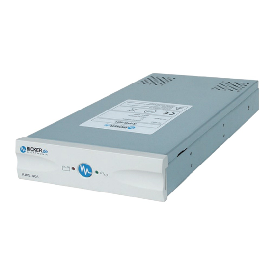
- Seite 2 Benutzerhandbuch IUPS-401-Serie IUPS-401 mit Standard-Frontblende IUPS-401 mit gewechselter, schwarzer Frontblende IUPS-401-Serie Integrierte USV...
-
Seite 3: Inhaltsverzeichnis
Benutzerhandbuch IUPS-401-Serie Allgemein ..................4 Lieferumfang und Lagerung ............4 Systembeschreibung IUPS ............4 Automatische EIN/AUS-Funktion ..........4 Überlastschutz ..................5 Übertemperaturschutz ..............5 Austausch der Frontplatte ............5 Sicherheit ..................6 Einbauanweisung ............... 7 IUPS-401/-B5/-BB/-BC ..............7 IUPS-401-B1/-B4/-BA/-B9/-110-B7 ........10 Bediendisplay ................ -
Seite 4: Allgemein
Benutzerhandbuch IUPS-401-Serie 1. Allgemein 1.1 Lieferumfang und Lagerung Überprüfen Sie sofort nach Erhalt Ihrer IUPS ob Liefer schäden vorliegen. Eine beschädigte Verpackung kann ein Anzeichen hierfür sein. Im Lieferumfang enthalten sind: 1 USV-Gerät IUPS | 1 Netzkabel | 1 schwarze Frontplatte | 1 Benutzerhandbuch Bei IUPS-401/-B5/-BB/-BC: 1 Slotblech mit USB-Platine 1 internes USB-Kabel... -
Seite 5: Überlastschutz
Benutzerhandbuch IUPS-401-Serie 1.4 Überlastschutz Der Laststrom wird von der IUPS überwacht. Bei Überlast während des Batterie betriebs schaltet die IUPS ab. Bei Überlastung im Netzbetrieb ist ein Dauerton zu hören, der bei Beseitigung der Überlast erlischt. 1.5 Übertemperaturschutz Die interne Temperaturüberwachung signalisiert eine auftretende Übertemperatur durch die rote LED und eine akustische Warnung. -
Seite 6: Sicherheit
Benutzerhandbuch IUPS-401-Serie 2. Sicherheit Bitte beachten Sie die Einbauanweisung und nachfolgende Sicherheitshinweise. Der Einbau und Anschluss der IUPS darf nur durch eine qualifizierte Elektrofachkraft erfolgen. Die einschlägigen Regeln der Elektrotechnik sind zu beachten. Die USV- Geräte dürfen nur mit der beiliegenden Netzanschlussleitung betrieben werden. Die IUPS ist nur für den Einbau und Betrieb in einem Gehäuse zugelassen. -
Seite 7: Einbauanweisung
Benutzerhandbuch IUPS-401-Serie 3. Einbauanweisung 3.1 Modelle IUPS-401/-B5/-BB/-BC Durch den Einbau der IUPS in den Rechner an einer Stelle mit möglichst niedriger Temp- eratur erlangen Sie eine Optimierung der Batterielebensdauer. Vor Beginn der Arbeit: Netzstecker ziehen! DSUB9-Verbindungskabel an der Rückseite der IUPS-401 anstecken und dort verschrauben. -
Seite 8: Externe Usb-Anbindung
Benutzerhandbuch IUPS-401-Serie Externe USB-Anbindung Das Verbindungskabel der IUPS- 401 auf die 5-polige Stiftleiste und das Netzkabel der IUPS-401 am Slotblech aufstecken. Das USB-Kabel vom Slotblech zum externen USB-Port stecken. Die Netzverkabelung vom Slot-blech zum Netzteil und Netzstecker verkabeln. Die USB-Datenleitung muss zur Netzverkabelung ca. 5 cm Abstand haben! -
Seite 9: Interne Usb-Anbindung
Benutzerhandbuch IUPS-401-Serie Interne USB-Anbindung Das Verbindungskabel der IUPS-401 auf die 5-polige Stift- leiste aufstecken und das interne USB-Kabel von der 4-poligen Stiftleiste auf das Mainboard stecken. USB-Verkabelung Bitte überprüfen Sie die PIN- Belegung des internen USB- Kabels mit der PIN-Belegung auf Ihrem Mainboard. -
Seite 10: Iups-401-B1/-B4/-Ba/-B9/-110-B7
Benutzerhandbuch IUPS-401-Serie 3.2 Modelle IUPS-401-B1/-B4/-BA/-B9/-110-B7 Durch den Einbau der IUPS in den Rechner an einer Stelle mit möglichst niedriger Temp- eratur erlangen Sie eine Optimierung der Batterielebensdauer. Vor Beginn der Arbeit: Netzstecker ziehen! 1. Netzstecker abziehen 2. Slotblech mit 5-pol. Steuerkabeleinbauen 3. -
Seite 11: Bediendisplay
Benutzerhandbuch IUPS-401-Serie 4. Bediendisplay TEST TEST TEST „Netzbetrieb“-LED: Die grüne LED leuchtet, wenn die Netzspannung anliegt. Die grüne LED blinkt bei Batterieladung. TEST „Back-up-Betrieb“-LED: Die rote LED blinkt, sobald die Netzspannung abgefallen ist und die IUPS die Stromversorgung übernommen hat. Der akustische Alarm TEST ertönt alle 3 Sekunden. -
Seite 12: Schnittstelle Und Software
Benutzerhandbuch IUPS-401-Serie 5. Schnittstelle und Software 5.1 Modelle IUPS-401/-B5/-BB/-BC Die Schnittstelle an der Rückseite der IUPS kann über das im Lieferumfang enthaltene Spezialkabel (mit Platine) mit der USB-Schnittstelle des Computers verbunden werden. Durch die Installation der Software (UPSilon 2000), 1. kann bei Netzausfall eine Warnmeldung am Monitor angezeigt werden 2. - Seite 13 Benutzerhandbuch IUPS-401-Serie ANMERKUNG: Maximale Belastung der Optokoppler: +35 V DC / 150 mA (nicht-induktiv) Die Pins 4 und 7 können mit Masse (Ground) verbunden werden, müssen jedoch gegenüber den Pins 2, 5 und 6 mit negativerem Potential beschalten sein. Die Handbücher „UPSilon 2000“ bzw. „RUPS2000/RUPS2000-B1“ mit aktueller Software-Beschreibung finden Sie auf www.bicker.de...
-
Seite 14: Fehlerbehebung
Benutzerhandbuch IUPS-401-Serie 6. Fehlerbehebung Fehler: Obwohl der Computer angeschlossen und eingeschaltet ist, zeigt die IUPS keine Funktion oder Alarm Möglicher Grund: Fehler bei der Installation Behebungsvorschlag: 1. Netzstecker ziehen 2. Überprüfen der gesamten Installation gemäß Anleitung Fehler: Keine der LEDs leuchtet Möglicher Grund: 1. - Seite 15 Benutzerhandbuch IUPS-401-Serie Fehler: USB-Schnittstelle wird zeitweise in UPSilon deaktiviert Möglicher Grund: USB-Kabel wurde möglicherweise an Netzverkabelung befestigt. Netzstörungen stören die USB-Verbindung. Behebungsvorschlag: USB-Kabel ca. 5 cm von Netzverkabelung verlegen. Fehler: Obwohl am Stromnetz angeschlossen, schaltet der Ausgang der USV nicht durch Möglicher Grund: Batterie stark entladen oder defekt Behebungsvorschlag: Die USV lädt die Batterie und gibt nach Ladung den Ausgang...
-
Seite 16: Technische Daten
Benutzerhandbuch IUPS-401-Serie 7. Technische Daten 7.1 Modelle IUPS-401/-B1/-B4/-B5/-B9/-BA/-BB/-BC T e c h n i s c h e D a t e n Leistung 400 VA / 240 W Eingangsspannung 230 V AC ±15 % Eingangsfrequenz 50 / 60 Hz ±5 % Ausgangsspannung 230 V AC ±15 % Ausgangsfrequenz... -
Seite 17: Iups-401/-B1/-B4/-B5/-B9/-Ba/-Bb/-Bc
Benutzerhandbuch IUPS-401-Serie Modellübersicht IUPS-401/-B1/-B4/-B5/-B9/-BA/-BB/-BC Artikel- Schnittstelle Lastsensor USV-Management-Software Nummer Abschaltung IUPS-401 ≤33 W* UPSilon 2000 und internes USB-Verbin- dungskabel im Lieferumfang enthalten IUPS-401-B5 ≤20 W* (Windows® 7, 8, 10, Server 2012/2016/2019). Externes USB-Kabel 2.0, A-/B-Stecker/500 IUPS-401-BB ≤8 W* mm im Lieferumfang enthalten. IUPS-401-BC ≤0 W* Reboot-Funktion... - Seite 18 Benutzerhandbuch IUPS-401-Serie 7.2 Modell IUPS-401-110-B7 T e c h n i s c h e D a t e n Leistung 400 VA / 240 W Eingangsspannung 110 V AC ±15 % Eingangsfrequenz 50 / 60 Hz ±5 % Ausgangsspannung 110 V AC ±15 % Ausgangsfrequenz 50 / 60 Hz ±1 %...
-
Seite 19: Usv-Management-Software
Benutzerhandbuch IUPS-401-Serie Modellübersicht IUPS-401-110-B7 Artikel- Schnittstelle Lastsensor USV-Management-Software Nummer Abschaltung IUPS-401-110-B7 SERIELL (D-SUB) ≤33 W* RUPS 2000 OEM, USV-Management- Software im Lieferumfang enthalten. Reboot-Funktion Kehrt während eines Netzausfalls und der schon eingeleiteten Shutdown-Phase von Windows® die Netz- spannung wieder zurück, so schaltet die USV nach Ablauf der Shutdown-Zeit den PC aus und nach ca. 5 Sek. in Verbindung mit RUPS 2000 und einem ACPI-PC wieder ein. - Seite 20 User’s Manual IUPS-401-Series IUPS-401 with standard front panel IUPS-401 with changed, black front panel IUPS-401 series Integrated UPS...
- Seite 21 User’s Manual IUPS-401-Series General..................... 22 Contents of Delivery and Storage........22 Functional Description IUPS-401 .......... 22 Automatic ON / OFF Function ..........22 Overload Protection ..............23 Overtemperature Protection ..........23 Replacement of front panel ............. 23 Safety ..................24 Installation Instruction ............
-
Seite 22: General
User’s Manual IUPS-401-Series 1. General 1.1 Contents of Delivery and Storage Please check immediately upon reception whether the delivery is damaged in any way, for which packing damage may be an indication. The contents of delivery are: 1 UPS unit IUPS | 1 Mains cable | 1 black front panel | 1 User‘s Manual IUPS-401/-B5/-BB/-BC: 1 Slot bracket with USB PCB 1 internal USB cable 1 external USB cable 2.0, A-/B-plug / 500 mm... -
Seite 23: Overload Protection
User’s Manual IUPS-401-Series 1.4 Overload Protection Load current is monitored by the IUPS. In case of an overload during battery mode the IUPS switches off. In case of an overload during mains mode a permanent sound is gene- rated, which will stop when the overload is eliminated. 1.5 Overtemperature Protection When an overtemperature is detected by the internal temperature control, this is indica- ted by the red LED and an acoustic alarm sound. -
Seite 24: Safety
User’s Manual IUPS-401-Series 2. Safety Please observe the installation instruction and the following safety warnings. Installation and connection of the IUPS must only be carried out by a qualified electrical technician. The relevant rules of electrical engineering must be observed. For powering the UPS units only the included power cord must be used. -
Seite 25: Installation Instruction
User’s Manual IUPS-401-Series 3. Installation Instruction 3.1 IUPS-401/-B5/-BB/-BC To optimize the service life of the battery install the IUPS into the computer at a location with preferably low temperature. Disconnect mains before starting the installation! Connect DSUB9 connection cable at the back of the IUPS and fasten screws. - Seite 26 User’s Manual IUPS-401-Series External USB connection Connect the connection cable of the IUPS-401 to the 5-pole pin-and-socket connector and the mains cable of the IUPS-401 to the slot bracket. Connect the USB cable from the slot bracket to the external USB port.
-
Seite 27: Usb Connection
User’s Manual IUPS-401-Series Internal USB connection Connect the connection cable of the IUPS-401 to the 5-pole pin and socket connector and the internal USB cable from the 4-pole pin-and-socket connector to the mainboard. USB connection Please compare the pin assignment of the internal USB cable to the pin assign- ment of your PC mainboard. -
Seite 28: Iups-401-B1/-B4/-Ba/-B9/-110-B7
User’s Manual IUPS-401-Series 3.2 IUPS-401-B1/-B4/-BA/-B9/-110-B7 To optimize the service life of the battery install the IUPS into the computer at a location with preferably low temperature. Disconnect mains before starting the installation! 1. Disconnect mains 2. Install slot bracket with 5-pole control cable 3. -
Seite 29: Display
User’s Manual IUPS-401-Series 4. Display TEST TEST TEST “Mains mode“ LED: The green LED is on when mains voltage is supplied. The green LED flashes during battery charge. TEST “Back-up mode“ LED: Combined with an acoustic alarm sound every 3 seconds the red LED flashes as soon as the IUPS has taken over power supply in case of mains TEST power failure. -
Seite 30: Interface And Software
User’s Manual IUPS-401-Series 5. Interface and Software 5.1 IUPS-401/-B5/-BB/-BC The interface at the back of the IUPS can be connected to the USB interface of the com- puter via a special cable (with PCB) which is included in delivery. When the software (UPSilon 2000) is installed, 1. - Seite 31 User’s Manual IUPS-401-Series NOTE: Maximal load of optocouplers: +35 V DC / 150 mA (not inductive) Pins 4 and 7 can be connected to Ground, however, they must be wired with a more negative potential as compared to Pins 2, 5 and 6. The User‘s Manuals „UPSilon 2000“...
-
Seite 32: Troubleshooting
Benutzerhandbuch IUPS-401-Serie 6. Troubleshooting Failure: Although the computer is connected and switched on, the IUPS shows neither function nor alarm Possible cause: Wrong installation Possible countermeasure: 1. Disconnect mains 2. Check the whole installation according to the instruction Failure: None of the LEDs is on Possible cause: 1. - Seite 33 Benutzerhandbuch IUPS-401-Serie Failure: USB interface temporary disabled in UPSilon Possible cause: USB cable maybe is fastened on AC cabling. Interference on AC main disrupts the USB connection. Possible countermeasure: Lay USB cable approx. 5 cm from the mains wiring. Failure: Although connected to the mains, the UPS output does not switch through Possible cause:...
-
Seite 34: Product Specifications
User’s Manual IUPS-401-Series 7. Product Specifications 7.1 Models IUPS-401/-B1/-B4/-B5/-B9/-BA/-BB/-BC T e c h n i c a l d a t a Output power 400 VA / 240 W Input voltage 230 V AC ±15 % Input frequency 50 / 60 Hz ±5 % Output voltage 230 V AC ±15 % Output frequency... -
Seite 35: Iups-401/-B1/-B4/-B5/-B9/-Ba/-Bb/-Bc
User’s Manual IUPS-401-Series Model overview IUPS-401/-B1/-B4/-B5/-B9/-BA/-BB/-BC Article Interface Load sensor UPS management software switch off IUPS-401 ≤33 W* UPSilon 2000 and internal USB cable inclu- ded in delivery (Windows® 7, 8, 10, Server IUPS-401-B5 ≤20 W* 2012/2016/2019). External USB cable 2.0, A-/B-plug / 500 mm included in delivery. - Seite 36 User’s Manual IUPS-401-Series 7.2 Model IUPS-401-110-B7 T e c h n i c a l d a t a Output power 400 VA / 240 W Input voltage 110 V AC ±15 % Input frequency 50 / 60 Hz ±5 % Output voltage 110 V AC ±15 % Output frequency...
-
Seite 37: Iups-401-110-B7
User’s Manual IUPS-401-Series Model overview IUPS-401-110-B7 Article Interface Load sensor UPS management software switch off IUPS-401-110-B7 SERIAL (D-SUB) ≤33 W* RUPS 2000 OEM, UPS management software, included in delivery. Reboot function If mains voltage returns after a power failure while Windows® is already shutting down, the UPS switches the PC off (after the shut-down period) and switches it on again after approximately 5 seconds in conjunction with RUPS 2000 and an ACPI-PC. - Seite 38 User’s Manual IUPS-401-Series Notizen / Notes...
- Seite 39 User’s Manual IUPS-401-Series Notizen / Notes...
- Seite 40 Bicker Elektronik GmbH Ludwig-Auer-Straße 23 86609 Donauwörth · Germany Tel. +49 (0) 906 70595-0 +49 (0) 906 70595-55 Irrtümer und technische Änderungen vorbehalten. Windows® ist ein eingetragenes Warenzeichen der Firma Microsoft Corp. E-Mail info@bicker.de Subject to errors and technical modifications.