Werbung
Quicklinks
Balluff Network Interface IO-Link
Montageanleitung / Installation Guide
BNI IOL-75x-V08-K007
BNI IOL-75x-V09-K007
BNI IOL-75x-V10-K007
BNI IOL-75x-V11-K007
BNI IOL-75x-V13-K007
BNI IOL-75x-V13-K007-008
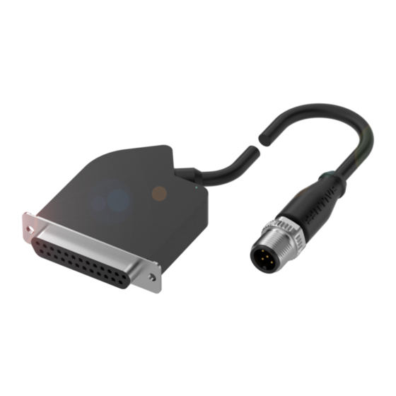
Modulübersicht / Module overview
Diese Montageanleitung ersetzt nicht die Bedienungsanleitung. Für eine
ordnungsgemäße Installation und Betrieb lesen Sie bitte die
Bedienungsanleitung und die dazugehörigen Sicherheitshinweise
sorgfältig durch.
Diese finden Sie zum Download unter http://www.balluff.de.
Bitte wenden Sie sich bei weiteren Fragen an unseren Kundenservice.
These Installation Guide do not replace the User´s Guide. For proper
installation and operation, please read the User´s Guide and associated
safety instructions carefully.
This is ready for you to download at http://www.balluff.com.
For any further question please contact our Customer Service.
Modulübersicht / Module overview
1
2
3
1
Status LED "UA"
2
Status LED "COM"
3
Anschluss Ventilinsel /
Connector Valve Block
Ventilinselstecker/
Valve Block Connector
FESTO MPA, Bosch Rexroth, LSH 04,
BNI IOL-75x-V08-K007
max 24 Ventile/Valves
FESTO CPV, LSH 04, max 16 Ven-
BNI IOL-75x-V09-K007
tile/Valves
SMC VQC 1000/2000/4000, max.
BNI IOL-75x-V10-K007
24 Ventile/Valves
SMC VQC 1000/2000/4000, max.
BNI IOL-75x-V11-K007
16 Ventile/Valves
BNI IOL-75x-V13-K007(-008) Numatics max. 22 Ventile/Valves
Mechanische Anbindung / Mechanical connections
Das Modul BNI IOL-75x... wird direkt an der Ventilinselbaugruppe mit
dem D-Sub Stecker verschraubt. Eine weitere mechanische Befesti-
gung ist nicht vorgesehen.
The module BNI IOL-75x-... is directly mounted at D-Sub 25 pin
connector at the valve block unit. A additional mechanical fixation is
not necessary.
www.balluff.com
max 24 Ventile/Valves, Masse/Ground Pin 25
max 16 Ventile/Valves, Masse/Ground Pin 25
max. 24 Ventile/Valves, Masse/Ground Pin 13
max. 16 Ventile/Valves, Masse/Ground Pin 13
max. 22 Ventile/Valves, Masse/Ground Pin 23 + 24
max. 22 Ventile/Valves, Masse/Ground Pin 23 + 24
5
4
4
Anschlussleitung /
Cable
5
Anschluss IO-Link /
Connector IO-Link
Ventilinsel/Valve Block Unit
Elektrische Verbindungen / Electrical connection
Die Ventilinselstecker benötigen keinen separaten Versorgungs-
spannungsanschluss. Die Bereitstellung der Versorgungs-
spannung erfolgt über Pin 1 des M12 Steckers durch die über-
geordnete IO-Link Masterbaugruppe.
The valve block connector has no separate power supply
connection. The supply of the power comes from the IO-Link
master unit at pin 1 and pin 2 of the M12 male connector.
IO-Link Interface
M12 A-coded
Pin BNI IOL 750-... BNI IOL 751-... BNI IOL 752-...
1
US, UA
2
-
GND US,
3
GND UA
4
C/Q
5
-
Versorgungsspannung Modul, +24V /
US
Power Supply Module, +24V
Versorgungsspannung Aktoren, +24V /
UA
Power Supply Actuators, +24V
Massebezug zu Versorgungsspannung Modul /
GND US
Ground reference to Power Supply Module
Massebezug zu Aktorspannung /
GND UA
Ground reference to Power Supply Actuators
Kommunikationsleitung IO-Link /
C/Q
IO Link communication line
Schnittstelle Ventilinselbaugruppe / Interface Valve Block Unit
D-Sub, 25-polig, Buchse / D-Sub, 25-pole, female
BNI IOL-
BNI IOL-
Pin
75x-V08..
75x-V09..
1
V. 1 S. A
V. 1 S. A
2
V. 1 S. B
V. 1 S. B
3
V. 2 S. A
V. 2 S. A
4
V. 2 S. B
V. 2 S. B
5
V. 3 S. A
V. 3 S. A
6
V. 3 S. B
V. 3 S. B
7
V. 4 S. A
V. 4 S. A
8
V. 4 S. B
V. 4 S. B
9
V. 5 S. A
V. 5 S. A
10
V. 5 S. B
V. 5 S. B
11
V. 6 S. A
V. 6 S. A
12
V. 6 S. B
V. 6 S. B
13
V. 7 S. A
V. 7 S. A
14
V. 7 S. B
V. 7 S. B
15
V. 8 S. A
V. 8 S. A
16
V. 8 S. B
V. 8 S. B
17
V. 9 S. A
-
18
V. 9 S. B
-
19
V. 10 S. A
-
20
V. 10 S. B
-
21
V. 11 S. A
-
22
V. 11 S. B
-
23
V. 12 S. A
-
24
V. 12 S. B
-
25
GND
GND
V = Ventil / Valve
S = Spule / Coil
US
US
UA
UA
GND US,
GND US
GND UA
C/Q
C/Q
-
GND UA
BNI IOL-
BNI IOL-
BNI IOL-
75x-V10..
75x-V11..
75x-V13..
V. 1 S. A
V. 1 S. A
V. 1 S. A
V. 2 S. A
V. 2 S. A
V. 1 S. B
V. 3 S. A
V. 3 S. A
V. 2 S. A
V. 4 S. A
V. 4 S. A
V. 2 S. B
V. 5 S. A
V. 5 S. A
V. 3 S. A
V. 6 S. A
V. 6 S. A
V. 3 S. B
V. 7 S. A
V. 7 S. A
V. 4 S. A
V. 8 S. A
V. 8 S. A
V. 4 S. B
V. 9 S. A
V. 5 S. A
-
V. 10 S. A
V. 5 S. B
-
V. 11 S. A
V. 6 S. A
-
V. 12 S. A
V. 6 S. B
-
GND
GND
V. 7 S. A
V. 1 S. B
V. 1 S. B
V. 7 S. B
V. 2 S. B
V. 2 S. B
V. 8 S. A
V. 3 S. B
V. 3 S. B
V. 8 S. B
V. 4 S. B
V. 4 S. B
V. 9 S. A
V. 5 S. B
V. 5 S. B
V. 9 S. B
V. 6 S. B
V. 6 S. B
V. 10 S. A
V. 7 S. B
V. 7 S. B
V. 10 S. B
V. 8 S. B
V. 8 S. B
V. 11 S. A
V. 9 S. B
-
V. 11 S. B
V. 10 S.B
-
GND
V. 11 S. B
-
GND
V. 12 S. B
-
-
1
Werbung

Verwandte Anleitungen für Balluff BNI IOL-75x-V08-K007 Serie


Inhaltszusammenfassung für Balluff BNI IOL-75x-V08-K007 Serie
- Seite 1 User´s Guide and associated IO-Link Interface safety instructions carefully. This is ready for you to download at http://www.balluff.com. M12 A-coded Pin BNI IOL 750-… BNI IOL 751-… BNI IOL 752-… For any further question please contact our Customer Service.
- Seite 2 Balluff Network Interface IO-Link Funktionsanzeige / Function indicators Technische Daten / Technical data Dimension Module status Status Funktion / Function Mechanische Daten / Mechanical data An / Aktorversorgung ok / Gehäusematerial / Kunststoff, Macromelt 6208 / Actuator power supply ok...