peerless-AV SP735P Montageanleitung
Inhaltsverzeichnis
Verfügbare Sprachen
Verfügbare Sprachen
Quicklinks
Installation and Assembly:
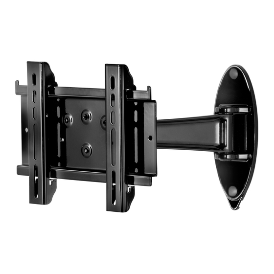
SmartMount™ Pivoting Wall Arm for 10" - 26" Flat Panel
Displays
Models:
SP735P, SP735P-S
Max UL Load Capacity: 25 lb (11.3 kg)
2300 White Oak Circle • Aurora, Il 60502 • (800) 865-2112 • Fax: (800) 359-6500 • www.peerlessmounts.com
ISSUED: 02-15-10 SHEET #: 095-9316-2 08-02-11
Downloaded from
www.Manualslib.com
manuals search engine
Inhaltsverzeichnis

Verwandte Anleitungen für peerless-AV SP735P


Inhaltszusammenfassung für peerless-AV SP735P
- Seite 31 Anbringung und Zusammenbau: SmartMount™-LCD-Wandhalterung mit Schwenken Flachbildschirme von 10 - 26 Zoll Modelle: SP735P, SP735P-S Maximale UL Tragfähigkeit: 25 lb (11.3 kg) 2300 White Oak Circle • Aurora, Il 60502 • (800) 865-2112 • Fax: (800) 359-6500 • www.peerlessmounts.com AUSGEGEBEN: 02-15-10 BLATT NR.: 095-9316-2 08-02-11 Downloaded from www.Manualslib.com...
-
Seite 32: Für Den Zusammenbau Erforderliche Werkzeuge
Deutsch HINWEIS: Lesen Sie die gesamte Anleitung, bevor Sie mit der Anbringung und dem Zusammenbau beginnen. ACHTUNG • Beginnen Sie mit der Anbringung Ihres Peerless-Produkts erst, nachdem Sie die in dieser Montageanleitung enthaltenen Anleitungen und Achtungshinweise gelesen und sich gründlich mit ihnen vertraut gemacht haben. Falls Sie Fragen hinsichtlich irgendeiner der Anleitungen oder Achtungshinweise haben, wenden Sie sich in den USA bitte an den Peerless-Kundendienst unter der Rufnummer 1-800-865-2112. -
Seite 33: Teileliste
Deutsch Vergewissern Sie sich vor Beginn der Arbeiten, dass alle dargestellten Teile mit Ihrem Produkt mitgeliefert wurden. Teileliste SP735P SP735P-S Beschreibung Anz. Teile Nr. Teile Nr. A Wandhalter 095-P1965 095-4965 B Adapterhalterungen 095-P1944 095-4644 C Nr. 14 x 2,5 Zoll Flachkopf-... -
Seite 34: Anbringung An Wänden Mit Einer Holzständerreihe
Deutsch Anbringung an Wänden mit einer Holzständerreihe ACHTUNG • Bei der Anbringung muss darauf geachtet werden, dass die Wand die kombinierte Last von Bildschirm und allen Befestigungsteilen und -komponenten tragen kann. • Ziehen Sie die Schrauben fest genug an, dass die Wandplatte sicher befestigt ist, doch ohne sie zu überdrehen. Durch Überdrehen können die Schrauben beschädigt werden, wodurch ihr Haltevermögen stark reduziert wird. -
Seite 35: Anbringung An Massivbeton Oder Porenbetonstein
Anbringung an Massivbeton oder Porenbetonstein Deutsch ACHTUNG • Bei der Anbringung von Peerless-Wandhaltern an Porenbetonstein muss sichergestellt werden, dass die tatsächliche Stärke des Betons, in den das Loch für die Betondübel gebohrt wird, mindestens 35 mm (1 3/8 Zoll) beträgt. Bohren Sie nicht in Mörtelfugen! Achten Sie darauf, dass die Anbringung an einem massiven Teil des Blocks erfolgt, im Allgemeinen mindestens 25 mm (1 Zoll) von der Blockseite entfernt. -
Seite 36: Anbringung Von Kipphalterungen
Deutsch Anbringung von Kipphalterungen ACHTUNG • Ziehen Sie die Schrauben so an, dass die Adapterhalterungen sicher befestigt sind. Ziehen Sie die Schrauben nicht zu fest an. Durch die beim Überdrehen entstehende Spannung können die Schrauben beschädigt werden, was ihr Haltevermögen stark reduziert und möglicherweise dazu führen kann, dass die Schraubenköpfe sich lösen. - Seite 37 Deutsch Bildschirme mit fl acher Rückseite Beginnen Sie mit der kürzesten Schraube und schrauben Sie diese wie unten gezeigt von Hand durch die Mehrlochscheibe und Adapterhalterung in den Bildschirm. Die Schraube muss sich um mindestens drei volle Umdrehungen in die Montagebohrung drehen lassen und gut festsitzen. Nicht zu stark anziehen. Wählen Sie eine längere Schraube aus dem Befestigungsteilesortiment, wenn sich die Schraube nicht um drei volle Umdrehungen in den Bildschirm schrauben lässt.
-
Seite 38: Anbringung Und Abnahme Des Flachbildschirms
Anbringung und Abnahme des Flachbildschirms Deutsch ACHTUNG • Ziehen Sie immer eine zusätzliche Person heran oder verwenden Sie mechanische Hebegeräte, um den Flachbild- schirm sicher zu heben und zu positionieren. Haken Sie die Adapterhalterungen (B) an der Wandhalter (A) ein. Drehen Sie die Sicherheitsschrauben mit Hilfe eines Inbusschlüssels für Kreuzschlitzschraubendreher mindestens sechs Mal nach rechts, um ein... -
Seite 39: Kabelführung
Deutsch Kabelführung Die Kabel können mithilfe der Kabelbinder (I) verlegt werden. Befestigen Sie den Kabelbinderanker (J) wie in Abbildung 5.1 dargestellt mithilfe der 8-32 x 1/4 Zoll Kreuzschlitzschraube (K) an der Ober- oder Unterseite des Wandarms (A). Befestigen Sie die Kabel mithilfe von Kabelbindern (I) wie in Abbildung 5.2 dargestellt an der Ober- oder Unterseite des Wandarms (A). -
Seite 40: Aeinstellung Der Armspannung
Deutsch Aeinstellung der Armspannung ACHTUNG • Die Schraube darf nicht entfernt bzw. soweit gelöst werden, dass sie nicht mehr in den Halter eingreift, da anson- sten der Bildschirm herabfallen kann. • Ziehen Sie die Schrauben wie erforderlich nach, falls sie mit der Zeit locker werden. Das maximale Drehmoment zum Festziehen der Schrauben darf 5,6 Nm (50 in•lbs) nicht überschreiten. - Seite 42 Français GARANTIE DE CINQ ANS Peerless Industries, Inc. (« Peerless ») garantit aux utilisateurs fi naux d’origine des produits Peerless que lesdits produits ne présenteront aucun défaut de matériau ou de main-d’œuvre, dans la mesure où ils sont utilisés normalement, pendant une période de cinq ans à compter de la date d’achat par l’utilisateur fi nal d’origine (mais en aucun cas plus de six ans après la date de fabrication du produit).