Vimar Well-contact Plus 01522 Montageanweisungen
Quicklinks
Well-contact Plus
01522
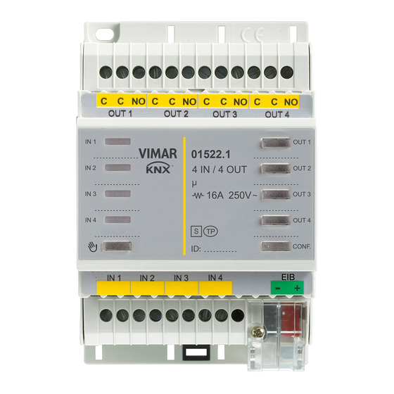
Dispositivo di ingresso/uscita, standard KNX, 4 uscite a relè 16
A 250 V~, 4 ingressi, installazione su guida DIN (60715 TH35),
occupa 4 moduli da 17,5 mm.
Il dispositivo consente la gestione di 4 ingressi e 4 uscite generiche per applicazioni
tipiche nel terziario (accesso ad uffici, camere d'ospedale o di hotel, piscine, saune,
impianti sportivi, spazi riservati, ecc.).
Il dispositivo è provvisto di 4 ingressi ON/OFF e di 4 uscite a relè da 16 A 250 V~.
CARATTERISTICHE.
• Tensione di alimentazione: BUS 29 V SELV.
• Assorbimento: 10 mA.
• Potenza dissipata: 4 W.
• 4 ingressi digitali per contatti NO o NC (privi di potenziale, SELV).
• Uscite a relè 16 A 250 V~
• Carichi comandabili a 250 V~:
- carichi resistivi: 16 A (20.000 cicli);
- lampade ad incandescenza: 10 A (20.000 cicli);
- lampade fluorescenti e lampade a risparmio energetico: 1 A (20.000 cicli);
e trasformatori elettronici: 4 A (20.000 cicli);
- trasformatori ferromagnetici: 10 A (20.000 cicli);
- motori cos
0,6: 3,5 A (100.000 cicli);.
• Morsetti:
- bus TP;
- contatti relè (C, NO);
- ingressi digitali.
• Configurazioni relè: monostabile e bistabile.
• Temperatura di funzionamento: -5 °C - +45 °C (uso interno).
• 4 moduli da 17,5 mm.
FUNZIONAMENTO.
La configurazione del dispositivo, dell'indirizzo fisico, dei parametri (ingressi contatti
NO o NC, uscite relè normali o temporizzate, interblocco logico delle quattro uscite
a relè, ecc.) avviene mediante il software ETS.
Nel caso in cui nel dispositivo di ingresso/uscita venga caricato un applicativo ETS
non corretto, il led rosso lampeggerà (errore di "device type").
Per ripristinare la configurazione desiderata, caricare nel dispositivo l'applicativo
ETS corretto.
Attenzione: Se si inibisce la forzatura manuale delle uscite OUT, queste mantengo-
no il loro stato attuale fino ad un successivo messaggio di comando che proviene
dal BUS.
Avvertenza per l'utilizzo dell'interblocco logico delle uscite
I parametri Stato all'inizio dello stato di blocco / Stato al fine dello stato di bloc-
co, relativi all'oggetto ETS denominato Blocco, interagiscono con la funzione di
interblocco logico; pertanto, se si utilizza l'oggetto Blocco, l'interblocco logico
delle uscite non può essere garantito.
Importante: La lunghezza del cavo per il collegamento degli ingressi non deve
superare i 30 m.
REGOLE DI INSTALLAZIONE.
L'installazione deve essere effettuata con l'osservanza delle disposizioni regolanti l'in-
stallazione del materiale elettrico in vigore nel paese dove i prodotti sono installati.
Le quattro uscite a relè (out 1, out 2, out 3 e out 4) sono separate tra loro mediante
un isolamento funzionale a 250 V~ e non da un doppio isolamento; pertanto, ad
esempio, non collegare un circuito SELV ad un'uscita che sia adiacente ad un'altra
connessa alla rete di alimentazione a 230 V~.
Il circuito di alimentazione delle uscite a relè deve essere protetto contro le sovra-
correnti da un dispositivo, fusibile con potere di interruzione nominale di 1500 A o
un interruttore automatico tipo C, con corrente nominale non superiore a 16 A.
CONFORMITÀ NORMATIVA.
Direttiva BT.
Direttiva EMC.
Norma EN 50090-2-2, EN 50428.
Viale Vicenza, 14 - I 36063 Marostica VI
Tel. +39 0424 488 600 - Fax (Italia) +39 0424 488 188 - Fax (Export) +39 0424 488 709
www.vimar.eu
Input/output device, KNX standard, 4 relay outputs 16 A 250
V~, 4 inputs, installation on DIN rail (60715 TH35), occupies 4
modules sized 17.5 mm.
This device enables managing 4 inputs and 4 generic outputs for typical applications
in the tertiary sector (entry to offices, hospital or hotel rooms, swimming pools, sau-
nas, sports facilities, reserved spaces, etc.).
The device is equipped with 4 ON/OFF inputs and 4 relay outputs of 16 A 250 V~.
CHARACTERISTICS.
• Supply voltage: BUS 29 V SELV.
• Absorption: 10 mA.
• Dissipated power: 4 W.
• 4 digital inputs for NO or NC contacts (with no potential, SELV).
• Relay outputs 16 A 250 V~
• Controllable loads at 250 V~:
- resistive loads: 16 A (20,000 cycles);
- incandescent lamps: 10 A (20,000 cycles);
- fluorescent lamps and energy saving lamps: 1 A (20,000 cycles);
and electronic transformers: 4 A (20,000 cycles);
- ferromagnetic transformers: 10 A (20,000 cycles);
- motors cos 0.6: 3.5 A (100,000 cycles).
• Terminals:
- TP bus;
- relay contacts (C, NO);
- digital inputs.
• Relay configurations: one-position stable and two-position stable.
• Operating temperature: -5 °C - +45 °C (inside).
• 4 modules of 17.5 mm.
OPERATION.
The configuration of the device, physical address and parameters (NO or NC
contacts inputs, normal or timed relay outputs, logical interlocking of the four relay
outputs, etc.) takes place through the ETS software.
If the input/output device is loaded with an incorrect ETS application, the red LED
will flash ("device type" error).
To restore the desired configuration, load the device with the correct ETS appli-
cation.
Important: If you inhibit manual forcing of the OUT outputs, they will keep their cur-
rent status until the next command message from the BUS.
Warning for using the logical interlock of the outputs
The parameters of the State at the start of the state of block/State at the end of
the state of block, related to the ETS item called Block, interact with the function
of logical interlocking; therefore, if using the Block object, the logical interlock of the
outputs cannot be guaranteed.
Important: The length of the cable for connecting the inputs must not exceed 30 m.
INSTALLATION RULES.
Installation should be carried out in compliance with the current regulations regarding
the installation of electrical systems in the country where the products are installed.
The four relay outputs (out 1, out 2, out 3 and out 4) are separated from each
other by functional insulation at 250 V~ and not by double insulation; therefore,
for instance, do not connect a SELV circuit to an output adjacent to another one
connected to the power supply mains at 230 V~.
CONFORMITY.
LV directive.
EMC directive.
Standard EN 50090-2-2, EN 50428.
Istruzioni
Instruction sheet
49400226B0 01 1105
VIMAR - Marostica - Italy

Verwandte Anleitungen für Vimar Well-contact Plus 01522


Inhaltszusammenfassung für Vimar Well-contact Plus 01522
- Seite 1 Norma EN 50090-2-2, EN 50428. Viale Vicenza, 14 - I 36063 Marostica VI Tel. +39 0424 488 600 - Fax (Italia) +39 0424 488 188 - Fax (Export) +39 0424 488 709 49400226B0 01 1105 www.vimar.eu VIMAR - Marostica - Italy...
- Seite 2 Normes EN 50090-2-2, EN 50428. NS-Richtlinie. EMV-Richtlinie. Norm EN 50090-2-2, EN 50428. Viale Vicenza, 14 - I 36063 Marostica VI Tel. +39 0424 488 600 - Fax (Italia) +39 0424 488 188 - Fax (Export) +39 0424 488 709 www.vimar.eu...
- Seite 3 ΣΥΜΜΟΡΦΩΣΗ ΜΕ ΤΑ ΠΡΟΤΥΠΑ. Οδηγία BT. Οδηγία ΗΜΣ. Πρότυπα EN 50090-2-2, EN 50428. Viale Vicenza, 14 - I 36063 Marostica VI Tel. +39 0424 488 600 - Fax (Italia) +39 0424 488 188 - Fax (Export) +39 0424 488 709 www.vimar.eu...
- Seite 4 VISTA FRONTALE E COLLEGAMENTI - FRONT VIEW AND CONNECTIONS - VUE FRONTALE ET RACCORDEMENTS FRONTANSICHT UND ANSCHLÜSSE - VISTA FRONTAL Y CONEXIONES - ΜΠΡΟΣΤΙΝΗ ΠΛΕΥΡΑ ΚΑΙ ΣΥΝΔΕΣΕΙΣ. OUT 1 OUT 2 OUT 3 OUT 4 IN 1 IN 2 IN 3 IN 4 ITALIANO ENGLISH...