Werbung
REQUIRED TOOLS
AND MATERIALS:
• 2 People
• Tape Measure
• Wood Board (scrap)
• Sawhorse or Support
Table
• Hammer
• Tape
• Safety Glasses
• Phillips Screwdriver
• Scissors
• (2 each) Wrenches and/or
Socket Wrenches and Sockets
(Deep-Well Sockets are
Recommended).
3/8"
1/2"
9/16"
3/4"
AND/OR
3/8"
1/2"
9/16"
3/4"
• Extension is Recommended.
• Garden Hose or Sand
• Step Ladder - 8 ft. (2.4 m)
OPTIONAL TOOLS
AND MATERIALS:
• Large & Small Adjustable
Wrenches
© COPYRIGHT 2005 by SPALDING
Portable System
Owners Manual
Customer Service Center
• N53 W24700 South Corporate Circle • Sussex, WI 53089 • U.S.A.
WARNING!
READ AND UNDERSTAND
OPERATOR'S MANUAL
BEFORE USING THIS UNIT.
FAILURE TO FOLLOW
OPERATING INSTRUCTIONS
COULD RESULT IN INJURY
OR DAMAGE TO
PROPERTY.
Toll-Free Customer Service Number for U.S: 1-800-558-5234,
For Canada: 1-800-284-8339,
For Europe: 00 800 555 85234 (Sweden: 009 555 85234),
For Australia: 1-800-632 7921
Internet Address: http://www.huffysports.com
1
Write Model Number
From Box Here:
04/06
ID#
M6011141
Werbung
Inhaltsverzeichnis

Verwandte Anleitungen für Huffy Sports M6011141


Inhaltszusammenfassung für Huffy Sports M6011141
- Seite 1 Toll-Free Customer Service Number for U.S: 1-800-558-5234, • Large & Small Adjustable For Canada: 1-800-284-8339, Wrenches For Europe: 00 800 555 85234 (Sweden: 009 555 85234), For Australia: 1-800-632 7921 Internet Address: http://www.huffysports.com 04/06 M6011141 © COPYRIGHT 2005 by SPALDING...
-
Seite 2: Before You Start
• See instruction manual for proper installation and maintenance. Not all items pictured are included with every model. In the U.S.: 1-800-334-9111 In the U.S.: 1-800-772-5346 In the U.S.: 1-800-558-5234 In the U.S.: 1-888-713-5488 Canada: 1-800-284-8339 ID#: 556790 05/05 M6011141 04/06... -
Seite 3: Safety Instructions
• Climate, corrosion or misuse could result in system failure. • If technical assistance is required, contact Huffy Sports. • Minimum operational height is 6’6” (1.98m) to the bottom of backboard. - Seite 4 NOTICE TO ASSEMBLERS ALL Huffy Sports Basketball Systems, including those used for DISPLAYS, MUST be assembled and ballasted with sand or water according to the instructions. Failure to follow instructions could result in SERIOUS INJURY. It is NOT acceptable to devise a makeshift weight system.
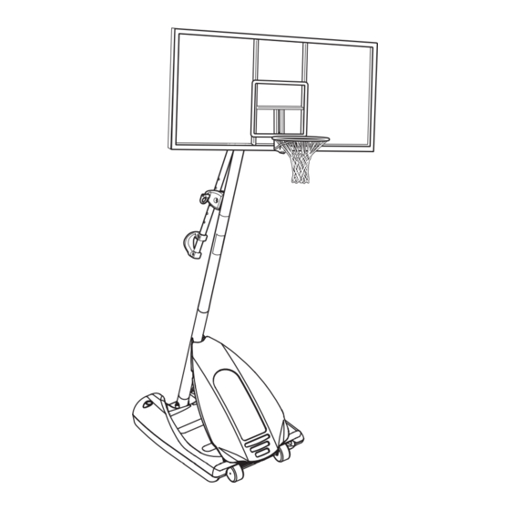
- Seite 5 Get to know the basic parts of your basketball system... FRONT BACK BACKBOARD TOP POLE ELEVATOR ASSEMBLY BOTTOM POLE MIDDLE POLE FRONT STRUTS COVER BASE WHEEL CARRIAGE ASSEMBLY 04/06 M6011141...
- Seite 6 204859 Cover, Pin Slide HARDWARE IDENTIFIER (NUTS, WASHERS & METAL SPACERS) Item #30 (4) Item #14 (2) Item #11 (15)* Item #31 (4) Item #21 (7) Item #43 (2) Item #47 (6)* Item #50 (4) Item #10 (18)* M6011141 04/06...
- Seite 7 Item #19 (1) Item #55 (1) Item #57 (6) Item #22 (2) Item #46 (6) HARDWARE IDENTIFIER (PLASTIC SPACERS & CAPS) Item #53 (4) Item #17 (1) Item #7 (2) Item #20 (8) Item #56 (4) Item #24 (2) 04/06 M6011141...
- Seite 8 HARDWARE IDENTIFIER (OTHER) Item #61 (1) Item #44 (1) Item #45 (1) Item #46 (1) Item #48 (1) Item #47 (1) M6011141 04/06...
- Seite 9 3-1/2" (9 CM) TOGETHER, THE POLE SECTIONS MINIMUM SHOULD HAVE A 3-1/2" MINIMUM OVERLAP. OVERLAP, LEAVING 1-1/2" BETWEEN THE OVERLAPPING POLE AND THE IDENTIFICATION STICKER. IDENTIFICATION STICKER POLE IDENTIFICATION 5" MARK IDENTIFICATION STICKER 1-1/2" WOOD SCRAP (NOT SUPPLIED) 04/06 M6011141...
- Seite 10 RODS SHOWN ARE FOR VISUAL REPRESENTATION OF ALIGNMENT AND ARE NOT SUPPLIED WITH THE HARDWARE IMPORTANT! Holes in top (1) and bottom (3) pole sections MUST align to correctly position elevator WOOD SCRAP system toward playing (NOT SUPPLIED) surface. M6011141 04/06...
- Seite 11 SECTION B: ASSEMBLE THE BASE This is what your system will look like when you’ve finished this section: TOOLS REQUIRED FOR THIS SECTION (2) 1/2” AND/OR 1/2” 04/06 M6011141...
- Seite 12 TWO PEOPLE REQUIRED FOR THIS PROCEDURE. FAILURE TO FOLLOW THIS WARNING COULD RESULT IN SERIOUS INJURY AND/OR PROPERTY DAMAGE. IMPORTANT! THE CUT CORNERS OF THE POLE BRACKET NEED TO FACE TOWARD THE BACK OF THE BASE AS SHOWN. M6011141 04/06...
- Seite 13 WARNING COULD RESULT IN SERIOUS INJURY AND/OR PROPERTY DAMAGE. IMPORTANT! Rotate non-secured ends of tank struts (16) outward to mounting holes in tank as shown.Secure ends of tank struts (16) to tank as shown. Repeat for opposite side. 04/06 M6011141...
- Seite 14 Insert axle (5) through wheel bracket (4). Secure wheels (6) to axle using pushnuts (7). Carefully tap pushnuts onto axle with hammer or mallet IMPORTANT! SIDE OF WHEEL WITH LONGER PLASTIC AXLE NEEDS TO FACE THE WHEEL BRACKET. Install wheel assembly to base (8) using bolts(9), washers(10) and nuts (11) as shown. M6011141 04/06...
- Seite 15 SECTION C: ASSEMBLE THE ELEVATOR & BACKBOARD This is what your system will look like when you’ve finished this section: TOOLS REQUIRED FOR THIS SECTION (1) 3/8”, (2) 1/2”, (2) 9/16” and (2) 3/4” AND/OR 3/8” 1/2” 3/4” 9/16” 04/06 M6011141...
- Seite 16 Install pole mount bracket (28) and reinforcement bracket (18) with carriage bolts (22) as shown. Tighten flange nuts (11) completely. Attach spacers (24, 43) to pole mount bracket (28) with bolts (29), washers (50), and lock nuts (31) as shown. IMPORTANT! Tighten just until washers (50) stop moving. M6011141 04/06...
- Seite 17 (59, 60) to adjustment rod with screw (55), carriage bolts (54), and flange nuts (11) as shown. IMPORTANT! Indicator labels should be applied as close to holes as possible to prevent labels from being damaged during height adjustment. 04/06 M6011141...
- Seite 18 Insert handle assembly through pole mount assembly as shown. Lock pole assembly in place at the 10’ (3.05 m) mark with pin (27). Assemble backboard brackets (52) using bolts (29), and nuts (30) as shown. NOTE ORIENTATION M6011141 04/06...
- Seite 19 Attach lower elevator tubes (34) and counter balance spring (36) to backboard support brackets (52) using spacers (53 & 56), bolt (57), and nut (21) as shown. Insert T-bolt (48) into rim bracket (61) then, attach that assembly to board using bolts (41) and nuts (21) 04/06 M6011141...
- Seite 20 Attach upper elevator tubes (33) to backboard support brackets (52) using spacers (53), bolt (57), and nut (21) as shown. IMPORTANT! Tighten ALL Hardware from Steps 6-8 After this Assembly is Completed. M6011141 04/06...
- Seite 21 Install upper elevator tubes (33) to triangle plates (45) as shown. Install handle assembly to lower elevator tubes (34) using bolt (57), spacers (20), and nut (21) as shown. NOTE: Before going on to next step, set adjustable system assembly to the 10’ (3.05 m) setting. 04/06 M6011141...
- Seite 22 B. Install reinforcement bracket (44) onto T-bolt (48) as shown. C. Install spring (46) onto T-bolt (48) as shown. D. Install special nut (47) and washer (45) onto T-bolt (48). E. Tighten special nut (47) until flush with end of T-bolt (48). NOTE: ORIENTATION OF BRACKET M6011141 04/06...
- Seite 23 Insert bolt (57) through left side upper elevator tube (33), then stretch spring (36) onto bolt (57). Insert bolt (57) through right side upper elevator tube (33) and secure with nut (21). WARNING! USE EYE PROTECTION WHEN INSTALLING SPRINGS. NOTE: Peel protective film from surface of acrylic backboard prior to use. 04/06 M6011141...
- Seite 24 INJURY AND/OR PROPERTY DAMAGE. WARNING! DO NOT LEAVE ASSEMBLY UNATTENDED WHEN EMPTY; IT MAY TIP OVER. CAUTION ADD TWO GALLONS (7.6 LITERS) OF NON-TOXIC ANTIFREEZE IN SUB-FREEZING CLIMATES. NOTE IF USING SAND: 2 GALLONS OF ANTI-FREEZE IS NOT REQUIRED M6011141 04/06...
-
Seite 25: Front Cover
Install front cover (38) by lining up stand-offs along the tank struts. Insert a tie strap (39) through the top two and bottom two stand offs. Wrap tie straps around tank struts as shown and secure tightly. Trim excess of tie strap as shown in FIG.A. STANDOFFS FIG. A 04/06 M6011141... - Seite 26 511679 05/05 A. While holding handle, remove pin (27). B. Move elevator up or down to desired height. C. Replace pin (27) full length to lock system at desired height. WARNING! DO NOT ALLOW CHILDREN TO ADJUST HEIGHT. M6011141 04/06...
- Seite 27 Anrufer in Europa: 00 800 555 85234 (Schweden: 009 555 85234) Für Australien: 1-800-333.061 - Internet-Adresse: http://www.huffysports.com Número telefónico gratuito de servicio al cliente en EE. UU.: 1-800-558-5234, para Canadá: 1-800-284-8339, para Europa: 00 800 555 85234 (Suecia: 009 555 85234), para Australia: 1-800-333 061 - Dirección en Internet: http://www.huffysports.com 04/06 M6011141...
- Seite 28 Position drehen. que quede en posición vertical. 5. Vérifiez la stabilité du système. 5. Die Stabilität des Systems 5. Revise la estabilidad del überprüfen. sistema. GE511679 05/05 SP511679 05/05 FR511679 05/05 M6011141 04/06...
- Seite 29 Pruebe el ajuste de los pernos grandes en los orificios grandes de los tubos elevadores, soportes del respaldo y placas triangulares. Cuidadosamente muévalos en círculos para eliminar cualquier exceso de pintura, si es necesario. HINWEIS: Nicht jedem Modell sind alle abgebildeten Teile beigepackt. 04/06 M6011141...
- Seite 30 M6011141 04/06...
-
Seite 31: Consignes De Sécurité
Klimatische Bedingungen, Korrosion oder Fehlgebrauch kann zu Systemdefekten führen. Technische Unterstützung kann direkt von Huffy Sports angefordert werden. Die Mindestspielhöhe beträgt 1,98m (6,6 Fuß) bis zur Unterkante der Korbwand. Die meisten Verletzungen werden durch einen Fehlgebrauch bzw. ein Missachten der Anleitungen verursacht. -
Seite 32: Hinweis Für Die Personen, Die Den Zusammenbau Durchführen
AVIS AUX PERSONNES CHARGÉES DU MONTAGE TOUS les systèmes de basket-ball Huffy Sports, y compris ceux utilisés en EXPOSITION, DOIVENT être assemblés et lestés de sable ou d'eau, selon les instructions. Suivez ces instructions sous peine d'encourir des BLESSURES GRAVES. Il est INACCEPTABLE de composer un système de lestage de fortune. - Seite 33 SECTION DE POTEAU CENTRALE VERLÄNGERUNGSBAUGRUPPE MITTLERES STANGENTEIL SECCIÓN MEDIA DEL POSTE CONJUNTO DEL ELEVADOR AVANT ABDECKUNG SECTION DE POTEAU INFÉRIEURE BORDE UNTERES STANGENTEIL CONTREFICHES SECCIÓN INFERIOR DEL POSTE STREBEN PUNTALES SOCLE BASE BASE CHARIOT RÄDERGRUPPE CONJUNTO DEL CARRO PORTAMUELA 04/06 M6011141...
- Seite 34 Griff, links 204855 Poignée gauche 204856 Griff, rechts 204856 Poignée droite 900033 Slam Jam-Halterung, schwarz 900033 Support Slam Jam, noir * Diesem Modell können zusätzliche Teile beigepackt sein. * Des pièces supplémentaires sont peut-être fournies avec ce modèle. M6011141 04/06...
- Seite 35 Perno, fijación 204832 Soporte, montaje del poste 206360 Perno, cabeza hexagonal, 3/8-16 x 2.625 * Puede haber piezas adicionales en este modelo. 203063 Contratuerca, 5/16-18 201124 Contratuerca, 3/8-16 900867 Placa triangular 904807 Tubo elevador, superior-corto 900183 Tubo elevador, inferior-largo 04/06 M6011141...
- Seite 36 #14 (2) #11 (15)* #31 (4) #21 (7) #43 (2) #47 (6)* #50 (4) #10 (18)* IDENTIFICATION DES PIÈCES (AUTRES) BEFESTIGUNGSTEILESCHLÜSSEL (SONSTIGE) IDENTIFICADOR DE HERRAJE (OTROS) #44 (1) #61 (1) #45 (1) #46 (1) #48 (1) #47 (1) M6011141 04/06...
- Seite 37 #55 (1) #46 (6) #22 (2) IDENTIFICATION DES PIÈCES (ENTRETOISES ET CAPUCHONS EN PLASTIQUE) BEFESTIGUNGSTEILESCHLÜSSEL (PLASTIK-ABSTANDSSTÜCKE UND KAPPEN) IDENTIFICADORES DEL HERRAJE (ESPACIADORES DE PLÁSTICO Y TAPAS) #53 (4) #17 (1) #7 (2) #20 (8) #24 (2) #56 (4) 04/06 M6011141...
- Seite 38 ¡NO SE PUEDEN separar! enthalten) Die Stangenteile müssen einander um mindestens 9 cm (3 ½ Zoll) überlappen. Nach Trozo de madera dem Zusammenbau können die einzelnen (No se suministra) Stangenteile NICHT mehr voneinander getrennt werden. M6011141 04/06...
- Seite 39 Los orificios de las secciones superior (1) e dem Zusammenbau können die einzelnen enthalten) inferior (3) del poste DEBEN estar alineados Stangenteile NICHT mehr voneinander getrennt werden. para colocar correctamente el sistema elevador hacia la superficie de juego. Trozo de madera (No se suministra) 04/06 M6011141...
- Seite 40 So sieht das System aus, wenn Sie mit diesem Bauabschnitt fertig sind: Así es como se verá su sistema cuando haya terminado esta sección: OUTILS REQUIS POUR CETTE SECTION FÜR DIESEN BAUABSCHNITT BENÖTIGTES WERKZEUG HERRAMIENTAS REQUERIDAS PARA ESTA SECCIÓN (2) 1/2” UND/ODER ET/OU 1/2” M6011141 04/06...
- Seite 41 SI NO SE OBSERVA ESTA LAS ESQUINAS ADVERTENCIA SE PODRÍA OCASIONAR UNA RECORTADAS DEL lesión GRAVE Y/O DAÑOS A LA PROPIEDAD. SOPORTE DEL POSTE NECESITAN ESTAR ORIENTADAS HACIA LA PARTE POSTERIOR DE LA BASE COMO SE MUESTRA. 04/06 M6011141...
- Seite 42 Haga girar los extremos no asegurados de los puntales del tanque (16) hacia fuera hasta los orificios de montaje del tanque como se muestra. Fije los extremos de los puntales del tanque (16) en el tanque como se muestra. Repita el procedimiento en el lado opuesto. M6011141 04/06...
- Seite 43 (11), de la façon illustrée. Den Rädergruppe wie gezeigt mit Schrauben (9), Unterlegscheiben (10) und Mutter (11) am Sockel (8) befestigen. Instale el conjunto de la rueda en la base (8) usando pernos (9), arandelas (10) y tuercas (11) como se muestra. 04/06 M6011141...
- Seite 44 Así es como se verá su sistema cuando haya terminado esta sección: OUTILS REQUIS POUR CETTE SECTION FÜR DIESEN BAUABSCHNITT BENÖTIGTES WERKZEUG HERRAMIENTAS REQUERIDAS PARA ESTA SECCIÓN (1) 3/8”, (2) 1/2”, (2) 9/16”, (2) 3/4” UND/ODER ET/OU 3/8” 1/2” 3/4” 9/16” M6011141 04/06...
- Seite 45 (44) no se muevan. IMPORTANT! WICHTIG! ¡IMPORTANTE! Serrez juste jusqu'à ce que les rondelles (50) cessent de tourner. Nur so weit anziehen, bis sich die Unterlegscheiben (50) nicht mehr bewegen. Apriete lo suficiente para que las arandelas (50) no se muevan. 04/06 M6011141...
- Seite 46 Öffnungen angebracht werden, um eine Beschädigung der Aufkleber während der Höhenverstellung zu vermeiden. Las etiquetas indicadoras se deben aplicar tan cerca de los orificios como sea posible para evitar que sean dañadas durante los ajustes de altura. M6011141 04/06...
- Seite 47 Placez les supports de panneau (52) entre les contrefiches du panneau, comme illustré. Die Korbwandklammern (52) wie gezeigt zwischen die Korbwandverstrebungen einsetzen. Coloque los soportes del respaldo (52) entre los puntales del respaldo como se muestra. NOTEZ L'ORIENTATION. DIE KORREKTE AUSRICHTUNG BEACHTEN. NOTE LA ORIENTACIÓN. 04/06 M6011141...
- Seite 48 Baugruppe mit Schrauben (41) und Muttern (21) an der Korbwand befestigen. Introduzca el perno en T (48) en el soporte del borde (61), y luego monte ese conjunto en el tablero usando pernos (41) y tuercas (21). M6011141 04/06...
- Seite 49 Die oberen Verlängerungsrohre (33) wie gezeigt mit Abstandsstücken (46 & 56), Schraube (57) und Mutter (21) an den Korbwandstützklammern (52) befestigen. Conecte los tubos elevadores superiores (33) en los soportes del respaldo (52) usando espaciadores (46 & 56) pernos (57) y tuercas (21) como se muestra. 04/06 M6011141...
- Seite 50 à 3,05 m (10 pi). Bevor zum nächsten Schritt übergegangen wird, ist das Einstellsystem auf die 3,05-m- (10-Zoll)-Markierung einzustellen. Antes de continuar con el siguiente paso, coloque el conjunto del sistema ajustable a una altura de 3,05 m (10'). M6011141 04/06...
- Seite 51 C. Instale el resorte (57) en el perno T (55) como se muestra. D. Instale la tuerca especial (58) y la arandela (45) en el perno T (55). E. Apriete la tuerca (58) hasta que quede al ras del extremo del perno T (55). 04/06 M6011141...
- Seite 52 M6011141 04/06...
- Seite 53 Décollez le film de protection HINWEIS: de la surface du panneau en acrylique avant usage. NOTA: Vor Gebrauch die Schutzfolie von der Oberfläche der Akryl- Korbwand abziehen. Desprenda la película protectora de la superficie del respaldo de acrílico antes de usarlo. 04/06 M6011141...
- Seite 54 HINWEIS NOTA SI VOUS UTILISEZ DU SABLE : L'UTILISATION DE 4 LITRES D'ANTIGEL EST INUTILE. BEI VERWENDUNG VON SAND: KEINE ZUSÄTZLICHEN 7,6 L (2 GAL) GEFRIERSCHUTZMITTEL EINFÜLLEN. SI SE USA ARENA: NO SE REQUIERE EL USO DE ANTICONGELANTE M6011141 04/06...
- Seite 55 (39) a través de los dos separadores superiores y de los dos separadores inferiores. Envuelva las correas de sujeción alrededor de los puntales del tanque como se muestra y fije firmemente. Recorte el exceso de la correa de sujeción como se muestra en la FIG. A. SÉPARATEURS DISTANZELEMENTE SEPARADORES FIG.A ABB. A 04/06 M6011141...
- Seite 56 A. Mientras sujeta la manija, quite el pasador (27). B. Mueva el elevador hacia arriba o hacia abajo a la altura deseada. C. Vuelva a colocar el pasador (27) a toda su longitud para fijar el sistema a la altura deseada. M6011141 04/06...