Hafele Dialock DFT V2 Montageanleitung
Möbelterminal
Inhaltsverzeichnis
Verfügbare Sprachen
Verfügbare Sprachen
Quicklinks
Montageanleitung
Installation instructions
Instructions d'assemblage
Instrucciones de montaje
Istruzioni di montaggio
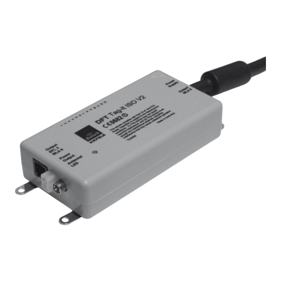
Dialock Möbelterminal DFT V2
Dialock Furniture Terminal DFT V2
Dialock Terminal de Meuble DFT V2
Dialock Terminal de Mueble DFT V2
Dialock Terminale per Mobili DFT V2
Montageanleitung - Deutsch .................................... 2
Installation instructions - English............................ 6
Instructions de montage - Français....................... 10
Instrucciones de montaje - Español ...................... 14
Istruzioni di montaggio - Italiano ........................... 18
gilt für Artikel:
applies to Art. No.:
valable pour référence:
adecuado para N° de ref.:
valido per codice:
237.58.111
1
Inhaltsverzeichnis

Verwandte Anleitungen für Hafele Dialock DFT V2


Inhaltszusammenfassung für Hafele Dialock DFT V2
-
Seite 1: Inhaltsverzeichnis
Montageanleitung Installation instructions Instructions d’assemblage Instrucciones de montaje Istruzioni di montaggio gilt für Artikel: Dialock Möbelterminal DFT V2 applies to Art. No.: Dialock Furniture Terminal DFT V2 valable pour référence: adecuado para N° de ref.: Dialock Terminal de Meuble DFT V2 valido per codice: 237.58.111 Dialock Terminal de Mueble DFT V2... -
Seite 2: Montageanleitung - Deutsch
Montageanleitung - Deutsch Hinweise zu dieser Montageanleitung Inhalt und Zielgruppe Die Beachtung dieser Montageanleitung ist unerlässlich für die erfolgreiche und gefahrlose Montage des der Anleitung Produkts. Alle vorgegebenen Montageschritte, Anweisungen und Hinweise beachten! Diese Montageanleitung richtet sich an: den Betreiber des Produkts, •... -
Seite 3: Begriffserklärung
Montagebedingungen Abstand zwischen zwei Antennen (intern oder extern) • mindestens 25 cm Biegeradius beim Verlegen der Kabel • maximal 5 cm HINWEIS Produktschäden durch Kondenswasser auf kalten Komponenten! > Vor der Montage sicherstellen, dass alle Produktkomponenten Umgebungstemperatur haben! > Produkte schon einige Zeit vor der Montage am Montageort lagern. Festlegen der In dieser Montageanleitung wird die Montage anhand einer beispielhaften Situation dargestellt Montageposition... -
Seite 4: Anschlussübersicht
Montagebeschreibung WARNUNG Lebensgefährlicher Stromschlag bei Montage mit eingestecktem Netzstecker! Die gesamte Montage muss stromlos erfolgen! > Während der Montage nie den Netzstecker in die Steckdose stecken. > Auch nach Abschluss der Montage nicht den Netztstecker einstecken. Dadurch wird so- fort die “Erste Inbetriebnahme” gestartet. >... -
Seite 5: Maßzeichnung
Klemme 3, 4: Betriebsart. Ist hier eine Brücke gesetzt, so arbeitet das DFT V2 nach der Inbetriebnahme oder nach einem Reset in der Betriebsart "Fallenschloss". Ist keine Brücke gesetzt, arbeitet das DFT V2 nach Inbetriebnahme oder einem Reset in der Betriebsart "Riegelschloss". Klemme 5 Masse Klemme 6+7, 8+9:... - Seite 22 Anschlussplan - gleichschließend Wiring diagram - keyed alike Schéma de raccordement - s'entrouvrant Esquema de conexión - cierres iguales Schema di collegamento - chiusura uguale PS1 / PS 2 max. 11 Output Power EFL 3 Supply MLA 6 Output Power Output MLA8 Antenna/ EFL 3...
- Seite 23 Anschlussplan - Mischbetrieb gleichschließend, einzeladressierbar Wiring diagram - mixed mode: keyed-alike, individually addressable Schéma de raccordement - Mode mixte s'entrouvrant, adressage individuel Esquema de conexión - modo mixto: cierres iguales, direccionable individualmente Schema di collegamento - funzionamento misto: chiusura uguale, indirizzamento individuale PS1 / PS2 EFL 3 EFL 3...
- Seite 24 Montage PS1 / PS 2 Installation PS1 / PS 2 Montage PS1 / PS 2 Montaje PS1 / PS 2 Montaggio PS1 / PS 2...
- Seite 25 Montage DFT Installation DFT Montage DFT Montaje DFT Montaggio DFT 3,5 x 15...