Herunterladen Inhalt Inhalt Diese Seite drucken
VMB TL-075 Bedienungsanleitung
Vorschau ausblenden Andere Handbücher für TL-075:

Werbung

Verfügbare Sprachen

Verfügbare Sprachen

ES
EN
DE
TL-075 /
TL-078
TORRE ELEVADORA
TOWERLIFT
TRAVERSENLIFT
MANUAL DE INSTRUCCIONES
OPERATING INSTRUCTIONS USER MANUAL
BEDIENUNGSANLEITUNG
V.08.19

Werbung

Inhaltsverzeichnis
loading

Inhaltszusammenfassung für VMB TL-075

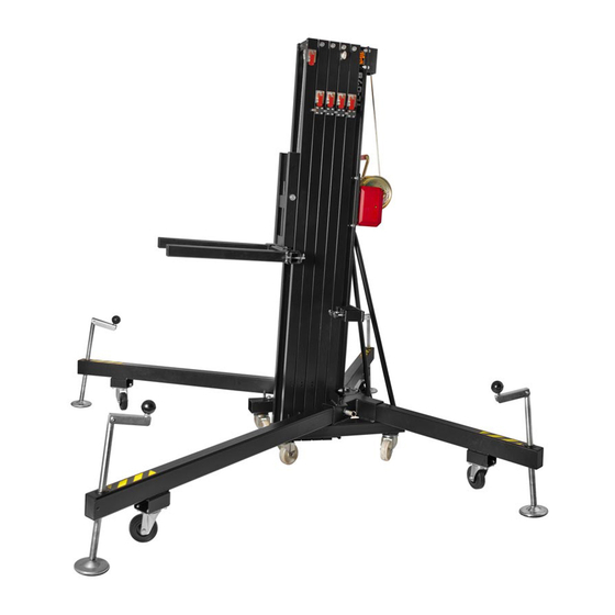
  • Seite 1 TL-075 / TL-078 TORRE ELEVADORA TOWERLIFT TRAVERSENLIFT MANUAL DE INSTRUCCIONES OPERATING INSTRUCTIONS USER MANUAL BEDIENUNGSANLEITUNG V.08.19...
  • Seite 2: Made In Spain (Eu)

    TL-075 / TL-078 TRAVERSENLIFT TL-075 / TL-078 CONTENTS / ÍNDICE Features of the TL-075/78 / Características TL-075/78....... 3 - 4 English Quick operation guide..............5 - 11 Manual de usuario Español................12 - 19 Bedienungsanleitung Deutsch..............20 - 26 Sketches / Planos piezas................27 - 37 Spare part list / Lista de repuestos..............
  • Seite 3 TL-075 / TL-078 S: Transport compartment / Alojamiento de transporte T: Transport wheels / Ruedas de transporte PRO LIFTS S.L. Depósito legal y copyright 2014. Todos los derechos reservados.
  • Seite 4 TL-075 / TL-078 ALS-C: ALS-1: ALS-2: ALS-3: ALS-4: Handle / Manivela Spirit level Leg / Pata Stabilizer / Estabilizador SRS: Sequence Retainer System Winch / Cabrestante ALS-C ALS-1 ALS-2 ALS-3 ALS-4 PRO LIFTS S.L. Depósito legal y copyright 2014. Todos los derechos reservados.
  • Seite 5 1. INTRODUCTION 2.4 - Minimum load: 25 Kg (55 lb). Dear customer, in order to ensure a safe and reliable operation of the TL-075 / TL- 2.5 - Security : ALS 078 towerlift please follow the instructions 2.6 - Maximum height : the lift, read the instructions completely TL-075: 6.5 m (21.3’).
  • Seite 6 2.18 - Swivel wheels to transport the lift when folded. 3. SAFETY PRECAUTIONS. 3.1 - The TL-075 / TL-078 is a machine designed to elevate loads upwards in a vertical direction, It should NEVER be used as a platform to elevate people.
  • Seite 7 ENGLISH 3.5 - P) are placed and set-up co- rrectly with their safety pins (R 3.6 - NEVER use the lift on a vehicle or any other mobile surface. 3.7 - If there is a possibility of strong winds or gusts, use of straps.
  • Seite 8 3.11 - Do not use stepladders on the lift or use it as a support for them. 3.12 - faulty cables, always change them if there is any doubt. Only use VMB steel cables; reference: DIN 3060. 3.13 - placed in its transport position, before transportation. 3.14 - a special heat and pressure resistant solution.
  • Seite 9 4.5 - DO NOT OVERLOAD THE LIFT. different height. For this reason it is ne- MAXIMUM LOAD IS 300 kg (667 lb) TL-075 cessary that the structure does not stretch MAXIMUM LOAD IS 280 kg (617 lb) TL-078 The lift should NEVER be overloaded.
  • Seite 10 ALS ALS-1) out. This releases the bloc- Security system ALS / ILS The TL-075 & TL-078 incorporates the ), whilst maintaining the ALS patented security system ALS (Automatic (ALS-2, ALS-3, ALS-4 & ALS-C) should position it is left in.
  • Seite 11: Transport

    Only use VMB steel cables reference: DIN cur, produced through defect material or 3060 torsion resistant.
  • Seite 12: Información Técnica

    2. Información técnica. 3. Precauciones de seguridad. 2. INFORMACIÓN TÉCNICA 4. Instrucciones de uso. 5. Mantenimiento. 2.1 - Torre elevadora TL-075 / TL-078. 2.2 - Diseñada para levantar estructuras, 1. INTRODUCCIÓN trusses e iluminación en sentido vertical a diferentes alturas.
  • Seite 13: Precauciones De Seguridad

    2.14 - Patas estabilizadoras ajustables porte de la torre cuando este plegada. 3. PRECAUCIONES DE SEGURIDAD 3.1 - La torre elevadora TL-075 / TL-078 es una máqu- na diseñada para la elevación de cargas en dirección vertical. NUNCA se debe utilizar como plataforma elea- vadora de personas.
  • Seite 14 Manual de usuario ESPAÑOL 3.4 - Este elevador NUNCA debe utilizarse para elevar una carga que no ha sido correctamente revisada. Es necesario da en el soporte de elevación apropiado para que el peso de la carga sólo actúe en una dirección vertical. 3.5 - Comprobar que las patas (P) estén situadas correcta- R) los cuales deben estar introducidos y bloqueados.
  • Seite 15 El cable no debe contener hilos rotos o mostrar signos de áreas aplastadas/aplanadas. NUNCA use cables defectuosos, siempre debe cambiarlos si hay alguna duda. Utilice solamente cable de acero VMB torsión. 3.13 - Antes de transportar la torre, todos los tramos deben ser bajados, y las patas deben extraerse y colocarse en su posición de transporte.
  • Seite 16 O R I G I N A L 4. INSTRUCCIONES DE USO. 4.5 - LA CARGA MÁXIMA PARA TL-075 ES 300 kg (661 lb). 4.1 - Coloque el elevador sobre una su- TL-078 ES 280 kg (617 lb) La torre elevadora NUNCA debe ser so- jo sirviendose de las ruedas direccionales brecargada.
  • Seite 17 Sistema de seguridad ALS / ILS Esquema 4.6.1 El TL-075 y TL-078 incorporan el sistema de seguridad patentado ALS (bloqueo Distancia del Carga máxima automático de seguridad). Este sistema...
  • Seite 18 Manual de usuario ESPAÑOL 4.8 - Bloqueo: los ALS rojos desbloqueados. Debe des- La torre puede dejarse en cualquier po- cender completamente cada tramo antes sición intermedia si se requiere. Una vez de empezar a bajar el siguiente. el sistema esta elevado hasta la altura NUNCA tire de otro ALS rojo sin haber deseada tan solo deje de girar la mani- bajado completamente el tramo anterior.
  • Seite 19 Los daños cabo por un distribuidor autorizado VMB causados por un uso inadecuado, modi- estado general de todos los elementos de terceros o incendio accidental no están elevación y sistemas de seguridad que in-...
  • Seite 20 Durchmesser: Ø6 mm selbst vormimmt. 2.13 - Ausleger mit verstellbaren Spindeln 2. TECHNISCHE DATEN. 2.14 2.1 - Hebeturm, Typ TL-075 / TL-078. Sicherheitsrastbolzen. 2.2 - 2.15 - Wasserwaage zum Einstellen der PRO LIFTS S.L. Depósito legal y copyright 2014. Todos los derechos reservados.
  • Seite 21: Korrosionsschutz Und Veredelung

    (optional TL–054/056) 3. SICHERHEITSMAßNAHMEN. 3.1 - Beförderung von Personen. 3.2 - Achten Sie darauf, das der TL-075 / TL-078 Tower auf festem, geraden Untergrund steht. Und vergewissern Sie Position zum Boden eingenommen hat.Bei Bedarf mittels entsprechende Tunlage einstellen. 3.3 - überschritten werden...
  • Seite 22: Es Ist Nicht Gestattet Den Lift Auf Einem Fahrzeug Mit

    Bedienungsanleitung DEUTSCH 3.5 - Vergewissern Sie sich, dass die Ausleger richtig ein- 3.6 - Es ist nicht gestattet den Lift auf einem Fahrzeug mit 3.7 - Bei Freiluftanwendungen den Turm auf festen Boden Niemals an Fahrzeugen die Abspannungen befestigen oder 3.8 - Bewegen Sie den Lift niemals unter Belastung.
  • Seite 23 Bedienungsanleitung DEUTSCH 3.11 - Stellen Sie niemals Leitern an den Tower. 3.12 - verwendet werden. 3.13 - Alle Angebauten Teile sind für den Transport einzu- fahren. 3.14- Ölen oder Fetten der Fallbremsen ist zu unterlassen, 3.15 - nicht möglich. 3.16 - Niemals die Winde, oder Teile der Winde unter Be- lastung demontieren.
  • Seite 24: Den Hebeturm Auf Den Transportrollen

    Stellteller ( Q ) durch Drehen der Kurbel ( H ) in entsprechender Richtung Distance from the Maximum load zum Zentrieren der Wasserwaagenblase ( load’s center to TL-075 TL-078 the lifting carriage F ) an der Kreismitte einstellen. 25 cm (0.82’) (661.4 lb)
  • Seite 25: Plazieren Der Ladung

    Bedienungsanleitung DEUTSCH 4.6 - Plazieren der Ladung: 4.7 - Heben: Die Transportsicherung ( O ) entriegeln. Plazieren Sie die Ladung so nah wie Den Lift mittels Drehen der Winde ( W ) möglich in Richtung des Towers. Die Maxi- in Uhrzeigersinn ( N1 ) in die gewünschte nebenstehenden Diagramm.
  • Seite 26: Für Die Bestellung Von Ersatzteilen Ist

    Hülse, das Kurbelgewinde und die Von der garantie ausgenommen sind Abschnitte zu schmieren. Achtung: Die Bremsscheiben nicht einölen oder fetten !!! 5.3 - Der Hebeturm TL-075 / TL-078 sollte 5.4 - sicherheit sind ausschließlich Original BGV-C1 BGG-912 leistungsansprüche sind für den Anwender EC Conformity Declaration pursuant to the aufgehoben, wenn er Nicht- Original –...
  • Seite 27 TL-075 & TL-078 SPARE PARTS SKETCHES / CROQUIS DE LAS PIEZAS DE REPUESTO DE TL-075 y TL-078 Barras..................28-31 Barras TL-075 Barras TL-078 ALS System / Sistema ALS SRS System / Sistema retentor SRS Prisionero cable Cable protector / Protector de cable...
  • Seite 28 TL-075 7589C 7040 7566 7562 7563 7564 7565 PRO LIFTS S.L. Depósito legal y copyright 2014. Todos los derechos reservados.
  • Seite 29 TL-078 7589 7040 7566 7562 7563 7563 7564 7565 PRO LIFTS S.L. Depósito legal y copyright 2014. Todos los derechos reservados.
  • Seite 30 TL-075 7565 7564 7563 7562 7566 7565 7564 7563 7562 7566 PRO LIFTS S.L. Depósito legal y copyright 2014. Todos los derechos reservados.
  • Seite 31 TL-078 7565N 7564 7563 7563 7562 7566 7565N 7564 7563 7563 7562 7566 PRO LIFTS S.L. Depósito legal y copyright 2014. Todos los derechos reservados.
  • Seite 32 2141 2152 Profile 4 (TL-078) Profile 2 (TL-078) Profile 1 Base (TL-078) Profile 3 (TL-075) Profile 3 (TL-078) Profile 2 (TL-075) Profile 1 Base (TL-075) Ref: 7663 Ref: 7663 Ref: 7664 Ref: 7665 7 mm 4 mm 4 mm 4 mm...
  • Seite 33 TL-075 TL-075 / TL-078 7962 2047 4078 4080 4056 4057 4079 2047 2158 2162N 2047x2 2140 7246 7078 2047 2047 2047 2158 7962 2047 4078 7265 7593 7595 2152 7234 7232 2047 2047 2152 7234 3218 3219 7573 (x2) 7246 (x2)
  • Seite 34 TL-075 TL-075 / TL-078 2140 2047 7962 7961 7587 6409 7061 2044 2044 7061 (x2) 2037 PAT-05 2026 MR-PAS 7209 7209D 7078 2141 2152 (x2) PRO LIFTS S.L. Depósito legal y copyright 2014. Todos los derechos reservados.
  • Seite 35 TL-075 TL-075 / TL-078 7852M 7502 7061 7061 7240 2044 7061 2044 3257 3257 7061 2044 2044 7061 7061 7240 7061 2044 3257 7040 7851N PRO LIFTS S.L. Depósito legal y copyright 2014. Todos los derechos reservados.
  • Seite 36 TL-075 TL-075 / TL-078 7566 7872 7242 7242 7243 3250 7518N 7061 7061F 7222N 2044 7244C 7245 7247 3219 7573 7248 7573 PRO LIFTS S.L. Depósito legal y copyright 2014. Todos los derechos reservados.
  • Seite 37 TL-075 TL-075 / TL-078 4021 2170 2170 2170 2170 2044 4021 4021 7061 7061 7061 7811 7240 7240 7814 7812 7504N 7813 7965 7504N 7541 7065 7066 7964 2244 3246 Stabilizer kit TL-075 / TL-078 7242 Ref: 7598 7804 7549...
  • Seite 38 SPARE PARTS LIST / LISTA DE REPUESTOS TL-075 / TL-078 Code Description GB / USA Descripción ES 1540 (B) Desbloqueador sistema SRS (B Negro) 2026 Safety catch 2037 M10x30 Allen screw Tornillo allen M10x30 2044 Tuerca autoblocante M10 2047 M12 Washer...
  • Seite 39 7550 M8 Washer Arandela carrocero M8 7562 (B) Tramo 4 TL-075 / 5 TL-078 (B Negro) 7563 (B) Tramo 3 TL-075 / 3 y 4 TL-078 (B Negro) PRO LIFTS S.L. Depósito legal y copyright 2014. Todos los derechos reservados.
  • Seite 40: Vergessen Sie Nicht Den Modelljahr Der Produktion

    Steel cable Ø6 x 18 m (TL-078) Cable de acero Ø6 x 18 m (TL-078) 7589C Steel cable Ø6 x 16.4 m (TL-075) Cable de acero Ø6 x 16.4 m (TL-075) 7593 Cable protection for Ø90 pulley Protección cable para polea Ø90 7595 Steel Ø90 pulley...
  • Seite 41 PRO LIFTS S.L. Depósito legal y copyright 2014. Todos los derechos reservados.
  • Seite 42 PRO LIFTS S.L. Depósito legal y copyright 2014. Todos los derechos reservados.
  • Seite 44 facebook / vmblifts Canal VMBLifts For further information follow the advise of our technicians: Para más información consulte con nuestros técnicos en: PRO LIFTS S.L. C/ Ciudad de Barcelona Nº19 Pol. Ind. Fuente del Jarro 46988 Paterna (Valencia) Spain Tlf Export: +34 96 171 81 86 Tlf Nacional: 96 171 81 83 email: info@prolifts.es web: www.prolifts.es...

Diese Anleitung auch für:

Tl-078

Inhaltsverzeichnis