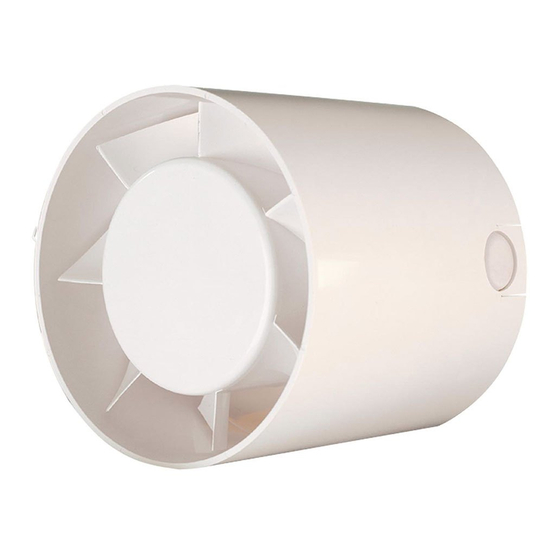
Cata KIT IN LINE MT-100 Einbau- Und Betriebsanleitung
Vorschau ausblenden
Andere Handbücher für KIT IN LINE MT-100:
- Gebrauschsanweisung und wartung (12 Seiten) ,
- Gebrauschsanweisung und wartung (28 Seiten)

Verwandte Anleitungen für Cata KIT IN LINE MT-100


Inhaltszusammenfassung für Cata KIT IN LINE MT-100
- Seite 1 KIT IN LINE MT-100 MT-100 TIMER MT-125 MT-125 TIMER MT-150 MT-150 TIMER INSTRUCCIONES DE USO EINBAU UND BETRIEBSANLEITUNG INSTRUCTIONS D'USAGE USE INSTRUCTIONS ISTRUZIONI D'USO GEBRUIKSAANWIJZING BIJ INSTRUÇÕES DE USO...
- Seite 3 Ref. 60801640.03.02.2005...
-
Seite 4: Instalación
Español INSTALACIÓN A) Este extractor tubular debe ir colocado en conducto rígido o flexible.. B) La distancia de la boca de aspiración hasta la boca de expulsión no debe sobrepasar los 3 mts. de longitud. C) El extractor (C) se colocará entre los puntos A y B (aspiración y expulsión) y se fijará a las tuberías mediante bridas para que quede completamente inmovilizado. -
Seite 5: Conexión Eléctrica
CONEXIÓN ELÉCTRICA Debe conectarse a una red monofásica a la tensión y frecuencia indicadas en la placa de características del extractor. En la instalación debe existir un interruptor omnipolar con una distancia entre contactos igual o superior a 3 mm. 1) Aflojar el tornillo (A) hasta poder retirar la tapa (B). -
Seite 6: Installation
DEUTSCH INSTALLATION A) Dieser röhrenförmige Abzug muß in einer Rohr-oder Schlauchleitung montiert werden. B) Der Abstand zwischen Ansaug- und Aussstoßöffnung darf eine Länge von 3 m nicht überschreiten. C) Der Abzug (C) wird zwischen den Punkten A und B (Ansaugen und Ausstoßen) montiert und mit Flanschen an den Leitungen befestigt, damit er sich nicht mehr bewegen kann. -
Seite 7: Elektrischer Anschluss
ELEKTRISCHER ANSCHLUSS Der Abzug ist an ein Einsphasennetz anzuschließen, dessen Spannung und Frequenz mit den auf dem Typenschild des Abzugs angegebenen Werten übereinstimmen. 1) Lockern Sie die Schraube (A), bis Sie den Deckel (B) abnehmen können. 2) Machen Sie ein Loch in di Bohrlochabdeckung (C), und ziehen Sie die Netzkabel durch. 3) Schließen Sie die Netzkabel an die Klemmen an der Anschlußleiste (D) an. - Seite 8 Português INSTALAÇÃO A) Este extractor tubular deve ir colocado num conduto rígido ou flexível. B) A distância da boca de aspiração à boca de expulsão não deve ser superior a 3 metros de comprimento. C) O extractor (C) será colocado entre os pontos A e B (aspiração e expulsão) e será fixada nos tubos por meio de bridas para que fique completamente imobilizado.
-
Seite 9: Ligação Eléctrica
LIGAÇÃO ELÉCTRICA Deve ser ligado a uma rede monofásica à tensão e frequências indicadas na placa de características do extractor. Na instalação deve existir um interruptor omnipolar com uma distância entre contactos igual ou superior a 3 mm. 1) Afrouxar o parafuso (A) até poder retirar a tampa (B). 2) Perfurar o tapa-furos (C) e passar os fios de alimentação. - Seite 10 FRANÇAIS INSTALLATION A) Cet extracteur tubulaire doit être placé dans un conduit rigide ou flexible . B) La distance comprise entre l’ouverture d’aspiration et celle d’expulsion ne doit pas être supérieure à 3 m. C) L’ extracteur (c) sera placé entre les points A et B (aspiration et expulsion) et sera fixé aux tuyauteries à l’aide de brides pour son immobilisation complète.
-
Seite 11: Connexion Électrique
CONNEXION ÉLECTRIQUE L’extracteur sera connecté à un réseau monophasé, à la tension et à la fréquence indiquées sur la plaque signalétique de l’appareil. Dans l’installation, prévoir un interrupteur omnipolaire avec une distance entre contacts égale ou supérieure à 3 mm. 1) Desserrer la vis (A) jusqu’à... - Seite 12 Nederlands INSTALLATIE A) Deze buisvormige afzuiger dient op een stijve of flexibele buis geplaatst te worden. B) De afstand tussen de luchtinlaat en de luchtuitlaat dient niet meer dan 3 m. te bedragen. C) De afzuiger (C) wordt tussen de punten A en B (inlaat en uitlaat) geplaatst en de buizen worden met klemmen vastgezet zodat ze niet meer kunnen bewegen.
-
Seite 13: Elektrische Aansluiting
ELEKTRISCHE AANSLUITING Dient op een eenfasig lichtnet aansgesloten te worden waarvan de spanning en de frequentie overeenkomen met die die op het typeplaatje aangegeven staan. Bij de installatie dient een veelpolige schakelaar opgenomen te zijn waarvan de afstand tussen de contacten groter of gelijk aan 3 mm moet zijn. - Seite 14 ENGLISH INSTALLATION A) This tubular extractor is designed to be installed in a flexible or rigid conduit. B) The distance between the intake and exhaust openings should not be more than 3 m. C) The extractor (C) is placed between points A and B (intake and exhaust) and fixed to the conduits by clamps that hold it securely in position.
-
Seite 15: Electrical Connection
ELECTRICAL CONNECTION The extractor unit should be connected to a single phase supply network at the voltage and frequency indicated on the extractor characteristics plate. The electrical installation must be fitted with a single-pole switch with a distance between contacts of at least 3 mm. -
Seite 16: Installazione
Italiano INSTALLAZIONE A) Questo aspiratore tubolare deve essere collocato in un condotto rigido o flessible. B) La distanza tra la bocca di aspirazione e la bocca di espulsione non deve superare i 3 metri. C) L’aspiratore (C) dovrà essere collocato tra i punti A e B (aspirazione ed espulsione) e fissato alla tubazione mediante fascette in modo che rimanga completamente immobile. - Seite 17 CABLAGGIO L’apparecchio deve essere collegato ad una rete monofase avente la tensione e la frequenza indicate sulla piatrina delle caratteristiche dell’aspiratore. L’impianto dovrà essere dotato di interruttore onnipolare con una distanza tra i contatti di almeno 3 mm. 1) Svitare la vite (A) quel tanto che basti per poter togliere il corpechio (B). 2) Estrarre il tappo (C) e far passare per il foro i cavi d’alimentazione.
- Seite 18 Fig. 2...
- Seite 19 Fig. 1 ESQUEMAS DE CONEXIONADO • ANSCHLUSS SCHÉMAS DE BRANCHEMENT • CONNECTION LAYOUT SCHEMI DI COLLEGAMENTO • AANSLUITSCHEMA'S ESQUEMAS DAS LIGAÇÕES KIT MT-100 KIT MT-100 TIMER KIT MT-125 KIT MT-125 TIMER Negro / Schwarz Marrón / Braun Noir / Black Luces u otra carga / Leuchtanzeige o.ä.
- Seite 20 CATA ELECTRODOMÉSTICOS, S.L. C. Àngel Guimerà, 16-17 - 08570 TORELLÓ (Barcelona) SPAIN Tel. +34 938 594 100 - Fax +34 938 593 254 www.cata.es · e-mail: cata@cata.es Atención al Cliente: 902 410 450 atencionalcliente@cata.es...