ELCOM REU512Y Bedienungsanleitung
Quicklinks
REU512Y
Video-Modul Einbau 2Draht
Built-in 2-wire camera module
1
(1)
(2) (3)
2
(NU) (NU) (7)
X X L L T T H H
(4)
(5)
(NU)
1
Sicherheitshinweise
Einbau und Montage elektrischer Geräte dürfen
nur durch Elektrofachkräfte erfolgen.
Bei Nichtbeachten der Anleitung können Schä-
e
den am Gerät, Brand oder andere Gefahren ent-
z
stehen.
Bei Installation und Leitungsverlegung die für
SELV-Stromkreise geltenden Vorschriften und
Normen einhalten.
Diese Anleitung ist Bestandteil des Produkts
und muss beim Endkunden verbleiben.
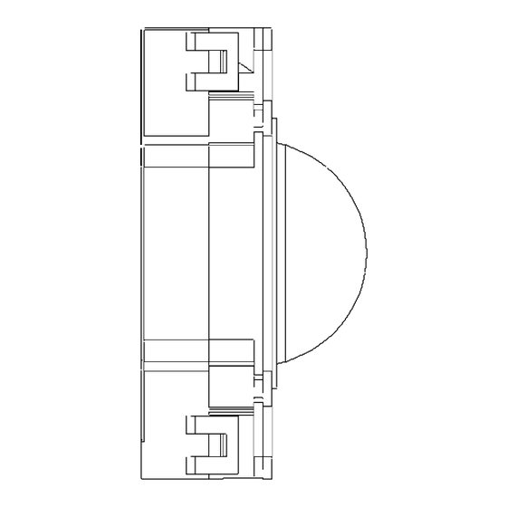
Geräteaufbau (Bild 1 und 2)
(NU) Nicht benutzt (ohne Audio)
(1) Kamera-Feststellschraube
(2) Kamera
(3) Infrarotbeleuchtung
(4) Anschlussklemmen
Klemme X/X:
2Draht-Busleitung
Klemme L/L:
Lichttaster Anschluss
Klemme T/T:
potenzialfreier Türöffner Schaltkontakt: nur
in der Betriebsart „Zugehörige Türkamera"
verwendet (7)
Klemme H/H:
Kameraheizung
(5) Status-LED – signalisiert aktiven Zustand
(6) Drehschalter Türadresse (rot)
Adressen dürfen im Strang nicht
doppelt vergeben werden.
(7) Betriebsartschalter
Programmierung des KameraBetriebsmodus
Dip-
Schalter
1
2
Zugeordnete
Türkamera (Audio-
OFF OFF
Türstation ist der
Kamera zugeordnet
(Bild 4)
Zusätzliche Tür-
kamera (Umschaltung
ON
OFF
über Funktions
oder
Zusätzliche Tür-
kamera (Umschaltung
OFF ON
nur über
Funktionstaste
(6)
Stand Alone Kamera
(Einschaltung nur
ON
ON
ON
über Funktionstaste
1 2
2)
1) Das Audiomodul der Aussenstation muss gleich
eingestellt sein die das Videomodul (Parameter
„1" oder Dipschalter 1 auf „ON", je nach verwendetem
Audiomodul)
2) Innenstation-Video
Montage und elektrischer Anschluss
• Elektrischer Schlag bei Berühren
spannungsführender Teile in der
Einbauumgebung!
• Elektrischer Schlag kann zum Tod führen!
• Vor Arbeiten an Gerät oder Last alle
zugehörigen Leitungsschutzschalter
freischalten. Spannungsführende Teile in
der Umgebung abdecken!
e
Einstellungen
des Adress-
Betriebsart
Drehschalters
Wie zugeordneter
Türlautsprecher
)
1)
Zugeordneter
Türlautsprecher
-
(+1)
-Taste
)
2)
Zugeordneter
Türlautsprecher
(+1)
vorher gehen hende
)
2)
Kamera (+1)
Freie Tür adresse
)
auf
Safety instructions
Electrical equipment may only be installed and
assembled by qualified electricians.
Failure to comply with these instructions may
result in damage to the device, fire or other
hazards.
When installing and laying cables, always com-
ply with the applicable regulations and stand-
ards for SELV electrical circuits.
These instructions are an integral component
of the product and must be retained by the end
user.
Design and layout of the device
(figures 1 and 2)
(NU) Not used (without audio)
(1) Camera setscrew
(2) Camera
(3) Infrared lighting
(4) Connecting terminals
Terminal X/X:
2-wire video bus cable
Terminal L/L:
light button connection
Terminal T/T:
potential-free door release switching contact:
used only in the "Associated door camera"
operating mode (7)
Terminal H/H:
camera heating
(5) Status LED – signalises active state
(6) Rotary switch door address (red)
Addresses must not be assigned twice in
the line.
(7) Operating mode switch
Camera operating mode setting:
DIP-switch
Operating mode
1
2
Associated door
camera (audio
OFF OFF
outdoor caller unit
allocated to the
camera (figure 4)
)
1)
Additional door
camera (change-over
ON
OFF
via function
or
buttons
)
2)
Additional door
camera (change-over
OFF ON
via function button
only
)
2)
Stand-alone camera
(switched on via
ON
ON
function button
only
)
2)
1) The outdoor caller unit audio module must be
configured in audio/video mode (parameter
1 or DIP switch 1 ON, depending on the outdoor caller
unit version)
2) Indoor unit
Installation and electrical connection
• Touching live parts in the installation
environment can result in an electric
shock!
• An electric shock can be lethal!
• Before working on the device or load,
disconnect all associated circuit breakers.
Cover all live parts in the area!
z
Address rotary
switch settings
Door
loudspeaker, as
assigned
Assigned door
loudspeaker (+1)
Assigned door
loudspeaker (+1)
Previous camera
(+1)
Free door
address
set at

Verwandte Anleitungen für ELCOM REU512Y


Inhaltszusammenfassung für ELCOM REU512Y
- Seite 1 Design and layout of the device (NU) Nicht benutzt (ohne Audio) (figures 1 and 2) (1) Kamera-Feststellschraube (NU) Not used (without audio) (2) Kamera REU512Y (1) Camera setscrew (3) Infrarotbeleuchtung (2) Camera (4) Anschlussklemmen Video-Modul Einbau 2Draht (3) Infrared lighting...
- Seite 2 0,8 mm Dimensions W x H x D 100 x 100 x 50 mm Abmessungen B x H x T 100 x 100 x 50 mm Elcom Kommunikation GmbH-Zum Gunterstal - 66440 BLIESKASTEL-GERMANY - www.hager.de Elcom 10.18 6LE004225A Ind. A...