Fujitsu FUTRO S450 Bedienungsanleitung
Flash-speicher und passives kühlkonzept
Inhaltsverzeichnis
Verfügbare Sprachen
Verfügbare Sprachen
Quicklinks
Kapitel
Inhaltsverzeichnis

Verwandte Anleitungen für Fujitsu FUTRO S450


Inhaltszusammenfassung für Fujitsu FUTRO S450
- Seite 1 FUTRO S450 Operating Manual...
- Seite 2 Sie haben..technische Fragen oder Probleme? Wenden Sie sich bitte an: • unsere Hotline/Help Desk (siehe die mitgelieferte Help Desk-Liste oder im Internet: "http://ts.fujitsu.com/helpdesk") • Ihren zuständigen Vertriebspartner • Ihre Verkaufsstelle Weitere Informationen finden Sie in den Handbüchern "Sicherheit" und "Garantie".
- Seite 4 Published by Fujitsu Technology Solutions GmbH A26361-K522-Z226-1-7419, Edition 2 2009/06 Produced by XEROX Global Services...
- Seite 5 FUTRO S450 Operating Manual Deutsch English...
- Seite 6 FUTRO sind eingetragene Warenzeichen der Fujitsu Technology Solutions GmbH. Microsoft, MS, MS-DOS, Windows, Windows NT, Windows 2000, Windows XP und Windows Vista sind eingetragene Warenzeichen der Microsoft Corporation. VESA und DPMS sind Warenzeichen der Video Electronics Standards Association. PS/2 ist ein eingetragenes Warenzeichen von International Business Machines, Inc.
-
Seite 7: Inhaltsverzeichnis
Ihr FUTRO S450......... - Seite 8 Inhalt Deutsch A26361-K522-Z226-1-7419, Ausgabe 2...
-
Seite 9: Ihr Futro S450
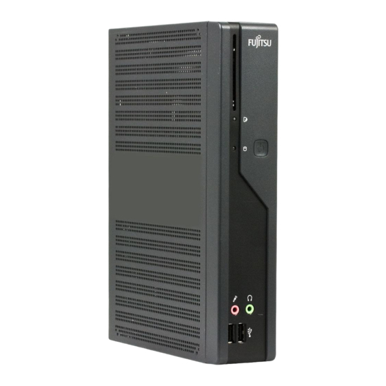
Ihr FUTRO S450... Ihr FUTRO S450... …ist ein universeller Netzwerk-Client. Das intelligente und flexible Terminal ist zuverlässig und leicht zu warten. Der Thin Client benötigt keine Lüfter und keine Festplatte. Dadurch ist er besonders leise im Betrieb. Das Betriebssystem ist auf einem Compact Flash installiert. -
Seite 10: Wichtige Hinweise
Wichtige Hinweise Wichtige Hinweise Wichtige Hinweise Hinweise In diesem Kapitel finden Sie unter anderem Sicherheitshinweise, die Sie beim Umgang mit Ihrem Gerät unbedingt beachten müssen. Sicherheitshinweise Sicherheitshinweise Hinweis Beachten Sie die Sicherheitshinweise im Handbuch "Sicherheit" und die nachfolgenden Sicherheitshinweise. Beachten Sie beim Aufstellen und beim Betrieb des Geräts die Hinweise für die Umgebungsbedingungen im Kapitel "Technische Daten ", Seite 24 und das Kapitel... -
Seite 11: Gerät Reinigen
Wichtige Hinweise Gerät reinigen Gerät Transport Wiedertransport Systemeinheit,sieheGerät Schalten Sie das Gerät und alle daran angeschlossenen Geräte aus und ziehen Sie den Netzstecker aus der geerdeten Schutzkontakt-Steckdose. Der Gehäuseinnenraum des Geräts darf nur von autorisiertem Fachpersonal gereinigt werden. Verwenden Sie für die Reinigung kein Scheuerpulver und keine Kunststoff lösenden Reinigungsmittel. -
Seite 12: Fcc Class B Compliance Statement
• Consult the dealer or an experienced radio/TV technician for help. Fujitsu Technology Solutions GmbH is not responsible for any radio or television interference caused by unauthorized modifications of this equipment or the substitution or attachment of connecting cables and equipment other than those specified by Fujitsu Technology Solutions GmbH. -
Seite 13: Inbetriebnahme
Inbetriebnahme Inbetriebnahme Inbetriebnahme Beachten Sie die Sicherheitshinweise im Kapitel "Wichtige Hinweise", Seite Anschlüsse und Bedienelemente Anschlüsse In diesem Kapitel werden die einzelnen Hardware-Komponenten Ihres Geräts vorgestellt. Sie erhalten eine Übersicht über die Anschlüsse und Bedienelemente des Geräts. Machen Sie sich mit diesen Elementen vertraut, bevor Sie mit dem Gerät arbeiten. Vorderansicht Einschalter Ausschalter... -
Seite 14: Rückansicht
Inbetriebnahme Rückansicht RJ45-LAN-Anschluss PS/2-Mausanschluss Einbauplatz PS/2-Tastaturanschluss Bildschirmanschluss SerielleSchnittstelle USB-Anschlüsse Audioausgang Gleichspannungsbuchse Audioeingang KensingtonLock 1 = Blende 7 = Gleichspannungsbuchse (DC IN) 2 = Serielle Schnittstelle 8 = Kensington Lock-Vorrichtung 3 = Audioausgang (Line Out) 9 = PS/2-Mausanschluss 4 = USB-Anschlüsse (Universal Serial Bus) 10 = RJ45-LAN-Anschluss (Local Area Network) 5 = DVI-Bildschirmanschluss... -
Seite 15: Gerät Aufstellen
Inbetriebnahme Gerät aufstellen Damit das Gehäuse ausreichend belüftet wird und um Überhitzung zu vermeiden, darf das Gerät nur mit befestigtem Standfuß betrieben werden. Montieren Sie die Standfüße für waagerechten oder senkrechten Betrieb (siehe "Senkrechte Betriebslage", Seite 7 "Waagerechte Betriebslage (optional)", Seite Standfüße für waagerechten Betrieb sind optional erhältlich. -
Seite 16: Waagerechte Betriebslage (Optional)
Inbetriebnahme Waagerechte Betriebslage (optional) Gehen Sie wie folgt vor, um das Gerät in waagrechter Betriebslage zu betreiben: WaagrechteBetriebslage Betriebslagewaagrecht Aufstellfüße ► Lösen Sie gegebenfalls die Leitungen. ► Legen Sie das Gerät auf einer stabilen, ebenen und sauberen Unterlage auf die Oberseite. ►... -
Seite 17: Bildschirm, Maus Und Tastatur Anschließen
Inbetriebnahme Bildschirm, Maus und Tastatur anschließen PS/2-Tastaturanschluss, USB-Anschluss, violett schwarz (USB-Maus, USB-Tastatur) DVI-Bildschirmanschluss, PS/2-Mausanschluss, weiß grün Bildschirm anschließen ► Bereiten Sie den Bildschirm vor, wie in der Betriebsanleitung zum Bildschirm beschrieben (z. B. Leitungen stecken). Bildschirm ► Stecken Sie die Datenleitung in den DVI-Bildschirmanschluss des Geräts. ►... -
Seite 18: Maus Anschließen
Inbetriebnahme Maus anschließen Maus Anschließen USB-Maus anschließen ► Schließen Sie die USB-Maus an einen USB-Anschluss des Geräts an. USB-Anschluss USB-Anschluss PS/2-Maus anschließen Wenn Sie am PS/2-Mausanschluss keine Maus anschließen, können Sie im BIOS-Setup den Maus-Controller abschalten und so den IRQ12 für eine andere Anwendung freigeben. ►... -
Seite 19: Externe Geräte Anschließen
Inbetriebnahme Externe Geräte anschließen Lesen Sie die Dokumentation zum externen Gerät, bevor Sie es anschließen. Außer bei USB-Geräten müssen die Netzstecker gezogen sein, wenn Sie externe Geräte anschließen! Bei Gewitter dürfen Sie Leitungen weder stecken noch lösen. Fassen Sie beim Lösen einer Leitung immer am Stecker an. Ziehen Sie nicht an der Leitung! Halten Sie beim Anschließen oder Lösen von Leitungen die nachfolgend beschriebene Reihenfolge ein. -
Seite 20: Anschlüsse Am Gerät
Inbetriebnahme Anschlüsse am Gerät Schnittstellen ExterneGeräte Gerät Die Anschlüsse finden Sie an Vorder- und Rückseite des Geräts. Welche Anschlüsse an Ihrem Gerät verfügbar sind, hängt davon ab, welche Ausbaustufe Sie gewählt haben. Die Standardanschlüsse sind durch die nachfolgenden oder durch ähnliche Symbole gekennzeichnet. Genauere Angaben zur Position der Anschlüsse finden Sie im Handbuch zum Mainboard. -
Seite 21: Externe Geräte An Die Serielle Schnittstelle Anschließen
Inbetriebnahme Externe Geräte an die serielle Schnittstelle anschließen SerielleSchnittstelle SerielleSchnittstelle ExterneGeräte Geräte An die serielle Schnittstelle können Sie externe Geräte anschließen (z. B. einen Drucker oder ein Modem). ► Schließen Sie die Datenleitung an das externe Gerät an. ► Schließen Sie die Datenleitung je nach Gerät an die serielle Schnittstelle an. Eine genaue Beschreibung, wie Sie das externe Gerät an die passende Schnittstelle anschließen, entnehmen Sie der Dokumentation zum externen Gerät. -
Seite 22: Mikrofon, Kopfhörer Und Line-Out-Geräte Anschließen
Inbetriebnahme Mikrofon, Kopfhörer und Line-Out-Geräte anschließen Mikrofon Kopfhörer Line-Out-Geräte ► Schließen Sie das Mikrofon an den Mikrofonanschluss an. ► Schließen Sie den Kopfhörer an den Kopfhöreranschluss an. ► Schließen Sie Line-Out-Geräte an den Audioausgang an. ► Schließen Sie Line-In-Geräte an den Audioeingang an. Netzadapter anschließen Netzadapter ►... -
Seite 23: Bedienung
Bedienung Bedienung Gerät einschalten ► Schalten Sie gegebenenfalls den Bildschirm ein (siehe Betriebsanleitung des Bildschirms). Gerät Bildschirm ► Schalten Sie das Gerät mit dem Hauptschalter an der Rückseite des Geräts ein (falls vorhanden). ► Drücken Sie den Ein-/Ausschalter an der Vorderseite des Geräts. Die Betriebsanzeige leuchtet grün, das Gerät startet. -
Seite 24: Bios-Setup Aufrufen
Bedienung BIOS-Setup aufrufen BIOS-Setup ► Wenn das System startet, drücken Sie (eventuell mehrmals) die Taste Das BIOS-Setup wird gestartet. Sie erreichen weitere Einstellmöglichkeiten im BIOS-Setup, wenn Sie eines der Register auswählen. PXE-Systemstart PXE-Systemstart ► Schalten Sie das Gerät mit dem Ein-/Ausschalter ein. ►... - Seite 25 Bedienung Folgende Einstellungen sind möglich: Angabe des verwendeten Systemstart- Protokolls. Network Boot PXE (Standard) Protocol: oder RPL Es wird immer zuerst das Netzwerk gestartet, Boot Order: Int 19h bevor die lokalen Geräte aktiviert werden. Wenn ein BBS-BIOS (BIOS Boot Specification) PnP/ BEV (BBS) vorhanden ist, wird das System durch das BBS-BIOS gestartet.
-
Seite 26: Systemerweiterungen
Systemerweiterungen Systemerweiterungen Erweiterungen Gerät Systemerweiterung Optional können Sie folgende Komponenten einbauen: • ein SmartCard-Leser-Modul Es kann sinnvoll sein, wenn Sie sich einige Teile dieses Kapitels ausdrucken, da das Gerät beim Ein-/Ausbau von Systemerweiterungen ausgeschaltet sein muss. Eventuell ist für eine Systemerweiterung oder Hardware-Hochrüstung ein Update des BIOS notwendig. -
Seite 27: Gehäuse Öffnen
Systemerweiterungen Gehäuse öffnen Gehäuse Gerät Beachten Sie, dass verschiedene Komponenten auf dem Mainboard sehr heiß sein können, wenn das Gerät vor kurzem noch aktiv war. Diese Komponenten können durch folgendes Symbol gekennzeichnet sein. ► Schalten Sie das Gerät aus. Das Gerät darf sich nicht im Energiesparmodus befinden! Beachten Sie die Sicherheitshinweise im Kapitel "Wichtige Hinweise", Seite Ziehen Sie den Netzstecker aus der Steckdose. -
Seite 28: Gehäuse Schließen
Systemerweiterungen Gehäuse schließen Gehäuse Gehäusedeckel ► Setzen Sie den Gehäusedeckel wieder auf das Gerät und schieben Sie ihn nach hinten. ► Befestigen Sie den Gehäusedeckel mit den beiden Schrauben an der Rückseite des Geräts. Achten Sie darauf, dass die Leitungen nicht zwischen Gehäuse und Bauteilen eingeklemmt werden! ►... -
Seite 29: Smartcard-Leser Einbauen
Systemerweiterungen SmartCard-Leser einbauen SmartCard-Leser Sie können, sofern nicht bereits vorhanden, einen SmartCard-Leser einbauen. ► Schließen Sie die Leitung am SmartCard-Leser an (1) und schließen Sie die Leitung am Stecker auf dem Mainboard an (2). ► Setzen Sie den SmartCard-Leser in Pfeilrichtung (3) mit der Bauteilseite nach unten auf die Befestigungsbolzen. -
Seite 30: Smartcard-Leser Ausbauen
Systemerweiterungen SmartCard-Leser ausbauen SmartCard-Leser ► Öffnen Sie das Gehäuse (siehe "Gehäuse öffnen", Seite 19). ► Ziehen Sie die Leitung vom SmartCard-Leser (1) und vom Mainboard (2). ► Lösen Sie die Schrauben (3). ► Heben Sie den SmartCard-Leser von den Befestigungsbolzen ab (4). ►... -
Seite 31: Lithium-Batterie Tauschen
Systemerweiterungen Lithium-Batterie tauschen Damit die Systeminformation dauerhaft gespeichert werden kann, ist eine Lithium-Batterie eingebaut, die den CMOS-Speicher mit Strom versorgt. Wenn die Spannung der Batterie zu niedrig oder die Batterie leer ist, wird eine entsprechende Fehlermeldung ausgegeben. Die Lithium-Batterie muss dann ausgetauscht werden. Bei unsachgemäßem Austausch der Lithium-Batterie besteht Explosionsgefahr! Die Lithium-Batterie darf nur durch identische oder vom Hersteller empfohlene Typen ersetzt werden. -
Seite 32: Technische Daten
Technische Daten Technische Daten TechnischeDaten Es dürfen nicht mehrere Geräte übereinander gestapelt werden. Thin Client Elektrische Daten Prozessor: AMD Sempron TF20 Nennspannung: 20 V Maximaler Nennstrom: 3,25 A Abmessungen Breite/Tiefe/Höhe (mit Standfuß): 266 mm/97 mm/191 mm Breite/Tiefe/Höhe (ohne Standfuß): 250 mm/52 mm/191 mm Gewicht im Grundausbau: ca.