Herunterladen Inhalt Inhalt Diese Seite drucken
Inhaltsverzeichnis

Werbung

Verfügbare Sprachen
  • DE

Verfügbare Sprachen

  • DEUTSCH, seite 1
Gebrauchsanleitung
Dekorative Abzugshaube
Instruction manual
Decorative extraction hood
Manuel d'instructions utilisateur
Hotte décorative
Manuale d'uso
Cappa aspirante decorativa
Gebruiksaanwijzing
Decoratieve dampafzuigkap
Руководство по эксплуатации
Декоративная вытяжка
D: Nachdruck, auch auszugsweise, nicht gestattet! GB: Reproduction, even in extracts, is not permitted! F: Toute reproduction de ce mode d'emploi
même par extraits est interdite ! IT: È vietata la riproduzione, anche parziale. NL: Nadruk, ook slechts gedeeltelijk, niet toegestaan!
Anleitung, Nr.: 11.002.1013
RUS: Перепечатка, даже частичная, не разрешается!
K-600/A Inox, K-900/A Inox

Werbung

Inhaltsverzeichnis
loading

Inhaltszusammenfassung für Cata K-600/A Inox

  • Seite 1 K-600/A Inox, K-900/A Inox Gebrauchsanleitung Dekorative Abzugshaube Instruction manual Decorative extraction hood Manuel d’instructions utilisateur Hotte décorative Manuale d’uso Cappa aspirante decorativa Gebruiksaanwijzing Decoratieve dampafzuigkap Руководство по эксплуатации Декоративная вытяжка D: Nachdruck, auch auszugsweise, nicht gestattet! GB: Reproduction, even in extracts, is not permitted! F: Toute reproduction de ce mode d’emploi même par extraits est interdite ! IT: È...
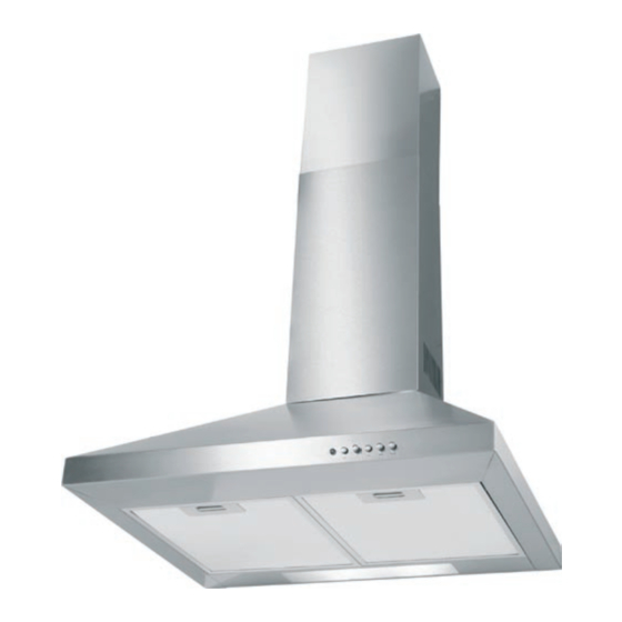
  • Seite 2: Lhre Abzugshaube Stellt Sich Vor

    Information lhre Abzugshaube stellt sich vor Wandmontage Ausstattungsmerkmale Wahlweise Abluft- oder Umluftbetrieb Betrieb mit zusätzlicher externer Absaugung möglich Drei Gebläsestufen Leuchte Oberflächen aus Edelstahl Auswaschbare Metall-Fettfilter (spülmaschinenfest) 1. Packen Sie das Gerät aus und entfernen Sie alle Verpackungsteile, Kontrolle ist besser Kunststoffprofile, Klebestreifen und Schaumpolster. 2. Prüfen Sie, ob alle im Lieferumfang beschriebenen Teile vorhanden sind: Einzelteile (siehe ,,Teileliste”, Seite 7) Gebrauchsanleitung 3.
  • Seite 3: Inhaltsverzeichnis

    Information Inhaltsverzeichnis lhre Abzugshaube stellt sich vor Bedienung Bedienung lnformation Gebläse Ausstattungsmerkmale Kontrolle ist besser Beleuchtung Zubehör Bestimmungsgemäßer Gebrauch Pflege und Wartung Allgemeines lnhaltsverzeichnis Reinigung 5 Minuten für lhre Sicherheit Fettfilter reinigen Begriffserklärung (Abluft- und Umluftbetrieb) Sicherheitshinweise Kohlefilter erneuern Besondere Sicherheitshinweise für (nur bei Umluftbetrieb) Abluftbetrieb Lampen wechseln Teileliste Problembehebung Informationen zur Montage Umweltschutzhinweis Umluftbetrieb Verpackungs-Tipps Abluftbetrieb...
  • Seite 4: Minuten Für Lhre Sicherheit

    Information 5 Minuten für Ihre Sicherheit ... 5 Minuten sollte Ihnen Ihre Sicherheit wert sein! Länger dauert es nicht, unsere Sicherheitshinweise durchzulesen. Folgende Signalbegriffe finden Sie in dieser Anleitung: Begriffserklärung Hohes Risiko. Missachtung der Warnung kann Schaden für Leib und Gefahr! Leben verursachen. Mittleres Risiko. Missachtung der Warnung kann einen Sachschaden Achtung! verursachen. Geringes Risiko. Sachverhalte, die im Umgang mit dem Gerät beachtet Wichtig! werden sollten.
  • Seite 5: Gefahren Für Kinder Und Personen Mit Eingeschränkten

    5 Minuten für Ihre Sicherheit... Information Beachten Sie bei der Montage, dass einige Teile scharfe Kanten Verletzungsgefahr! aufweisen. Verletzungsgefahr! Benutzen Sie zur Montage eine stabile Stehleiter. Gefahren für Kinder und Personen mit eingeschränkten Dieses Gerät ist nicht dafür bestimmt, durch Personen (einschließlich physischen, sensorischen oder geistigen Fähigkeiten! Kinder) mit eingeschränkten physischen, sensorischen oder geistigen Fähigkeiten oder mangels Erfahrung und / oder mangels Wissen benutzt zu werden, es sei denn, sie werden durch eine für ihre Sicherheit zuständige Person beaufsichtigt oder erhielten von ihr Anweisungen, wie das Gerät zu benutzen ist.
  • Seite 6: Besondere Sicherheitshinweise Für Abluftbetrieb

    5 Minuten für Ihre Sicherheit... Information Besondere Sicherheitshinweise für Abluftbetrieb Dem Raum, in dem eine Dunstabzugshaube im Abluftbetrieb arbeitet, Vergiftungs-/Brandgefahr! wird durch das Gebläse Luft entzogen und nach außen transportiert. Wenn in diesem Raum gleichzeitig raumluftabhängige Feuerstätten (z.B. Gas- oder andere Brennstoffheizungen) in Betrieb sind, kann diesen der für die Verbrennung notwendige Sauerstoff entzogen werden. Dies kann dazu führen, dass die Flamme erlischt und Gas austritt bzw.
  • Seite 7: Teileliste

    Information Teileliste Bevor Sie mit der Montage beginnen, prüfen Sie bitte, ob alle Einzelteile vorhanden und unbeschädigt sind. 1 Obere Kaminblende 2 Untere Kaminblende 3 Abzugshaube 4 Rohranschluss 5 Oberer Befestigungswinkel 6 Unterer Befestigungswinkel 7 Schrauben (4x) Abluftschlauch (ohne Abbildung, erforderlich für Abluftbetrieb) Nicht im Lieferumfang enthalten Kohlefilter (erforderlich für Umluftbetrieb) die Montage) 6 Befestigungsschrauben mit zugehörigen Dübeln (erforderlich für...
  • Seite 8: Informationen Zur Montage

    Information Information Informationen zur Montage Ihre Dunstabzugshaube kann im Umluft- oder Abluftbetrieb benutzt werden. Beim Umluftbetrieb werden die Küchendünste angesaugt und nach der Reinigung Umluftbetrieb durch die oberen Luftaustrittsöffnungen wieder der Raumluft zugeführt. Die Reinigung erfolgt durch den Fettfilter und zusätzlich durch den Kohlefilter (Geruchsfilter mit Aktivkohle; nicht im Lieferumfang enthalten). Einfache Montage Nachteil: Mit zunehmender Verschmutzung des Kohlefilters lassen Reinigungs- Vorteil: und Ansaugwirkung nach. Der Kohlefilter muss je nach Benutzung etwa alle drei Monate erneuert werden.
  • Seite 9: Stromanschluss

    Informationen zur Montage Information Information Damit später kein störendes Kabel sichtbar ist, sollten Sie auch den Stromanschluss Stromanschluss vor der Montage planen. Arbeiten an Elektroinstallationen dürfen nur von autorisiertem Gefahr! Fachpersonal durchgeführt werden. Benötigen Sie eine zusätzliche Steckdose für das Gerät, beauftragen Sie einen Elektrofachbetrieb. Es muss die gesetzliche Vorschrift eingehalten werden, dass der Stecker Erreichbarkeit des Stromanschlusses zugänglich ist. D.h. auch nach Montage der beiden Kaminblenden müssen Sie den Stecker erreichen können.
  • Seite 10: Vorbereitungen Zur Montage

    Vorbereitung Vorbereitungen zur Montage Zur Montage benötigen Sie folgendes Werkzeug und Zubehör: Werkzeuge und Hilfsmittel Kreuzschlitz-Schraubendreher, Größe 1 Bohrmaschine mit Steinbohrer Ø = 6 mm Maßband / Zollstock Wasserwaage Bleistift stabile Stehleiter Aktivkohlefilter für Umluftbetrieb Abluftschlauch für Abluftbetrieb Dübel (6x) Befestigungsschrauben(6x) empfehlen, Montage einer weiteren Person Wichtig! durchzuführen. Beachten Sie die Reihenfolge der Montageanleitung.
  • Seite 11: Montage

    Vorbereitung Montage Abzugshaube montieren Stellen Sie sicher, dass beim Bohren der Löcher keine Leitungen Achtung! beschädigt werden. Beachten Sie die Gebrauchsanleitung ihres Herds! Wird ein größerer Wichtig! Abstand als 65 cm vorgeschrieben, muss dieser berücksichtigt werden. 1. Um das Gerät exakt über der Mitte des Herds zu platzieren, zeichnen Sie eine Hilfslinie an die Wand (senkrechte Linie mit Hilfe einer Wasserwaage oder einem Lot von der Mitte des Herds bis zur Decke). Achten Sie darauf, nicht an Stellen der Wand anzuzeichnen, die nach der Montage noch sichtbar sind.
  • Seite 12: Luftschlauch Für Abluftbetrieb Montieren

    Montage Vorbereitung 1. Montieren Sie den Rohranschluss 4 mit den Schrauben 7 über die Luftschlauch für Abluftbetrieb montieren Kaminöffnung der Haube. 2. Schieben Sie den Abluftschlauch (nicht mitgeliefert) auf den Rohranschluss 4. Befestigen Sie den Schlauch mittels der Schelle des Schlauches am Rohranschluss. 3. Schieben Sie das obere Ende des Abluftschlauches so in den Wanddurchbruch, dass der Schlauch bis zur Wand-Außenkante reicht. Um den Geräuschpegel klein zu halten und die Arbeitsleistung Wichtig! der Haube optimal zu nutzen, empfehlen wir, einen passenden...
  • Seite 13: Kamin Montieren

    Montage Vorbereitung Kamin montieren Achten Sie darauf, dass zwischen Decke und oberer Kaminblende 1 Wichtig! ausreichend Platz für das Verlegen des Netzkabels bleibt. 1. Hängen Sie die untere Kaminblende 2 in die beiden Nuten des Befestigungswinkel 6 bis zum Anschlag ein. Setzen Sie diese anschließend auf die Abzugshaube 3. Zeichnen Sie die zwei Bohrlöcher an.
  • Seite 14 Montage Vorbereitung 5. Halten Sie den Befestigungswinkel 5 in der gewünschten Kaminhöhe über dem Befestigungswinkel 6 waagerecht so an die Wand, dass die Mitte des Winkels und die senkrechte Hilfslinie fluchten. Achten Sie hierbei auf die Höhe der oberen Kaminblende 1 und deren Abstand zur Decke. Zeichnen Sie die zwei Bohrlöcher an. 6. Bohren Sie an den markierten Stellen zwei Löcher mit einem Durchmesser von 6 mm.
  • Seite 15: Kohlefilter Für Umluftbetrieb Einsetzen

    Montage Vorbereitung Die Kohlefilter (Geruchsfilter) sind mit Aktivkohle gefüllt, die die Küchendünste Kohlefilter für Umluftbetrieb einsetzen während des Kochens reduzieren. Bei regelmäßigem Gebrauch sollten Sie diese Filter etwa alle zwei Monate wechseln (siehe ,,Pflege und Wartung” - Kohlefilter, Seite 18). 1. Schieben Sie die Verriegelung der beiden Fettfilter nach hinten und nehmen Sie diese vorsichtig nach unten ab. 2. Setzen Sie die beiden Kohlefilter auf beiden Seiten des Motorgehäuses ein und drehen Sie diese fest. 3. Setzen Sie die Fettfilter wieder in die hinteren Aussparungen ein.
  • Seite 16: Bedienung

    Bedienung Bedienung Das Gebläse Ihrer Abzugshaube ist in drei Stufen einstellbar. Auf Stufe Gebläse arbeitet das Gebläse am langsamsten, auf Stufe 13 am schnellsten. • Schalten Sie das Gebläse ein, wenn Sie mit dem Kochen oder Braten beginnen. So wird der Küchendunst von Anfang an beseitigt. Die Kontrollleuchte 9 leuchtet auf. • Lassen Sie das Gebläse laufen, solange Küchendünste oder Dampf entstehen. 1. Drücken Sie eine der Gebläsestufen 11, 12, Leistungsstufe zu wählen. 13, um die gewünschte 2. Drücken Sie 10, um das Gebläse auszuschalten.
  • Seite 17: Pflege Und Wartung

    Allgemeines Pflege und Wartung Reinigung Ziehen Sie vor dem Reinigen der Abzugshaube den Netzstecker. Sollte Gefahr! dieser schwer zugänglich sein, schalten Sie den Strom an dem neu installierten Schalter (siehe ,,Erreichbarkeit des Stromanschlusses”, Seite 9) ab. Fettrückstände an der Abzugshaube können sich bei großer Hitzeeinwirkung entzünden. Deshalb ist es wichtig, dass die Oberflächen der Abzugshaube regelmäßig gereinigt werden.
  • Seite 18: Kohlefilter Erneuern (Nur Bei Umluftbetrieb)

    Pflege und Wartung Allgemeines Die Kohlefilter dienen der Geruchsbeseitigung. Sie müssen erneuert werden, Kohlefilter erneuern (nur bei Umluftbetrieb) wenn die beim Kochen entstehenden Gerüche nicht mehr ausreichend gefiltert werden. Bei regelmäßigem Gebrauch sollten die Filter etwa alle zwei Monate erneuert werden. 1. Ziehen Sie den Netzstecker oder schalten Sie den Strom an dem neu installierten Schalter (siehe ,,Erreichbarkeit des Stromanschlusses”, Seite 9) 2. Schieben Sie die Verriegelung des Fettfilters nach hinten und nehmen Sie den Fettfilter vorsichtig nach unten ab.
  • Seite 19: Lampen Wechseln

    Pflege und Wartung Allgemeines Sollte eine der Lampen nicht mehr funktionieren, muss die Glühlampe Lampen wechseln ausgewechselt werden. Sie benötigen je eine Lampe mit Gewindesockel E14, 230 V, max. 40 Watt. Das Gerät arbeitet mit gefährlicher Spannung. Ziehen Sie vor Stromschlaggefahr! dem Wechseln der Lampe den Netzstecker. Berühren Sie keine stromführenden Teile im Inneren der Fassung. Lassen Sie die Lampe abkühlen, bevor Sie die Abdeckung abnehmen Verbrennungsgefahr! und die Lampe ausbauen.
  • Seite 20: Problembehebung

    Allgemeines Problembehebung Bei allen elektrischen Geräten können Störungen auftreten. Dabei muss es sich nicht um einen Defekt am Gerät handeln. Prüfen Sie deshalb bitte anhand der Tabelle, ob sich die Störung beseitigen lässt. Gebläse und Beleuchtung Das Gerät ist vom Netz Prüfen Sie den richtigen Sitz des Netzsteckers.
  • Seite 21: Umweltschutz Leicht Gemacht

    Allgemeines Umweltschutz leicht gemacht Unsere Verpackungen werden aus umweltfreundlichen, wiederverwertbaren Verpackungstipps Materialien hergestellt: – AußenverpackungausPappe – Formteile aus geschäumtem, FCKW-freiem Polystyrol (PS) – Folien und Beutel aus Polyäthylen (PE) – Spannbänder aus Polypropylen (PP). Sollten es Ihre räumlichen Verhältnisse zulassen, empfehlen wir Ihnen, die Verpackung zumindest während der Garantiezeit aufzubewahren. Sollte das Gerät zur Reparatur eingeschickt oder in eine der Reparatur-Annahmestellen gebracht werden müssen, ist das Gerät nur in der Originalverpackung ausreichend geschützt. Wenn Sie sich von der Verpackung trennen möchten, entsorgen Sie...
  • Seite 22: Stichwortverzeichnis

    Allgemeines Stichwortverzeichnis Abluftbetrieb Montage 8, 11 Vorbereitungen Abluftschlauch 8, 10, 12 Brandgefahr Problem beheben Bedienung Bestimmungsgemäßer Gebrauch Reinigung Betriebsleuchte Bezirksschornsteinfeger Service Sicherheitshinweise Entsorgung Sicherheitshinweise für Abluftbetrieb Gerät Stromanschluss Kohlefilter Stromschlaggefahr Erstickungsgefahr Technische Daten Fachberatung Teileliste Fehlersuchtabelle Fettfilter reinigen Umluftbetrieb Flambieren Umweltschutz Fritieren Wanddurchbruch 6, 8, 10 Gebläse Werkzeuge...
  • Seite 23: Technische Daten

    Allgemeines Technische Daten Model /Artikelnummer Dekorative Abzugshaube Dekorative Abzugshaube K-600/A Inox K-900/A Inox Netzanschluss: 230 - 240 V~ 50 Hz Leistung einer Lampe: max. 40 W Nennleistung: max. 220 W Anschluss Abluftschlauch: Ø 120 mm max. Luftdurchsatz bei Abluft: 620 m³/h Schutzklasse: Maße (B x T):...
  • Seite 24: Equipment Features

    Information Presenting your extraction hood Wall installation Equipment features Selection of extraction or circulating air mode Operation with additional external extraction system also possible Three fan stages Lamp Stainless steel surfaces Rinsable metal grease filter (dishwasher-safe) 1. Unpack the appliance and remove all parts, plastic sections, adhesive tape and Checking is better foam padding.
  • Seite 25 Information Table of contents Presenting your extraction hood Operating Operation Information Equipment features Checking is better Lighting Accessories Intended use Care and maintenance General Table of contents Cleaning 5 minutes for your safety Cleaning the grease filter (extraction and Explanation of terms circulating air mode) Safety information Replacing the carbon filters (only for Special safety information for circulating air mode) extraction mode Replacing lamps Parts list Troubleshooting Information for installation Environmental protection information Circulating air mode Packaging tips Extraction mode Disposal of the appliance Power connection...
  • Seite 26: Information

    Information 5 minutes for your safety ... Your safety should be worth 5 minutes to you! It doesn't take any longer to read through our safety information. The following symbols are used in our instructions: Explanation of terms High risk. Non-observance of the warning can result in injury to limb Danger! and danger to life. Medium risk. Non-observance of the warning can result in tangible Caution! damage. Low risk. Observe actual circumstances when operating the Important! appliance.
  • Seite 27 5 minutes for your safety Information During installation, pay attention to components that have sharp Risk of injury! edges. Risk of injury! Use a stable stepladder for installation. Hazards for children and persons with restricted physical, This appliance is not intended to be used by persons (including sensory or mental faculties! children) with restricted physical, sensory or mental faculties or lack of experience and / or knowledge, unless they are supervised...
  • Seite 28: Special Safety Information For Extraction Mode

    5 minutes for your safety Information Special safety information for extraction mode The fan extracts air from the room in which the extraction hood is Risk of toxication/fire! operated and transports it outside. If fireplaces depending on the room air are simultaneously in use in this room (e.g. gas or other fuel- powered heating systems), this can be withdrawn for the combustion of the necessary oxygen. This can result in the flame going out and gas escaping or the exhaust gas being sucked into the room.
  • Seite 29: Parts List

    Information Parts list Before starting installation, please check to make sure that all individual components are present and undamaged. 1 Upper chimney section 2 Lower chimney section 3 Extraction hood 4 Hose connection 5 Upper mounting bracket 6 Lower mounting bracket 7 Screws (4x) Not included in the scope of delivery Exhaust air hose (not shown, required for extraction mode) Carbon filters (required for circulating air mode) 6 fixing screws with wall plugs (required for installation)
  • Seite 30: Information For Installation

    Information Information for Installation Your extraction hood can be used in circulating air or extraction mode. In circulating air mode, the kitchen vapours are sucked in and, after purification, Circulating air mode discharged to the room air through the upper air discharge apertures. Purification is carried out by the grease filter and also by the carbon filter (odour filter with activated carbon; not in the scope of delivery). Simple installation Disadvantage: With increasing contamination of the carbon filter, the Advantage: purification and extraction effects recede. Depending on the use, the carbon filter must be replaced approximately every three months.
  • Seite 31: Power Connection

    Information for installation Information To avoid disturbing, visible cables later, the power connection should also be Power connection planned before installation. Work on the electrical installations must only be carried out by Danger! qualified personnel. If an additional socket is required for the appliance, commission a specialist electrical firm.
  • Seite 32: Preparations For Installation

    Preparation Preparations for installation You will need the following tools and equipment for the installation: Tools and equipment Phillips screwdriver, size 1 Masonry drill Ø = 6 mm Measuring tape/foot rule Spirit level Pencil Stable stepladder Activated carbon filter for circulating air mode Exhaust air hose for extraction mode Wall plugs (6x) Fixing screws (6x) We recommend asking a second person to assist you with the Important! installation.
  • Seite 33: Installation

    Preparation Installation Installing the extraction hood Make sure that when drilling the holes no lines are damaged. Plumb-line Caution! Please observe your cooker’s instruction manual! If a greater Important! clearance than 65 cm is specified, this must be taken into consideration.
  • Seite 34: Installing The Hose For Extraction Mode

    Installation Preparation 1. Install the hose connection 4 using the screws 7 above the hood’s chimney Installing the air hose for extraction mode opening. 2. Connect the exhaust air hose (not supplied) onto the hose connection 4. Affix the hose onto the hose connection using the hose’s clamp. 3. Insert the upper end of the exhaust air hose through the wall breakthrough in such a way that the hose reaches the outside edge of the wall.
  • Seite 35: Installing The Chimney

    Installation Preparation Installing the chimney Ensure that there is sufficient space to lay the mains cable between Important! the ceiling and the upper chimney section 1. 1. Hang the lower chimney section 2 into the two grooves on the mounting bracket 6 until it clicks into place. Then place it on the extraction hood 3. Mark the two holes.
  • Seite 36 Installation Preparation 5. Hold the mounting bracket 5 horizontally on the wall at the required chimney height about the mounting bracket 6 so that the centre of the bracket is flush with the vertical guide line. Pay attention to the height of the upper chimney section 1 and its clearance height to the ceiling. Mark the two holes. 6. Drill two holes with a diameter of 6 mm on the marked points. 7. Push the wall plugs (not supplied) into the holes.
  • Seite 37: Inserting The Carbon Filters For Circulating Air Mode

    Installation Preparation The carbon filters (odour filters) are filled with activated carbon that reduces the Inserting the carbon filters for circulating air mode kitchen vapours during cooking. If used regularly, these filters should be replaced approximately every two months (see “Care and maintenance” – Carbon filters, page 18). 1. Push the lock on both grease filters backwards and remove them carefully downwards. 2. Insert the two carbon filters on both sides of the motor housing and screw them in tightly. 3. Reinsert the grease filters in the rear recesses. 4. Push the lock downwards, press the front of the grease filters and release the lock. The grease filters click into place. Motor housing Grease �ilters Carbon �ilters English...
  • Seite 38: Operation

    Operation Operation The fan in your extraction hood can be set to three stages. The fan operates slowest in stage 11 and fastest in stage • Switch on the fan when starting to cook or roast. Thus, the kitchen vapours will be discharged from the start. The indicator light 9 illuminates. • Operate the fan so long as there are kitchen vapours or steam. 1.
  • Seite 39: Care And Maintenance

    General Care and maintenance Care and maintenance Before cleaning the extraction hood, disconnect the mains plug. If the Danger! plug is not easily accessible, disconnect the power supply using the recently installed switch (see “Accessibility of power supply”, page 9). Grease deposits on the extraction hood can ignite in cases of extreme heat.
  • Seite 40: Replacing The Carbon Filters (Only For Circulating Air Mode)

    Care and maintenance General The carbon filters remove the odours. They must be replaced when the odours Replacing the carbon filters (only for circulating air mode) generated by cooking can no longer be sufficiently filtered. If used regularly, the filters should be replaced approximately every two months. 1. Pull the plug out or disconnect the power supply using the recently installed switch (see “Accessibility of power supply”, page 9). 2. Push the lock on the grease filter backwards and remove the grease filter carefully downwards. 3. Remove the carbon filters on both sides of the motor housing. 4. Insert the two carbon filters on both sides of the motor housing and screw them in tightly. 5. Reinsert the grease filter in the rear recesses. 6. Push the lock downwards and press the grease filter into the holder. Release the lock and the grease filter clicks into place.
  • Seite 41: Replacing Lamps

    Care and maintenance General If one of the lamps no longer functions, the bulb must be replaced. You require a Replacing lamps bulb with an E 14 screw base, 230 V, max. 40 Watt. The appliance operates using a hazardous voltage. Before replacing Electrical shock hazard! the bulb, disconnect the mains plug. Do not touch any live components inside the socket. Before opening the cover and removing the bulb, allow the bulb to Risk of burns! cool down.
  • Seite 42: If There Is A Problem

    General If there is a problem Malfunctions can occur on all electrical appliances. Thereby, it is not necessarily a defect on the appliance. Therefore, using the table, check to see whether the malfunction can be rectified. Fan and lighting do not The appliance is not Check the connection of the mains plug. Use Problem Possible causes Solutions, tips function. connected to the mains. another electrical appliance and check the socket. Check the house fuse.
  • Seite 43: Environmental Protection Made Easy

    General Environmental protection made easy Our packaging is manufactured from environmentally friendly, recyclable Tips for packaging materials: – External packaging from carton – Moulded parts from foamed, CFC-free polystyrene (PS) – Film and bags from polythene (PE) – Fixing straps from polypropylen (PP). If the available space permits, we recommend that you retain the packaging at least until the end of the warranty period. If the appliance must be sent for repair or taken to one of the repair facilities, the appliance is sufficiently protected in the original packaging.
  • Seite 44 General Subject Index Accessories Local official heating inspector Carbon filter 8, 15, 18 Operating Checking Operating light Circulating air mode Cleaning Parts list Cleaning grease filter Power connection Core drilling 6, 8, 10 Rectify problem Danger of suffocation Replacing lamps Deep-fat frying Risk of fire Disposal Appliance Safety information Carbon filter Safety information for extraction mode Scope of delivery Electrical shock hazard Service Environmental protection Specialist advice Exhaust air hose 8, 10, 12 Extraction mode Technical data Tools...
  • Seite 45: Technical Data

    General Technical Data Model / article no. Decorative extraction hood Decorative extraction hood K-600/A Inox K-900/A Inox Mains connection: 230 - 240 V~ 50 Hz Lamp output: Max. 40 W Power rating: Max. 220 W Exhaust-air hose connection: Ø 120 mm Max. airflow with exhaust air: 620 m³/h...
  • Seite 46: Caractéristiques Techniques

    Information Présentation de votre appareil (hotte aspirante) Montage mural Caractéristiques techniques Utilisation au choix en mode recyclage ou en mode évacuation Utilisation avec aspiration externe supplémentaire possible Trois vitesses de ventilation Eclairage Parois extérieures en acier inoxydable Filtres anti-graisse en métal lavable (adapté au lavage en lave-vaisselle) Avant de procéder à l’installation de la hotte et avant toute utilisation veuillez lire attentivement la présente notice d’utilisation ainsi que les consignes de sécurité. Vous assurez ainsi un fonctionnement correct de l’appareil.
  • Seite 47 Information Sommaire Présentation de votre appareil (hotte Utilisation Utilisation Information aspirante) Ventilateur Caractéristiques de l’équipement Eclairage Précautions d’emploi Accessoires Entretien et maintenance Utilisation conforme de l‘appareil Divers Nettoyage Sommaire Nettoyage du filtre anti-graisse (mode 5 minutes pour votre sécurité évacuation et mode recyclage) Explication de termes techniques Remplacement du filtre à charbon Consignes de sécurité (en mode recyclage uniquement) Consignes de sécurité spécifiques Remplacement des lampes à l’utilisation en mode évacuation Résolution des problèmes Liste des pièces Indications pour la protection de Instructions de montage l‘environnement...
  • Seite 48: Information

    Information 5 minutes pour votre sécurité… 5 minutes, cela en vaut bien la peine pour votre sécurité ! Cela ne prend pas plus longtemps de lire nos consignes de sécurité. Vous trouverez dans ce mode d’emploi les signaux d’avertissement suivants: Définition des symboles Risque élevé. Un non-respect de l’avertissement mentionné peut Danger ! provoquer des dommages corporels et vitaux sur les personnes. Risque moyen. Le non-respect de l’avertissement mentionné peut Attention ! entraîner des dégâts matériels.
  • Seite 49 5 minutes pour votre sécurite Information Lors du montage, prenez garde car certaines pièces ont des arêtes Risque de blessure ! tranchantes. Risque de blessure ! Utilisez pour le montage un escabeau stable. Danger pour les enfants et les personnes ayant des capacités Cet appareil n’est pas destiné à être utilisé par des personnes (y physiques, sensorielles ou intellectuelles limitées ! compris des enfants) ayant des capacités physiques, sensorielles ou...
  • Seite 50 5 minutes pour votre sécurite Information Consignes de sécurité particulières pour l’utilisation en mode évacuation Dans une pièce où la hotte aspirante fonctionne en mode évacuation, Risque d’intoxication / d’incendie ! de l’air est aspiré par le ventilateur et évacué vers l’extérieur. Si dans la pièce d’autres foyers à air ambiant (par exemple chauffage au gaz ou autre combustible) f fonctionnent simultanément, alors ils sont privés de l’oxygène nécessaire à la combustion. Cela peut conduire à...
  • Seite 51: Liste Des Pièces

    Information Liste des pièces Avant de commencer l’installation, vérifiez qu’il ne manque aucune pièce et qu’elles ne soient pas endommagées. 1 Partie supérieure de la cheminée 2 Partie inférieure de la cheminée 3 Hotte 4 Tuyau de raccordement 5 Equerre de fixation supérieure 6 Equerre de fixation inférieure 7 Vis (4x) Non fourni en mode évacuation) Tuyau d‘évacuation (sans illustration. Nécessaire pour une utilisation Filtre à charbon (nécessaire pour une utilisation en mode recyclage) pour le montage) 6 vis de fixation avec les chevilles correspondantes (nécessaires N’utilisez pour l’installation que du matériel adapté...
  • Seite 52: Mode Recyclage

    Information Informations sur le montage Votre hotte aspirante peut être utilisée en mode recyclage ou en mode évacuation. Lors de l’utilisation en mode recyclage, les vapeurs de cuisson sont aspirées, et Utilisation en mode recyclage après épuration, sont réacheminées dans l’air ambiant par des orifices de sortie d’air. L’épuration est effectuée par le filtre anti-graisse et en plus par le filtre à charbon (filtre anti-odeur contenant du charbon actif, non inclus dans le matériel livré).
  • Seite 53: Branchement Électrique

    Informations sur le montage Information Afin qu’aucun câble gênant ne soit visible par la suite, prévoyez d’effectuer le Branchement électrique branchement électrique avant l’installation. Les travaux effectués sur des installations électriques ne doivent Danger! être réalisés que par des techniciens professionnels habilités. Si vous avez besoin d’une prise supplémentaire pour l’appareil, chargez un professionnel de l’électricité...
  • Seite 54: Préparatifs De Montage

    Préparatifs d‘installation Préparatifs de montage Pour l’installation vous aurez besoin des outils et des accessoires suivants: Outils et matériel recommandé Un tournevis cruciforme, taille 1 Une perceuse avec foret à béton de 6 mm de diamètre Un mètre à ruban/un mètre pliant Un niveau à bulle Un crayon à papier Un escabeau stable Un filtre à charbon actif pour l’utilisation en mode recyclage Un tuyau d’évacuation d’air pour l’utilisation en mode évacuation Chevilles (6x) Vis de fixation (6x) Nous vous recommandons de réaliser l’installation avec l’aide d’une Important autre personne.
  • Seite 55 Préparatifs d‘installation Installation Installer la hotte aspirante Assurez-vous de ne pas endommager de câbles en perçant les trous. Perpendiculaire Attention! Respectez le mode d’emploi de votre table de cuisson! S’il est Important! recommandé de prévoir un écart plus important que 65 cm, il faut se conformer à...
  • Seite 56 Préparatifs d‘installation Installation 1. Installez le raccordement pour le tuyau 4 à l’aide des vis 7 au-dessus de Installer le tuyau pour l’évacuation de l‘air l’ouverture de la cheminée de la hotte. 2. Insérez le tuyau d’évacuation de l’air (non fourni) au raccord de tube 4. Attachez le tuyau au raccord de tube au moyen du collier de serrage du tuyau. 3. Engagez l’extrémité supérieure du tuyau d’évacuation de l’air dans le trou percé dans le mur de telle façon que le tuyau arrive jusqu’au bord extérieur du mur. Pour maintenir un niveau sonore bas et faire une utilisation optimale Important! des capacités de la hotte nous vous recommandons d’utiliser un tuyau d’évacuation d’air adapté.
  • Seite 57 Installation Préparatifs d‘installation Installer la cheminée Veuillez à ce qu’il reste suffisamment d’espace entre le plafond Important! et la partie supérieure de la cheminée 1 pour poser le câble d’alimentation. 1. Insérez la partie inférieure de la cheminée 2 dans les deux rainures de l’équerre de fixation 6 jusqu’en butée. Puis posez-la sur la hotte aspirante 3. Marquez d’un trait de crayon les deux trous à percer.
  • Seite 58 Préparatifs d‘installation Installation 5. Maintenez l’équerre de fixation 5 à la hauteur à laquelle vous souhaitez fixer la cheminée au-dessus de l’équerre de fixation 6 horizontalement contre le mur de façon à ce que le centre de l’équerre et la ligne verticale tracée sur le mur soient alignées. Ce faisant, prenez bien en compte la hauteur de la partie supérieure de la cheminée 1 et son écart d‘avec le plafond. Marquez les deux trous à percer. 6. Percez aux endroits marqués deux trous d’un diamètre de 6 mm. 7. Enfoncez les chevilles (non fournies) dans les trous. 8. Posez l’équerre de fixation 1 au mur avec deux vis de fixation (non fournies).
  • Seite 59 Installation Préparatifs d‘installation Les filtres à charbon (filtres anti-odeur) sont remplis de charbon actif et réduisent Mise en place du filtre à charbon pour le mode recyclage les odeurs qui se dégagent pendant la cuisson. Dans le cas d’une utilisation régulière ces filtres doivent être changés environ tous les deux mois (voir la rubrique „ entretien et maintenance“ –filtre à charbon, page 18).
  • Seite 60: Utilisation

    Utilisation Utilisation Le ventilateur de votre hotte aspirante peut être réglé sur trois positions. En Ventilateur position 11 le ventilateur fonctionne au régime le plus lent, en position 13 sur le plus rapide. • Mettez le ventilateur en marche quand vous commencez la cuisson. Ainsi les odeurs de cuisine seront éliminées dès le départ. Le témoin de contrôle 9 s’allume. • Laissez fonctionner le ventilateur aussi longtemps qu’il se dégage des odeurs de cuisine ou de la vapeur. 1. Appuyez sur l’une des boutons de commande du ventilateur 11, 12, pour choisir la puissance désirée.
  • Seite 61: Entretien Et Maintenance

    Divers Entretien et maintenance Nettoyage Débranchez le cordon d’alimentation avant de nettoyer la hotte Danger! aspirante. Si ce dernier n’est que difficilement accessible, coupez le courant à l’interupteur nouvellement installé. (Consulter la rubrique „accessibilité du branchement électrique“, page 9). Les dépôts de graisse sur la hotte peuvent s’enflammer sous l’effet d’une forte chaleur. C’est pourquoi il est important de nettoyer régulièrement les parois de la hotte.
  • Seite 62 Divers Entretien et maintenance Les filtres à charbon servent à faire disparaitre les odeurs. Ils doivent être Remplacer le filtre à charbon (uniquement pour le mode recyclage) remplacés lorsque les odeurs qui se dégagent à la cuisson ne sont plus suffisamment filtrées. Dans le cas d’une utilisation régulière les filtres doivent être renouvelés environ tous les deux mois.
  • Seite 63: Remplacement Des Lampes

    Divers Entretien et maintenance Si l’une des lampes ne fonctionne plus, il faut alors remplacer l’ampoule. Il vous Remplacement des lampes faut une lampe à vis E14, 230 V, max. 40 Watt. L’appareil est alimenté sous une tension dangereuse. Débranchez le Risque de décharge électrique! cordon d’alimentation avant de remplacer la lampe. Ne touchez pas les parties conductrices de courant à...
  • Seite 64: En Cas De Problème

    Divers En cas de problème Avec tous les appareils électriques, un défaut peut se produire. Souvent, il ne s’agit pas d’un défaut sur l’appareil. Vérifier donc à l’aide de ce tableau si vous pouvez remédier au défaut constaté. Le ventilateur et l’éclairage L’appareil n’est pas alimenté Vérifiez la bonne assise de la fiche secteur. Problème Causes possibles Solutions, conseils ne fonctionnent pas. électriquement.
  • Seite 65: Protection De L'environnement Facilitée

    Divers Protection de l’environnement facilitée emballages sont fabriqués avec matériaux respectueux Conseils sur l’emballage l’environnement, recyclables : emballage extérieur en carton des pièces moulées en polystyrène expansé (PS), sans CFC, des films et des sachets en polyéthylène (PE), des bandes de serrage en polypropylène (PP). Si vous disposez de place suffisante, nous vous recommandons de conserver l’emballage au moins pendant la durée de garantie. Si l’appareil doit être envoyé pour réparation ou doit être apporté dans un des dépôts pour la réparation, l’appareil sera suffisamment protégé uniquement dans son emballage d’origine.
  • Seite 66: Index Des Mots-Clefs

    Divers Index des mots-clefs Accessoires Outils Appareil Percement du mur 6, 8, 10 Branchement électrique Pièces (liste des) Problèmes (résolution des) Produits fournis Carottage 6, 8, 10 Protection de l‘environnement Conseil professionnel Consignes de sécurité Consignes de sécurité pour le mode évacuation Risque de décharge électrique Contrôle Risque d‘étouffement Risque d‘incendie Données techniques Services Service de ramonage Elimination des éléments usagés Erreur (tableau de recherche d’) Témoin de marche Tuyau d’évacuation de l‘air 8, 10, 12...
  • Seite 67: Données Techniques

    Divers Données techniques Modèle /numéro de produit Hotte aspirante décorative Hotte aspirante décorative K-600/A Inox K-900/A Inox Alimentation: 230 - 240 V~ 50 Hz Puissance lampe: max. 40 W Puissance nominale: max. 220 W Raccordement tuyau d’évacuation de Ø 120 mm l‘air: Débit maximal en évacuation: 620 m³/h...
  • Seite 68: La Cappa Aspirante Si Presenta

    Informazione La cappa aspirante si presenta – Montaggio a parete Caratteristiche – funzionamento aspirante o filtrante regolabile – possibilità dell’esercizio con aspirazione esterna – uscita d’aria regolabile in alto o in fondo – illuminazione – superfici in acciaio inox – filtri antigrasso in metallo lavabile (anche in lavastoviglie) 1. Disimballare l’apparecchio e rimuovere tutte le parti dell’imballaggio, i profili Meglio controllare di plastica, il nastro adesivo e la gomma piuma. 2.
  • Seite 69 Appunto Indice La cappa aspirante si presenta Elementi di comando Comando Informazione Soffiatrice Caratteristiche Meglio controllare Illuminazione Accessori Uso conforme Cura e manutenzione Indicazioni generali Indice Pulizia 5 minuti per la vostra sicurezza Pulizia del filtro antigrasso Definizione dei termini (funzionamento aspirante e filtrante) Avvisi di sicurezza Sostituzione del filtro di carbonio Avvisi di sicurezza particolari per il (solo per il funzionamento aspirante) funzionamento aspirante Sostituire le lampadine...
  • Seite 70: Informazione

    Informazione 5 minuti per la vostra sicurezza ... La vostra sicurezza vale 5 minuti del vostro tempo! I nostri avvisi di sicurezza non richiedono più di questo tempo. Il presente manuale contiene i seguenti termini di segnale: Definizione dei termini Alto rischio. La non osservanza dell’avviso può provocare danni per la Pericolo! salute e per la vita.
  • Seite 71 5 minuti per la vostra sicurezza Informazione Prestare attenzione agli angoli taglienti di alcune componenti durante Pericolo di lesioni! il montaggio. Pericolo di lesioni! Per il montaggio si raccomanda l’utilizzo di una scala a libro stabile. Pericolo per bambini e persone con limitate capacità fisiche, L’apparecchio non è destinato all’utilizzo da parte di persone sensoriali o mentali! (compresi i bambini) con limitate capacità fisiche, sensoriali o mentali...
  • Seite 72: Avvisi Di Sicurezza Particolari Per Il Funzionamento Aspirante

    5 minuti per la vostra sicurezza Informazione Avvisi di sicurezza particolari per il funzionamento aspirante La soffiatrice aspira l’aria dall’ambiente in cui si adopera la cappa Pericolo di intossicazione/incendio! aspirante funzionamento aspirante, convogliandola verso l’esterno. Qualora nello stesso ambiente si adoperino dei focolari a camera aperta (ad es. stufe a gas o altri combustibili), la cappa aspirante potrebbe sottrarre a questi ultimi l’ossigeno necessario per la combustione. Di conseguenza si potrebbe spegnere la fiamma...
  • Seite 73: Lista Dei Pezzi

    Informazione Lista dei pezzi Accertarsi che tutti i pezzi singoli siano presenti e intatti prima di iniziare il montaggio. 1 tubo decorativo superiore 2 tubo decorativo inferiore 3 cappa aspirante 4 raccordo per tubi 5 squadretta di supporto superiore 6 squadretta di supporto inferiore 7 viti (4x) − tubo di scarico (senza immagine, indispensabile per il funzionamento Non compresi nella fornitura...
  • Seite 74: Informazioni Per Il Montaggio

    Informazione Informazioni per il montaggio É possibile adoperare la cappa aspirante in funzionamento aspirante o filtrante. In funzionamento filtrante la cappa aspira i vapori da cucina immettendoli, in Funzionamento filtrante seguito alla loro pulizia, di nuovo nell’ambiente tramite le aperture superiori. La pulizia avviene tramite il filtro antigrasso e inoltre tramite il filtro di carbonio (filtro antiodore con carbonio attivo; non compreso nella fornitura).
  • Seite 75: Accessibilità Dell'allacciamento Alla Rete Elettrica

    Informazioni per il montaggio Informazione Per evitare di avere i cavi a vista si consiglia di progettare l’allacciamento alla rete Allacciamento alla rete elettrica elettrica prima del montaggio. I lavori sulle installazioni elettriche sono riservati al solo personale Pericolo! autorizzato. Se per l’utilizzo dell’apparecchio fosse necessaria un’ulteriore presa elettrica...
  • Seite 76: Preparazioni Per Il Montaggio

    Preparazione Preparazioni per il montaggio Per il montaggio serve la seguente attrezzatura: Attrezzi e strumenti – cacciavite a croce, n° 1 – trapano con punta per pietra ø 6 mm – metro a nastro/metro pieghevole – bolla – matita – scala a libro stabile – filtro di carbonio attivo per funzionamento filtrante –...
  • Seite 77: Montaggio

    Preparazione Montaggio Montaggio della cappa aspirante Assicurarsi che durante la foratura non si rechino danni alle pendolo Attenzione! condutture. Si raccomanda di attenersi alle indicazioni del manuale d’uso della Importante! cucina a gas! Ove previsto dal manuale, si dovrà rispettare una distanza superiore a 65 cm.
  • Seite 78: Montaggio Del Tubo Di Scarico Per Il Funzionamento Aspirante

    Montaggio Preparazione 1. Montare il raccordo per tubi 4 con le viti 7 sopra l’apertura del camino della Montaggio del tubo di scarico per il funzionamento aspirante cappa. 2. Spingere il tubo di scarico (non compreso nella fornitura) sul raccordo 4, fissandolo con la fascetta del tubo sul raccordo. 3. Inserire l'estremità superiore del tubo di scarico nell’apertura della parete in modo che il tubo raggiunga il bordo esterno della parete. Per tenere il livello di rumorosità...
  • Seite 79: Montaggio Del Camino

    Montaggio Preparazione Montaggio del camino Si raccomanda di lasciare uno spazio sufficiente tra il soffitto e il tubo Importante! decorativo superiore 1 per la posa del cavo elettrico. 1. Inserire il tubo decorativo inferiore 2 fino all’arresto nelle due scanalature della squadretta di fissaggio 6 e posizionarla sulla cappa aspirante 3. Segnare i due punti per i fori. 2. Nei punti segnati, trapanare due fori con un diametro di 6 mm. 3. Inserire i tasselli (non compresi nella fornitura) nei fori.
  • Seite 80 Montaggio Preparazione 5. Posizionare la squadretta di fissaggio 5 orizzontalmente, sull’altezza desiderata del camino, sopra la squadretta di fissaggio 6 in modo che il centro della squadretta e la linea ausiliare verticale combacino, prestando attenzione all’altezza del tubo decorativo superiore 1 e la sua distanza dal soffitto. Segnare i due punti per i fori. 6. Nei punti segnati, trapanare due fori con un diametro di 6 mm. 7. Inserire i tasselli (non compresi nella fornitura) nei fori.
  • Seite 81 Montaggio Preparazione I filtri di carbonio (filtri antiodore) contengono carbonio attivo per ridurre Inserire il filtro di carbonio per il funzionamento filtrante i vapori da cucina durante la cottura. Con l’esercizio regolare si consiglia di sostituire i filtri ogni due mesi ca. (ved "Cura e manutenzione"- filtro di carbonio, pagina 18). 1. Spingere indietro il bloccaggio dei due filtri antigrasso e estrarre i filtri cautamente verso il basso. 2. Inserire e avvitare i due filtri di carbonio su entrambi i lati del basamento del motore.
  • Seite 82: Comando

    Comando Comando La soffiatrice della cappa aspirante è regolabile a 3 livelli. A livello 11 la Soffiatrice soffiatrice lavora più lentamente, a livello • Accendere la soffiatrice a inizio cottura o frittura. In tal modo il vapore da 13 più velocemente. cucina viene subito eliminato. Si accenderà la spia luminosa 9. • Per l’intera durata della formazione dei vapori da cucina tenere la soffiatrice accesa. 1. Per selezionare il livello di ventilazione desiderato, premere 11, 12, 2. Per spegnere la soffiatrice, premere 10.
  • Seite 83: Cura E Manutenzione

    Indicazioni generali Cura e manutenzione Pulizia Staccare la spina prima di iniziare la pulizia della cappa aspirante. Pericolo! Qualora l’accesso alla spina dovesse essere difficoltoso, interrompere l’alimentazione elettrica tramite il nuovo interruttore (ved. "Accessibilità dell’allacciamento alla rete elettrica", pagina 9). Dato che i residui di grassi attaccati alla cappa aspirante possono incendiarsi con forte calore, si raccomanda di pulire regolarmente tutte le superfici esterne e interne della cappa aspirante.
  • Seite 84: Sostituzione Del Filtro Di Carbonio (Solo Per Il Funzionamento Aspirante)

    Cura e manutenzione Indicazioni generali Sostituzione del filtro di carbonio (solo per il funzionamento I filtri di carbonio servono all’eliminazione degli odori. Dovranno essere sostituiti aspirante) quando gli odori della cottura non vengono più filtrati in modo soddisfacente. In caso di uso regolare, si consiglia di sostituire i filtri ogni 2 mesi ca. 1. Staccare la spina o interrompere l’alimentazione elettrica tramite il nuovo interruttore (ved. "Accessibilità dell’allacciamento alla rete elettrica", pagina 9). 2. Spingere indietro il bloccaggio del filtro antigrasso ed estrarre il filtro antigrasso cautamente verso il basso. 3. Estrarre i due filtri di carbonio su entrambi i lati del basamento del motore. 4. Reinserire i due filtri di carbonio su entrambi i lati del basamento del motore avvitandoli.
  • Seite 85: Sostituire Le Lampadine

    Cura e manutenzione Indicazioni generali Qualora una delle lampadine non dovesse più funzionare, sarà necessario Sostituire le lampadine sostituirla. Serve una lampadina con attacco a vite E14, 230 V, max. 40 Watt. L’apparecchio lavora con una tensione pericolosa. Staccare la spina Pericolo di scossa elettrica! prima di sostituire la lampadina. Non toccare le parti sotto corrente all’interno del portalampade.
  • Seite 86: Risoluzione Dei Problemi

    Indicazioni generali Risoluzione dei problemi Tutti i dispositivi elettrici sono soggetti a disturbi, ma non necessariamente si tratta di un difetto dell’apparecchio. Perciò si consiglia di controllare nella tabella per trovare eventuali rimedi al disturbo. La soffiatrice e L’alimentazione elettrica si è Accertarsi del corretto inserimento della Problema Possibili cause Soluzioni, consigli...
  • Seite 87: Tutela Dell'ambiente Facile

    Indicazioni generali Tutela dell’ambiente facile I nostri imballaggi sono fatti in materiale ecologico e riciclabile: Consigli per l’imballaggio – imballaggio esterno in cartone – stampati in polistirolo (PS) schiumato senza CFC – pellicole e sacchetti in polietilene (PE) – nastri di tensione in polipropilene (PP). Qualora lo spazio a disposizione lo consenta, si consiglia di conservare l’imballaggio almeno per la durata della garanzia.
  • Seite 88: Indice Tematico

    Indicazioni generali Indice tematico Accessori Pericolo di incendio Pericolo di scossa elettrica Alimentazione elettrica Apertura della parete 6, 8, 10 Pericolo di soffocamento Attrezzi Pulire il filtro antigrasso Avvisi di sicurezza Pulizia Avvisi di sicurezza per funzionamento aspirante 6 Risolvere problemi Carotaggio 6, 8, 10 Comando Scheda tecnica Consulenza tecnica...
  • Seite 89: Scheda Tecnica

    Indicazioni generali Scheda tecnica Modello/n° articolo Cappa aspirante decorativa Cappa aspirante decorativa K-600/A Inox K-900/A Inox Alimentazione elettrica: 230 - 240 V~ 50 Hz Potenza di una lampadina: max. 40 W Potenza nominale: max. 220 W Allacciamento tubo di scarico: Ø 120 mm Portata d’aria in uscita max.: 620 m³/h...
  • Seite 90: Doelmatig Gebruik

    Informatie Uw dampafzuigkap stelt zich voor Wandmontage Uitrusting Naar keuze afvoerlucht- of circulatieluchtbedrijf Bedrijf met bijkomende externe afzuiging mogelijk Drie blazerstappen Lamp Oppervlakken uit roestvrij staal Uitwasbare metaal-vetfilter (geschikt voor vaatwasmachine) 1. Het toestel uitpakken en alle verpakkingsdelen, kunststof profielen, Controle is beter kleefstroken en schuimkussentjes verwijderen. 2. Controleren of alle in de leveromvang beschreven delen voorhanden zijn: Delen (zie “delenlijst”, pagina 7) Gebruiksaanwijzing 3. Is de levering onvolledig, onze bestellingafdeling waarschuwen (zie onze actuele catalogus of onze website).
  • Seite 91 Informatie Inhoudsopgave Uw dampafzuigkap stelt zich voor Bediening Bediening Informatie Blazer Uitrusting Controle is beter Verlichting Accessoires Doelmatig gebruik Service en onderhoud Algemeen Inhoudsopgave Reiniging 5 Minuten voor uw veiligheid Vetfilter reinigen (afvoerlucht- en Uitleg bij de begrippen circulatieluchtbedrijf) Veiligheidsaanwijzingen Koolfilter vervangen (alleen bij Bijzondere veiligheidsaanwijzingen voor circulatieluchtbedrijf) afvoerluchtbedrijf De lampen vervangen Delenlijst Problemen verhelpen Informatie over de montage...
  • Seite 92: Informatie

    Informatie 5 Minuten voor uw veiligheid Uw veiligheid moet 5 minuten waard zijn! Langer duurt het niet om onze veiligheidsaanwijzingen te lezen. Uitleg bij de begrippen Hoog risico. Niet-naleving van de waarschuwing kan schade voor lijf Gevaar! en leven veroorzaken. Middelhoog risico.
  • Seite 93 Informatie 5 Minuten voor uw veiligheid... Vergeet bij de montage niet dat sommige delen scherpe kanten Verwondingsgevaar! hebben. Verwondingsgevaar! Gebruik voor de montage een stabiele trapladder. Gevaren voor kinderen en personen met beperkte lichamelijke, Dit toestel is niet bestemd om door personen (inclusief kinderen) sensorische of geestelijke capaciteiten! met beperkte lichamelijke, sensorische of geestelijke capaciteiten of met gebrek aan ervaring en/of kennis gebruikt te worden,...
  • Seite 94: Bijzondere Veiligheidsaanwijzingen Voor Afvoerluchtbedrijf

    Informatie 5 Minuten voor uw veiligheid... Bijzondere veiligheidsaanwijzingen voor afvoerluchtbedrijf Aan de ruimte, waarin een dampafzuigkap in het afvoerluchtbedrijf Vergiftigings-/brandgevaar werkt, wordt door blazer lucht onttrokken naar buiten getransporteerd. Wanneer in deze ruimte gelijktijdig kamerluchtafhankelijke kookplaatsen (bijvoorbeeld gas- of andere brandstofverwarmingen) in bedrijf zijn, kan hieraan de voor de verbranding noodzakelijke zuurstof onttrokken worden.
  • Seite 95: Delenlijst

    Informatie Delenlijst Vooraleer met de montage te beginnen moet u eerst controleren of alle delen beschikbaar en onbeschadigd zijn. 1 Bovenste haardovertrek 2 Onderste haardovertrek 3 Afzuigkap 4 Buisaansluiting 5 Bovenste bevestigingshoek 6 Onderste bevestigingshoek 7 Schroeven (4x) Niet in de leveromvang inbegrepen afvoerluchtbedrijf) Afvoerluchtslang (zonder afbeelding, noodzakelijk voor Koolfilter (noodzakelijk voor circulatieluchtbedrijf)
  • Seite 96: Informatie Over De Montage

    Informatie Informatie over de montage Uw dampafzuigkap kan in het circulatielucht- of afvoerluchtbedrijf gebruikt worden. Bij het circulatieluchtbedrijf worden de keukendampen aangezogen en na de Circulatieluchtbedrijf reiniging door de bovenste luchtuitlaatopeningen terug naar de ruimtelucht gevoerd. De reiniging gebeurt door de vetfilter en verder door de koolfilter (geurfilter met actieve kool; niet in de leveromvang inbegrepen).
  • Seite 97: Stroomaansluiting

    Informatie over de montage Informatie Om te vermijden dat later storende kabels zichtbaar zijn, moet u ook de Stroomaansluiting stroomaansluiting voor de montage plannen. Werken aan elektrische installaties mogen alleen door bevoegd Gevaar! vakpersoneel worden uitgevoerd. Hebt u een bijkomende contactdoos voor het toestel nodig, laat dit dan door een gespecialiseerde elektrische firma doen.
  • Seite 98: Voorbereiding

    Voorbereiding Voorbereidingen voor de montage Voor de montage heeft u het volgende gereedschap en accessoires nodig: Gereedschap en hulpmiddelen Kruisgleuf-schroevendraaier, grootte 1 Boormachine met steenboor ø 6 mm – Maatband/duimstok – Waterpas – Potlood – Stabiele trapladder Actieve koolfilter voor circulatiebedrijf Afvoerluchtslang voor afvoerluchtbedrijf Plugs (6x) Bevestigingschroeven (6x) Wij raden aan de montage met een andere persoon uit te voeren.
  • Seite 99: De Afzuigkap Monteren

    Voorbereiding Montage De afzuigkap monteren Verzeker dat bij het boren van de openingen geen leidingen Paslood Let op! beschadigd worden. Zie de gebruiksaanwijzing van uw kookplaats! Wordt een grotere Belangrijk! afstand van 65 cm voorgeschreven dan moet hiermee rekening gehouden worden. 1.
  • Seite 100: Montage

    Montage Voorbereiding 1. Monteer de buisaansluiting 4 met de schroeven 7 boven de opening voorzien De luchtslang voor het afvoerluchtbedrijf monteren voor de kap. 2. Schuif de afvoerluchtslang (niet meegeleverd) op de buisaansluiting 4. Bevestig de slang door middel van de klem van de slag op de buisaansluiting. 3.
  • Seite 101 Montage Voorbereiding Stookplaats monteren Verzeker dat er voldoende plaats is tussen plafond en bovenste Belangrijk! haardovertrek 1 om de netkabel te leggen. 1. Hang de onderste haardovertrek 2 in de beide groeven van de bevestigingshoek 6 tot aan de aanslag. Zet deze daarna op de afzuigkap 3. Teken de twee boorgaten.
  • Seite 102 Montage Voorbereiding 5. Houd de bevestigingshoek 5 op de gewenste haardhoogte boven de bevestigingshoek 6 horizontaal aan de wand zodat het midden van de hoek en de verticale hulplijn op een lijn komen te liggen. Let hierbij op de hoogte van de bovenste haardovertrek 1 en diens afstand tot het plafond.
  • Seite 103 Montage Voorbereiding De koolfilter (geurfilter) is met actief kool gevuld, die de keukendampen tijdens De koolfilter voor circulatieluchtbedrijf aanbrengen het koken vermindert. Bij regelmatig gebruik moet u de filter minstens om de drie maanden vervangen. Zie in dit verband ook het hoofdstuk "Service en onderhoud - Koolfilter vervangen" op pagina 18. 1. Schuif de vergrendeling van de twee vetfilters naar achteren en mee deze voorzichtig naar beneden uit. 2. Zet de twee koolfilters aan beide kanten van de motorbehuizing en draai deze vast. 3. Zet de vetfilters weer in de achterste uitsparingen. 4. Schuif de vergrendeling naar achteren, druk de vetfilters naar voren en laat de vergrendeling los. De vetfilters sluiten in. Motorbehuizing Vet�ilter Kool�ilter Nederlands...
  • Seite 104: Bediening

    Bediening Bediening De blazer van uw afzuigkap kan in niveaus worden ingesteld. In niveau 11 werkt Blazer de blazer het langzaamste, in niveau 13 het snelste. • Schakel de blazer aan wanneer u met het koken of braden begint. Zo wordt de kookdamp van in het begin verwijderd. De controlelamp 9 licht op. • Laat de blazer lopen zolang kookdampen of stoom ontstaan. 1.
  • Seite 105: Service En Onderhoud

    Algemeen Service en onderhoud Reiniging Vooraleer de dampafzuigkap te reinigen, de stekker uit het Gevaar! stopcontact trekken. Is hij moeilijk toegankelijk dan de stroom op de nieuw geïnstalleerde schakelaar uitschakelen (zie “Bereikbaarheid van de stroomaansluiting, pagina 9). Vetresten op de dampafzuigkap kunnen bij grote hitte-inwerking in brand schieten.
  • Seite 106: Koolfilter Vervangen (Alleen Bij Circulatieluchtbedrijf)

    Service en onderhoud Algemeen De koolfilter dient al geurbestrijding. Hij moet vervangen worden wanneer de bij Koolfilter vervangen (alleen bij circulatieluchtbedrijf) het koken ontstane geuren niet meer voldoende gefilterd worden. Bij regelmatig gebruikt moet de filter ongeveer om de drie maanden vervangen worden. 1. De stekker uit het stopcontact trekken of de stroom op de nieuw geïnstalleerde schakelaar uitschakelen (zie “Bereikbaarheid van de stroomaansluiting", pagina 9). 2. De vergrendeling van de vetfilter naar achteren schuiven en de vetfilter voorzichtig naar beneden uitnemen 3. De koolfilters aan beide kanten van de motorbehuizing verwijderen. 4. De twee koolfilters aan beide kanten van de motorbehuizing inzetten en deze vasttrekken. 5. De vetfilter opnieuw in de achterste uitsparingen plaatsen. 6. De vergrendeling naar achteren schuiven en de vetfilter in de houder drukken. De vergrendeling weer los laten en de vetfilter sluit in.
  • Seite 107: De Lampen Vervangen

    Service en onderhoud Algemeen Indien de verlichting niet meer werkt moet de lamp vervangen worden. U heeft De lampen vervangen een kaarslamp met E14, 220-240V, max. 40 Watt nodig. Het toestel werkt met gevaarlijke spanning. Vooraleer de lamp te Gevaar voor elektrische schok! vervangen, de stekker uit het stopcontact trekken. Geen onder stroom staande delen in de fitting aanraken.
  • Seite 108: Wanneer Er Eens Problemen Zijn

    Algemeen Wanneer er eens problemen zijn Bij alle elektrische toestellen kunnen storingen optreden. Daarbij hoeft het niet Zoeken naar fouten, tabel om een defect aan het toestel te gaan. Controleer daarom met behulp van de tabel of de storing verholpen kan worden. Blazer en verlichting Het toestel is van het net Controleer of de stekker correct ingestoken Probleem Mogelijke oorzaken Oplossingen, tips werken niet.
  • Seite 109: Milieubescherming Eenvoudig Gemaakt

    Algemeen Milieubescherming eenvoudig gemaakt Onze verpakkingen worden gemaakt uit milieuvriendelijke, recycleerbare Verpakkingstips materialen: Buitenverpakking uit karton Vormdelen uit geschuimde, FCKW-vrije polystyrol (PSD) Folies en zakken uit polyethyleen (PE) Spanbanden uit polypropyleen (PP) Indien de ruimte waarover u beschikt het toelaat raden wij aan de verpakking minstens tijdens de garantieperiode te bewaren. Indien het toestel ter reparatie moet toegestuurd of naar reparatiecentra gebracht moeten worden, is het toestel in de originele verpakking voldoende beschermd.
  • Seite 110 Algemeen List met trefwoorden Accessoires Milieubescherming Montage 8, 11 Afvoerluchtbedrijf Afvoerluchtslang 8, 10, 12 Voorbereidingen Bediening Probleem verhelpen Bedrijfslamp Brandgevaar Reiniging Blazer Service Circulatieluchtbedrijf Stroomaansluiting Controle Technische gegevens Districtsschoorsteenveger Delenlijst Doelmatig gebruik Vakadvies Fouten zoeken, tabel Veiligheidsaanwijzingen Flamberen Veiligheidsaanwijzingen voor afvoerluchtbedrijf 6 Frituren Verlichting Verstikkingsgevaar...
  • Seite 111: Technische Gegevens

    Algemeen Technische gegevens Model / artikelnummer Decoratieve afzuigkap Decoratieve afzuigkap K-600/A Inox K-900/A Inox Netaansluiting: 230 - 240 V~ 50 Hz Vermogen van een lamp: max. 40 W Nominaal vermogen: max. 220 W Aansluiting afvoerluchtslang: Diameter 120 mm Max. luchtdoorstroming bij 620 m³/h...
  • Seite 112 Информация Ваша вытяжка представляет себя Настенный монтаж. Технические особенности Режим работы: вентиляция или рециркуляция (на выбор). Возможна эксплуатация с дополнительным внешним устройством для отсоса воздуха. Количество скоростей: 3. Подсветка. Поверхности из нержавеющей стали. Моющийся металлический жироулавливающий фильтр (пригоден для мытья в посудомоечной машине). 1. Распаковать прибор и удалить все упаковочные детали, пластиковые профили, Доверяй, но проверяй кусочки клейкой ленты и пенопласт. 2. Проверить, чтобы доставленный прибор был в комплекте: все элементы в соответствии с перечнем деталей, стр. 7 руководство по эксплуатации. 3. Если в поставке обнаружится некомплект, то сообщите, пожалуйста, в наш отдел приёма заказов (смотри наш актуальный каталог или наш сайт). 4. Проверьте, чтобы на приборе не было никаких транспортных или иных повреждений. Если вы обнаружили повреждения, то не эксплуатируйте прибор; поставьте об этом в известность наших специалистов-консультантов.
  • Seite 113 Информация Содержание Ваша вытяжка представляет себя Обслуживание Обслуживание Информация Технические особенности Вентилятор Доверяй, но проверяй Подсветка Аксессуары Использование по назначению Уход и техническое обслуживание Общие положения Содержание Очистка 5 минут для вашей безопасности... Очистка жироулавливающего фильтра Пояснение терминов (режим вентиляции и рециркуляции) Указания техники безопасности Замена угольных фильтров (только Особые указания техники безопасности в в режиме рециркуляции) режиме вентиляции Замена лампочек Перечень деталей Устранение причин неисправностей Информация по монтажу Указания по защите окружающей среды Режим рециркуляции Советы относительно упаковки Режим вентиляции Утилизация прибора Подключение к источнику питания Утилизация угольного фильтра для Доступность точки электроподключения режима рециркуляции Алфавитный указатель Технические характеристики...
  • Seite 114: Информация

    Информация 5 минут для вашей безопасности... Ради вашей же безопасности стоит инвестировать 5 минут! Больше времени вам не понадобится, чтобы прочесть наши указания техники безопасности. В данном руководстве по эксплуатации вы найдёте следующие сигнализирующие Пояснение терминов термины: Высокая степень риска. Несоблюдение данного указания может Опасность! повлечь за собой причинение вреда здоровью и материальный ущерб. Средняя степень риска. Несоблюдение данного указания может стать Внимание! причиной материального ущерба. Малая степень риска. Обстоятельства, которые следует учитывать при Важно! обращении с прибором.
  • Seite 115 5 минут для вашей безопасности... Информация Учитывайте при монтаже то, что некоторые детали имеют острые Опасность получения ран! края. Опасность получения ран! Используйте при монтаже стабильную стремянку. Опасность для детей и лиц с ограниченными физическими, Данный прибор не предназначен для того, чтобы им пользовались сенсорными или психическими возможностями! лица (включая детей) с ограниченными физическими, сенсорными или психическими возможностями, а также лица, не имеющие опыта и/или специальных знаний, если только они не находятся под наблюдением ответственного за их безопасность лица, которое может давать им...
  • Seite 116: Особые Указания Техники Безопасности В Режиме Вентиляции

    5 минут для вашей безопасности... Информация Особые указания техники безопасности в режиме вентиляции Из помещения, в котором вытяжка работает в режиме вентиляции, Опасность отравления и воспламенения! собранный вентилятором воздух выдувается наружу. Если в этом же помещении одновременно эксплуатируются приборы, работа которых зависит от воздуха в помещении (напр., газовые или иные системы отопления, работающие на горючих смесях), то они могут лишиться...
  • Seite 117: Перечень Деталей

    Информация Перечень деталей Прежде чем приступить к монтажу, проверьте, пожалуйста, чтобы все детали имелись в наличии и не были повреждены. 1 Верхняя часть кожуха вытяжки 2 Нижняя часть кожуха вытяжки 3 Купол вытяжки 4 Переходной фланец для подключения воздушного шланга 5 Верхний крепёжный уголок 6 Нижний крепёжный уголок 7 Шурупы (4 шт.) − Воздушный шланг (без рисунка, необходим для режима вентиляции) Не входят в комплект поставки − − Угольный фильтр (необходим для режима рециркуляции) монтажа) 6 крепёжных...
  • Seite 118: Информация По Монтажу

    Информация Информация по монтажу Ваша вытяжка может эксплуатироваться в режиме рециркуляции или вентиляции. В режиме рециркуляции кухонные пары всасываются и, пройдя очистку, через Режим рециркуляции отверстия для выхода воздуха направляются в помещение. Очистка производится жироулавливающим фильтром и дополнительно угольным фильтром (фильтр для адсорбции запахов с активированным углем; не входит в комплект поставки). Преимущество: Простой монтаж. По мере возрастания загрязнённости угольного фильтра снижается эффективность очистки и всасывания. В зависимости Недостаток: от использования, угольный фильтр должен заменяться примерно через каждые три месяца. Режим вентиляции В режиме вентиляции пары, образуемые в процессе приготовления пищи, всасываются, очищаются фильтром и через воздушный шланг (не входит в...
  • Seite 119: Подключение К Источнику Питания

    Информация по монтажу Информация Чтобы позже электрокабель не портил вид, перед монтажом вы также заранее Подключение к источнику питания должны запланировать место подключения к источнику питания. Работы по электроподключению должны проводиться Опасность! уполномоченными специалистами-электриками. Если вам потребуется дополнительная розетка для прибора, то обращайтесь в специализированное предприятие. Необходимо соблюдать законное предписание относительно того, чтобы штекер Доступность...
  • Seite 120: Подготовка К Монтажу

    Подготовка Подготовка к монтажу Для проведения монтажа вам потребуются следующие инструменты и Инструменты и вспомогательные средства оборудование: крестовая отвёртка, размер 1, электродрель со сверлом для камня Ø 6 мм, рулетка и складной метр, ватерпас, карандаш, устойчивая лестница-стремянка, дюбели (6 шт.), крепёжные шурупы (6 шт.). Мы рекомендуем проводить монтаж вместе с помощником. Соблюдайте Важно! последовательность операций, указанных в руководстве по монтажу. Учитывайте то, что кожухи вытяжки в некоторых внутренних местах Опасность получения ран! могут иметь острые края.
  • Seite 121: Монтаж

    Подготовка Монтаж Монтаж купола вытяжки Отвес Обеспечьте, чтобы при сверлении отверстий не пострадала никакая Внимание! проводка. Соблюдайте инструкцию по эксплуатации вашей плиты! Если Важно! предписывается расстояние более 65 см, то оно должно учитываться. 1. Чтобы расположить прибор строго посередине плиты, сначала нужно наметить на стене вспомогательную линию (вертикальная линия делается с помощью ватерпаса или отвеса от середины плиты до потолка). Обращайте внимание на то, чтобы не метить те места на стене, которые ещё будут видны после монтажа. 2. Вытяжку 3 придерживайте на стене так, чтобы соблюдалось расстояние до плиты (мин. 65 см) и середина вытяжки совпадала с вертикальной вспомогательной линией. Проверьте положение с помощью ватерпаса. 3. Наметьте две точки для сверления. 4. В намеченных местах просверлите два отверстия диаметром 6 мм. 5. В отверстия забейте дюбели (не входят в комплект поставки).
  • Seite 122: Монтаж Воздушного Шланга Для Режима Вентиляции

    Монтаж Подготовка 1. С помощью шурупов 7 закрепите переходной фланец 4 над верхним Монтаж воздушного шланга для режима вентиляции отверстием вытяжки. 2. Насадите воздушный шланг (не входит в комплект поставки) на переходной фланец 4. С помощью хомутика закрепите шланг на переходном фланце. 3. Верхний конец воздушного шланга протолкните через отверстие в стене так, чтобы шланг доставал до наружного края стены. Чтобы уменьшить уровень шумов и достичь оптимальной Важно! производительности вытяжки, мы рекомендуем вам использовать подходящий воздушный шланг. Воздушный шланг...
  • Seite 123: Монтаж Кожуха Вытяжки

    Монтаж Подготовка Монтаж кожуха вытяжки Следите за тем, чтобы между потолком и верхней частью кожуха Важно! вытяжки 1 оставалось достаточно места для прокладки сетевого кабеля. 1. Вставьте до упора нижнюю часть кожуха вытяжки 2 в оба паза крепёжного уголка 6. Затем насадите кожух на купол вытяжки 3. Наметьте две точки для сверления. 2. В намеченных местах просверлите два отверстия диаметром 6 мм. 3. Забейте дюбели (не входят в комплект поставки) в отверстия. 4. С помощью шурупов (не входят в комплект поставки) монтируйте на стене крепёжный уголок 6 с подвешенной нижней частью кожуха 2. Следите за тем, чтобы верхняя часть кожуха 1 была введена внутрь нижней части кожуха 2 и имелась возможность её выдвигать. русский...
  • Seite 124 Монтаж Подготовка 5. Придерживайте на стене крепёжный уголок 5 горизонтально на нужном уровне над крепёжным уголком 6 так, чтобы середина уголка совпадала с вспомогательной линией. При этом обращайте внимание на высоту верхней части кожуха 1 и на расстояние от неё до потолка. Наметьте две точки под сверление. 6. В намеченных местах просверлите два отверстия диаметром 6 мм. 7. Забейте дюбели (не входят в комплект поставки) в отверстия. 8. Двумя шурупами (не входят в комплект поставки) закрепите на стене крепёжный уголок 1. 9. Вытяните вверх верхнюю часть кожуха вытяжки 1 из нижней её части 2 и закрепите её шурупами 7 сбоку на крепёжном уголке 5. 10. Протяните сетевой кабель под кожухами вытяжки к розетке. 11. Вставьте сетевой штекер в розетку.
  • Seite 125: Установка Угольных Фильтров Для Режима Рециркуляции

    Монтаж Подготовка Угольные (запахоулавливающие) фильтры наполнены активированным углем, Установка угольных фильтров для режима рециркуляции который применяется для фильтрации образующихся в ходе приготовления пищи кухонных паров. При регулярном использовании вы должны заменять эти фильтры примерно через каждые два месяца (смотри "Уход и техническое обслуживание" - Угольные фильтры, стр. 18). 1. Передвиньте фиксатор обоих жироулавливающих фильтров назад и осторожно снимите фильтры вниз. 2. Приложите оба угольных фильтра с обеих сторон корпуса электродвигателя и накрепко прикрутите их. 3. Снова насадите жироулавливающие фильтры в задние выемки. 4. Передвиньте фиксатор назад, придавите фильтры спереди и отпустите фиксатор. При этом фильтры защёлкиваются. Корпус электродвигателя Жироулавливающий...
  • Seite 126: Обслуживание

    Обслуживание Обслуживание Вентилятор вашей вытяжки имеет три ступени регуляции. На ступени Вентилятор вентилятор работает медленнее всего, на ступени • Включайте вентилятор, когда приступаете к варке или жарке. Так кухонные 13 - быстрее всего. испарения устраняются с самого начала. Загорается контрольный световой индикатор 9. • Оставьте вентилятор включённым, пока имеются кухонные испарения. 1. Чтобы выбрать нужную ступень работы вентилятора, нажмите кнопки 11, 2. Чтобы выключить вентилятор, нажмите кнопку световой индикатор 8 гаснет. 10. При этом контрольный При очень сильном парообразовании вы можете после приготовления Важно! пищи оставить вентилятор включённым ещё на несколько минут. Только оставляйте вытяжку включённой целенаправленно, чтобы не расходовать зря электроэнергию.
  • Seite 127: Общие Положения

    Общие положения Уход и техническое обслуживание Очистка Перед очисткой вытяжки отсоедините сетевой штекер от розетки. Если Опасность! он находится в труднодоступном месте, то отключите электропитание на заново инсталлированном выключателе (смотри "Доступность точки электроподключения", стр. 9). Остатки жира на вытяжке могут воспламеняться при сильном жарообразовании. Поэтому важно проводить регулярную очистку поверхностей вытяжки внутри и снаружи. Протрите поверхности мягкой тряпочкой с небольшим количеством моющего средства. Стекло можно почистить имеющимся в продаже моющим средством для стекла. Не используйте острые предметы или абразивные порошки, так как они...
  • Seite 128: Замена Угольных Фильтров (Только В Режиме Рециркуляции)

    Уход и техническое обслуживание Общие положения Угольные фильтры служат для устранения запахов. Они должны заменяться, Замена угольных фильтров (только в режиме рециркуляции) если образуемые в процессе приготовления пищи запахи уже недостаточно отфильтровываются. При регулярном использовании фильтры должны заменяться примерно через каждые два месяца. 1. Отсоедините сетевой штекер от розетки или отключите электропитание на заново инсталлированном выключателе (смотри "Доступность точки электроподключения", стр. 9). 2. Передвиньте фиксатор жироулавливающего фильтра назад и осторожно снимите жироулавливающий фильтр вниз. 3. Удалите угольные фильтры с обеих сторон корпуса электродвигателя. 4. Приложите оба угольных фильтра с обеих сторон корпуса электродвигателя и накрепко прикрутите их.
  • Seite 129: Замена Лампочек

    Уход и техническое обслуживание Общие положения Если одна из лампочек не будет гореть, то её следует заменить. Вам потребуется Замена лампочек лампочка с цоколем Е14, напряжением 230 В и мощностью макс. 40 Вт. Прибор работает под опасным напряжением. Перед заменой лампы Опасность получения удара электрическим током! отсоединяйте штекер электрокабеля от сети. Не прикасайтесь к токопроводящим деталям внутри патрона. Прежде чем открыть откидную крышку фильтра и выкрутить Опасность получения ожогов! лампочку, дайте ей остыть. Не прикасайтесь пальцами к новой лампочке, так как это укорачивает Важно! срок её эксплуатации. Воспользуйтесь сухим полотенцем. 1. Отсоедините сетевой штекер от розетки или отключите электропитание на заново инсталлированном выключателе (смотри "Доступность точки электроподключения", стр. 9). 2. Передвиньте фиксатор жироулавливающего фильтра назад и осторожно снимите жироулавливающий фильтр вниз.
  • Seite 130: Устранение Причин Неисправностей

    Общие положения Устранение причин неисправностей У всех электроприборов могут возникнуть неисправности. При этом не обязательно речь должна идти о неисправности самого прибора. Поэтому проверьте, пожалуйста, по таблице возможность устранения неисправности. Не работают вентилятор Прибор отсоединён от Проверьте, правильно ли вставлен сетевой Проблема Возможные причины Способы устранения и советы и подсветка. сети. штекер. Проверьте розетку с помощью другого электроприбора. Проверьте домашний предохранитель. Не работает подсветка. Лампочка перегорела. Заменить лампочку (страница 19). Недостаточное удаление Фильтры забиты. Заменить жироулавливающий и угольный запахов, слабый поток фильтр (смотри страницу 17/18). воздуха. Электродвигатель Прибор перегрелся, Прибор не получает достаточного...
  • Seite 131: Советы Относительно Упаковки

    Общие положения Элементарная забота об окружающей среде Наша упаковка изготовлена из рециклируемых материалов, не наносящих ущерба Советы относительно упаковки окружающей среде: внешняя упаковка из картона, формные детали из вспененного полистирола (ПС), без хлорфторуглеводородов, плёнка и пакеты из полиэтилена (ПЭ), стяжные ремни из полипропилена (ПП). Если вам позволяют пространственные возможности, то мы рекомендуем вам сохранять упаковку как минимум на период гарантии. Если потребуется отправить или привезти прибор для ремонта в мастерскую, то прибор будет достаточно защищён только в оригинальной упаковке. Если же вы решите расстаться с упаковкой, то утилизируйте её, пожалуйста, с учётом экологических требований.
  • Seite 132: Алфавитный Указатель

    Общие положения Алфавитный указатель Аксессуары Перечень деталей П А Подключение к источнику питания Вентилятор В Воздушный шланг 8, 10, 12 Рабочая световая индикация Р Районный трубочист/газовщик Режим вентиляции Замена лампочек З Режим рециркуляции Защита окружающей среды Служба сервиса С Инструменты И Использование по назначению Таблица поиска причин неисправностей Т Технические характеристики Квалифицированная консультация К Колонковое бурение 6, 8, 10 Угольные фильтры 8, 15, 18 Контроль У Указания техники безопасности для режима вентиляции Монтаж 8, 11 Указания техники безопасности...
  • Seite 133: Технические Характеристики

    Общие положения Технические характеристики Модель / артикул №: Декоративная вытяжка Декоративная вытяжка К-600/A Inox K-900/A Inox Питание от сети: 230-240 В, ~ 50 Гц Мощность лампочки: макс. 40 Вт Номинальная мощность: макс. 220 Вт Подключение воздушного Ø 120 мм шланга Макс. расход воздуха в 620 m³/ч режиме вентиляции: Класс защиты: Габариты (Ш х Г): 600 x 500 мм 900 x 500 мм Высота (каждого кожуха): 350 мм / 450 мм Высота (кожух + купол): 620 мм Вес: 12,1 кг 13,6 кг − Аксессуары (не входят в комплект поставки) − Угольные...
  • Seite 134 Notiz / Note / Notation / Appunto / Aantekening / Помета...
  • Seite 135 Notiz / Note / Notation / Appunto / Aantekening / Помета...
  • Seite 136 Notiz / Note / Notation / Appunto / Aantekening / Помета...

Diese Anleitung auch für:

K-900/a inox

Inhaltsverzeichnis