Herunterladen Inhalt Inhalt Diese Seite drucken
Inhaltsverzeichnis

Werbung

Verfügbare Sprachen
  • DE

Verfügbare Sprachen

  • DEUTSCH, seite 33
03/2007
Mod:G77/6F11T
Production code:G77/6F11T

Werbung

Inhaltsverzeichnis
loading

Inhaltszusammenfassung für Diamond G77/2F4T

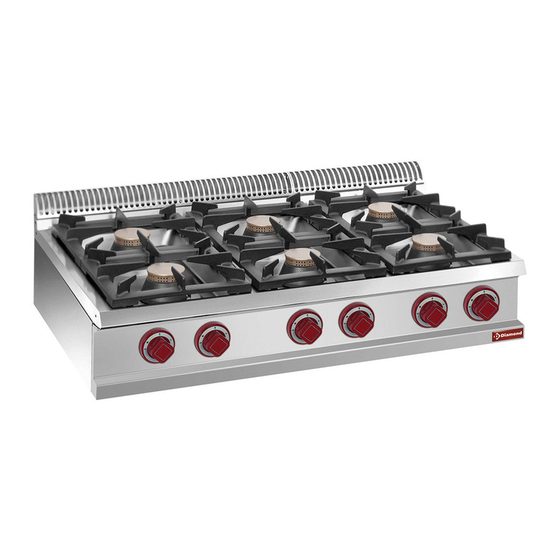
  • Seite 1 03/2007 Mod:G77/6F11T Production code:G77/6F11T...
  • Seite 2 Nach: EN 437 und EN 203 Teil 1 und 2 für Erdgas und Flüssiggas ENCIMERAS A GAS SERIE OPTIMA SEGÚN: EN 437 y EN 203 parte 1 y 2. Categoría II: Metano y G.P.L. G77/2F4T G77/4F7T G77/6F11T 0 6 9 4...
  • Seite 3: Inhaltsverzeichnis

    ITALIANO ....................pagina 2 - 11 ENGLISH ....................page 12 - 21 FRANÇAIS ....................page 22 - 31 DEUTSCH ....................Seite 32 - 41 ESPAÑOL ....................página 42 - 51 INDICE CAPITOLO DESCRIZIONE PAGINA Avvertenze generali ..........................Dati tecnici ............................Tabella I: Piani di cottura a gas serie OPTIMA Categoria II (Gas metano e G.P.L.) ......
  • Seite 4: Avvertenze Generali

    AVVERTENZE GENERALI - Leggere attentamente le avvertenze contenute nel presente libretto in quanto forniscono importanti indicazioni riguardanti la sicurezza di installazione, d’uso e di manutenzione. - Conservare con cura questo libretto per ogni ulteriore consultazione dei vari operatori. - Dopo aver tolto l’imballaggio, assicurarsi dell’integrità dell’apparecchiatura e in caso di dubbio, non utilizzare l’apparecchiatura e rivolgersi a personale professionalmente qualificato.
  • Seite 5: Dati Tecnici

    DATI TECNICI TABELLA I: PIANI DI COTTURA A GAS SERIE OPTIMA CATEGORIA II (GAS METANO e G.P.L.) MODELLO G77/2F4T G77/6F11T G77/4F7T Dimensioni esterne Tipo Larghezza 1100 Profondità Altezza Altezza massima G1/2" Attacco gas “A” G1/2" G1/2" Dimensioni piastra cottura –...
  • Seite 6: Istruzioni Per L'installazione

    PIASTRA DI COTTURA PIASTRA di cottura in acciaio speciale ad alta coducibilità termica. RISCALDAMENTO a gas mediante bruciatore in acciaio inossidabile a fiamma autostabilizzata che garantisce un’elevata uniformità di riscaldamento della piastra. Regolazione termostatica della temperatura con valvola di sicurezza e termocoppia per l’interruzione dell’afflusso del gas in caso di spegnimento accidentale del bruciatore pilota.
  • Seite 7: Posizionamento

    POSIZIONAMENTO - Le varie apparecchiature possono essere installate singolarmente o possono essere accoppiate ad altre apparecchiature della nostra stessa gamma. - Questa apparecchiatura non è idonea per l’incasso. - La distanza dalle pareti laterali deve essere minimo di 10 cm , nel caso in cui la distanza fosse inferiore o il materiale delle pareti o del pavimento fossero infiammabili, è...
  • Seite 8: Collegamento All'impianto Del Gas

    TABELLA II: DATI TECNICI GAS, PRESSIONE, UGELLI BRUCIATORE PIASTRA DI LENTA COTTU- RA, PILOTA E VITE DEL MINIMO ( PIANI DI COTTURA SERIE OPTIMA) Nazione Cat. Tipo PRESSIONE GAS BRUCIATORE BY-PASS PILOT A Press. Gas Portata Consumo UGELLO A MONTE mbar PIASTRA (21 S) all’Ugello...
  • Seite 9: Controlli

    CONTROLLI CONTROLLO DELLA PRESSIONE A MONTE (Pe) fig.1 La pressione viene misurata con un manometro 0÷80 mbar (Precisione almeno 0,1 mbar). La presa di pressione fig. 1 si trova sulla rampa gas G1/2” dietro il cruscotto; svitare la vite (A) della presa di pressione (B), attaccare la gomma al silicone nel manometro, accendere il bruciatore e rilevare la pressione “dinamica”...
  • Seite 10: Trasformazione Per Funzionamento Ad Altro Tipo Di Gas

    TRASFORMAZIONE PER FUNZIONAMENTO AD ALTRO TIPO DI GAS PIANO DI COTTURA - Togliere le griglie, spartifiamma e il corpo bruciatore. - Togliere le manopole - Smontare il frontalino SOSTITUZIONE UGELLO BRUCIATORE DI PLACCA Sostituire l’ugello (fig. 2 pos. 2) del bruciatore (chiave del 12) con quello corrispondente al tipo di gas prescelto attenendosi alle Tabelle II.
  • Seite 11: Sostituzione Dei Componenti Più Importanti

    Per accendere il bruciatore ruotare la manopola in posizione ( ) per il massimo ed in posizione ( ) per il minimo. Per spegnere completamente i bruciatori, portare la manopola in posizione (0). ACCENSIONE BRUCIATORI PIASTRA DI COTTURA - Per accendere il pilota della piastra di cottura, premere la manopola (fig. 8) ruotandola verso sinistra fino al simbolo ( ) raggiunta la posizione premere a fondo e procedere all’accensione del pilota schiacciando contemporaneamente il pulsan- te dell’accensione piezoelettrica;...
  • Seite 12: Manutenzione E Pulizia

    MANUTENZIONE E PULIZIA - Pulire giornalmente le parti in acciaio inox con acqua tiepida saponata, quindi risciacquare abbondantemente ed asciugare con cura. - Evitare nel modo più assoluto di pulire l’acciaio inox con paglietta, spazzole o raschietti d’acciaio comune in quanto possono depositare particelle ferrose che ossidandosi provocano punti di ruggine.
  • Seite 13 INDEX CHAPTER DESCRIPTION PAGE General remarks ........................... 13 Technical data ............................. 14 Table I: Gas cooktops OPTIMA series, Category II (Natural gas and L.P.G.) ........14 Technical characteristics ........................14 Installation instructions ........................15 Information about gas cooktops OPTIMA series ................15 Laws, regulations and technical directives to be complied with ............
  • Seite 14: General Remarks

    GENERAL REMARKS - Carefully read the instructions contained in the present booklet as they supply important information relating to safe installation, use and maintenance. - Keep this booklet with care, for any further consultation by the various operators. - Having removed the packing, make sure the unit is in good order and in case of doubt, do not use the unit, but call on skilled personnel.
  • Seite 15: Technical Data

    TECHNICAL DATA TABLE I: GAS COOKTOPS OPTIMA SERIES, CATEGORY II (NATURAL GAS AND L.P.G.) MODEL G77/2F4T G77/6F11T G77/4F7T Type External dimensions 1100 Width Depth Height Maximum Height “A” G1/2" G1/2" G1/2" Gas Connection Cooking Plate dimensions – – – Width –...
  • Seite 16: Installation Instructions

    GAS COCK of pressed brass, supplied with safety valve and thermocouple for automatic gas interruption in case of accidental pilot extinguishment. Adjustment between minimum and maximum capacity. COMBUSTION CHAMBER made of AISI 304 stainless steel insulated by way of ceramic fibres (Aluminium Oxide and Silicon Monoxide).
  • Seite 17: Installation Place

    INSTALLATION PLACE - The unit should be installed in adequately ventilated places. (This unit requires a draft of at least 2cu.m/hr l kW T.C. (Thermal Capacity). - Install the equipment in compliance with the safety rules applicable in the country where the equipment is installed. POSITIONING - The various units may be installed individually or together with other units of our range.
  • Seite 18 TABLE II: GAS TECHNICAL DATA, PRESSURE, MEDIUM BURNER NOZZLES, PILOT AND IDLE SCREW FOR GAS COOKTOPS OPTIMA SERIES Nation Cat. Type Gas pressure MEDIUM BY-PASS PILOT Nozzles Nominal Nozzle upstream BURNER (21 S) gas pressure Thermal consumption category mbar kW (1) 15°C 1013 mbar Ø...
  • Seite 19: Gas System Connection

    GAS SYSTEM CONNECTION - The unit should be supplied with gas having the characteristics and the pressure shown on Table II. - The gas pressure is measured at the initial pressure outlet with the burner on (see Fig. 1) - The unit is tested and fitted to operate with natural gas H G20 - 20mbar. * N.B.
  • Seite 20: Introduction To Users

    ADJUSTING THE MINIMUM THERMAL CAPACITY The right minimum for thermal capacity is achieved by means of the “calibrated” bypass idle screw firmly tightened in accordance with Table II Injectors Ch. 2.6 Ignite the burner according to Chapter 6 “Instructions to Users” in the maximum position ( );...
  • Seite 21: Cooking Plate

    COOKING PLATE REPLACING THE PILOT BURNER NOZZLE N.B.: We advise to first remove the spark plug because it can easily break. To change the pilot injector, you need to unscrew the nut (Fig. 6 position 7) with a size-10 spanner and replace the injector (Fig.
  • Seite 22: Replacing Important Components

    REPLACING IMPORTANT COMPONENTS The unit should be checked at least twice a year. You must check the burners, the ignition, the interignition, the maximum and minimum settings. REPLACING COMPONENTS To be performed exclusively by an “Authorised Service Centre”! In order to replace these components, it is important to first do the following: - Shut off the gas supply inlet valve;...
  • Seite 23 INDEX CHAPITRE DESCRIPTION PAGE Instructions generales .......................... 23 Donnees techniques ..........................24 Tableau I : Tables de cuisson au gaz serie OPTIMA Categorie I (Gaz methanE et G.P.L.) ....24 Caracteristiques techniques ........................ 24 Instructions pour l’installation ......................25 Plaquette d’identification de la table de cuisson au gaz serie OPTIMA ........... 25 Legislation a respecter ........................
  • Seite 24: Instructions Generales

    INSTRUCTIONS GENERALES - Lisez attentivement les instructions contenues dans cette notice car elles fournissent d’importantes indications concernant la sécurité d’installation, d’emploi et d’entretien. - Rangez soigneusement cette notice dans un endroit accessible et adapté à de futures consultations. - Après avoir déballé l’appareil, contrôlez-en l’intégrité. En cas de doute ne l’utilisez pas et adressez-vous à un personnel qualifié.
  • Seite 25: Donnees Techniques

    DONNEES TECHNIQUES TABLEAU 1 : TABLES DE CUISSON AU GAZ SERIE OPTIMA CATEGORIE I (GAZ METHANE et G.P.L.) MODEL G77/2F4T G77/6F11T G77/4F7T Type Dimensions externes 1100 Largeur Profondeur Hauteur Hauteur maximum “A” G1/2" G1/2" G1/2" Raccordement gaz Dimensions plaques de cuisson –...
  • Seite 26: Plaque Coupe-Feu

    PLAQUE COUPE-FEU PLAQUE de cuisson en acier spécial indéformable avec disque “zone de cuisson rapide” central extractible. BRULEUR en acier Inox AISI 304 avec flamme stabilisée, allumage par veilleuse “Targhet” et gicleurs fixes pour les différents types de gaz. ALLUMAGE piézo-électrique de la veilleuse. ROBINET en laiton étampé, équipé...
  • Seite 27: Lieu D'installation

    LIEU D’INSTALLATION - L’appareil doit être installé dans un local suffisamment aéré car il requiert une aspiration d’au moins 2 m /h . kW Débit thermique. - L’appareil doit être installé conformément à la législation en matière de sécutité en vigueur dans le pays d’installation. MISE EN PLACE - Cet appareil peut être installé...
  • Seite 28: Tableau Ii: Donnees Techniques Gaz, Pression, Gicleurs Bruleur Moyen, Veilleuse Et Vis Du Minimum (Table De Cuisson Serie Optima)

    TABLEAU II: DONNEES TECHNIQUES GAZ, PRESSION, GICLEURS BRULEUR MOYEN, VEILLEUSE ET VIS DU MINIMUM (TABLE DE CUISSON SERIE OPTIMA) PRESSION GAZ PAYS CATEGORIE TYPE DE PRESSION GAZ DEBIT THERMIQUE CONSOMMATION BRULEUR BY-PASS VEILLEUSE AU GIGLEUR EN AMONT mbar GICLEUR NOM. kW (1) GAZ (15°C) MOYEN (21 S)
  • Seite 29: Comment Obtenir Un Debit Thermique Nominal

    COMMENT OBTENIR UN DEBIT THERMIQUE NOMINAL Contrôlez si l’appareil est prédisposé pour le type de gaz, et si sa pression et sa catégorie correspondent au gaz disponible en réseau. L’indication est reportée sur l’emballage et/ou sur la plaquette d’identification de l’appareil. Si l’appareil est prédisposé...
  • Seite 30: Informations De L'usager

    CONTROLE POUR LE FONCTIONNEMENT AU GAZ LIQUIDE - Contrôlez que les gicleurs montés correspondent aux indications du tableau II paragraphe 2.6. - Vérifiez si la pression en entrée correspond aux indications du tableau II paragraphe 2.6. - Contrôlez que l’installation au gaz G.P.L. a deux régulateurs de pression de capacité suffisante et si la capacité d’évaporation est suffisante.
  • Seite 31: Plaque De Cuisson

    PLAQUE DE CUISSON CHANGEMENT DU GICLEUR DE LA VEILLEUSE Note : Démontez d’abord la bougie pour éviter de la casser. Pour changer le gicleur de la veilleuse, dévissez l’écrou (Fig.6 poste 7) avec une clé de 10 mm et démontez le gicleur (Fig. 6 poste 6) et remplacez-le par un autre correspondant au type de gaz choisi et reporté...
  • Seite 32: Changement Des Composants Plus Importants

    CHANGEMENT DES COMPOSANTS PLUS IMPORTANTS L’appareil doit être contrôlé tous les 6 mois. Il faut en particulier vérifier le brûleur, l’allumage, le réglage du minimum et du maximum, le bon fonctionnement de la hotte anti-refoulement et coupe tirage (Type B 11) ainsi que l’entrée de l’air. CHANGEMENT DES COMPOSANTS Attention ! Pour les réparations s’adresser seulement à...
  • Seite 33 INHALTSVERZEICHNIS KAPITEL BESCHREIBUNG SEITE Allgemeinehinweise ..........................33 Technische Daten ..........................34 Tabelle I: Gaskochstellen Serie OPTIMA Kategorie II (Methan Und Flüssiggas)......34 Technische Eigenschaften ........................34 Installationsanleitungen ........................35 Informationen Über Die Gaskochfelder Serie OPTIMA ..............35 Einzuhaltende Gesetze, Normen Und Technische Richtlinien ............35 Installationsort ............................
  • Seite 34: Allgemeinehinweise

    ALLGEMEINEHINWEISE - Dieses Handbuch enthält wichtige Anleitungen für eine sichere Installation, Verwendung und Wartung und muß daher aufmerksam durchgelesen werden. - Dieses Handbuch muß für ein späteres Nachschlagen der verschiedenen Bediener sorgfältig aufbewahrt werden. - Nach dem Entfernen der Verpackung muß das Gerät nach seinem einwandfreien Zustand überprüft werden; verwenden Sie im Zweifelsfall das Gerät nicht, sondern wenden Sie sich an eine qualifizierte Fachkraft.
  • Seite 35: Technische Daten

    TECHNISCHE DATEN TABELLE I: GASKOCHSTELLEN SERIE OPTIMA KATEGORIE II (METHAN und FLÜSSIGGAS) MODELL G77/2F4T G77/6F11T G77/4F7T Außenmaße 1100 Breite Tiefe Höhe Gesamthöhe G1/2" “A” G1/2" G1/2" Gasanschluß Kochplattenabmessungen – – – Breite – – – Tiefe Backofenabmessungen GN2/1 – –...
  • Seite 36: Installationsanleitungen

    GLÜHPLATTE PLATTE aus speziellem unverformbarem Stahl mit einer herausnehmbaren “Blitzkochzone” in der Mitte. BRENNER aus Inox-Stahl AISI 304 mit Flammenhaltung; Zündung durch “Targhet”-Leitflamme mit fixen Düsen für die verschiedenen Gasarten. PIEZOZÜNDUNG des Leitflammenbrenners. HAHN aus gedrucktem Messing, mit Sicherheitsventil und Thermoelement zur automatischen Gasabstellung bei unabsichtlichem Erlöschen der Leitflamme.
  • Seite 37: Installationsort

    INSTALLATIONSORT - Das Gerät muß in einem ausreichend durchlüftetem Raum installiert werden. (Dieses Gerät bedarf einer Absaugkraft von mindestens 2 m /h • kW Wärmeleistung). - Bei der Installation dieses Gerätes sind die Sicherheitsvorschriften des Landes einzuhalten, im dem das Gerät aufgestellt wird.
  • Seite 38: Anschluss An Die Gasanlage

    TABELLE II: TECHNISCHE DATEN ÜBER: GAS, DRUCK, DÜSEN DES MITTLEREN BRENNERS, LEITFLAMME UND KLEINSTSTUFEN-EINSTELLSCHRAUBE GASKOCHFELDER SERIE OPTIMA GASDRUCK AN LAND BY-PASS DÜSEN- GAS-VORDRUCK MITTLERER LEIT- GASVERBRAUCH NENNWÄRME- GASART DER DÜSE MIT BRENNER KATEGORIE mbar (15°C) FLAMME LEISTUNG kW (1) (21 S) 21 S Mind.
  • Seite 39: Erreichen Der Nennwärmeleistung

    ABGASUNG IN EINE RAUCHHAUBE. GERÄTTYP: A Das Gasgerät muß unter einer Rauchhaube mit normengerechten Anlageneigenschaften aufgestellt werden. (Dieses Gerät bedarf einer Absaugkraft von mindestens 2 m3/h • kW Wärmeleistung). Die Küchendurchlüftung kontrollieren: sie muß den geltenden Normen entsprechen. ERREICHEN DER NENNWÄRMELEISTUNG Kontrollieren Sie, ob das Gerät für die den Gasnetzwerten entsprechende Gasart, Druck und Kategorie voreingestellt ist.
  • Seite 40: Vorbereitung Des Verwenders

    Den Druck an der Düse und die Mindestwärmeleistung überprüfen. Bei der 2. und 3. Familie muß die Kleinststufen-Einstellschraube (By-Pass) ganz in den Hahn (Abb. 2 Pos. 1) und in den Thermostat (Abb. 5 Pos. 11) eingeschraubt werden. KONTROLLE FÜR DEN BETRIEB MIT FLÜSSIGGAS Kontrollieren, ob die montierten Düsen mit den Werten in den Tabellen II Kap.
  • Seite 41: Kochplatte

    KOCHPLATTE AUSTAUSCHEN DER LEITFLAMMENBRENNERDÜSE MERKE: Es wird empfohlen, die sofort Glühkerze abzunehmen, damit sie nicht bricht. Zum Austauschen der Leitflammen- Einspritzdüse die Mutter (Abb. 6 Pos. 7) mit einem 10er-Schlüssel losschrauben und die Einspritzdüse (Abb. 6 Pos. 6) mit der für den gewählten Gastyp entsprechenden Düse ersetzen (siehe hierzu die Angaben in der Tabelle II Einspritzdüsen Kap.
  • Seite 42: Austauschen Der Wichtigsten Bestandteile

    AUSTAUSCHEN DER WICHTIGSTEN BESTANDTEILE Das Gerät muß mindestens zweimal pro Jahr kontrolliert werden. Zu kontrollieren sind: die Brenner, die Zündung, die Zwischenzündung, die Einstellung der Kleinst- und Höchststufe. Außerdem muß die Funktionstüchtigkeit der Wind- und Zugunterbrechungsschutzhaube (Typ B 11 ) und die Zuluft kontrolliert werden. AUSTAUSCHEN DER BESTANDTEILE Durchführung nur durch befugte technische Betreuungsstellen! Vor dem Austauschen nachfolgender Bestandteile:...
  • Seite 43 ÍNDICE CAPÍTULO DESCRIPCIÓN PÁGINA Observaciones generales ........................43 Datos técnicos ............................ 44 Tabla 1: Encimeras a gas serie OPTIMA, Categoría II (Gas metano y GPL) ........44 Características técnicas ........................44 Instrucciones para la instalación ......................45 Informaciones sobre las planchas a gas serie OPTIMA ............... 45 Ley, normas y directivas técnicas a respetar ..................
  • Seite 44: Observaciones Generales

    OBSERVACIONES GENERALES - Leer atentamente las observaciones contenidas en el presente manual ya que suministran importantes indicaciones respecto a la seguridad de instalación, de uso y de mantenimiento. - Conservar con cuidado el presente manual para cualquier consulta posterior de los distintos operadores - Después de haber quitado el embalaje, asegurarse que el aparato esté...
  • Seite 45: Datos Técnicos

    DATOS TÉCNICOS TABLA 1: ENCIMERAS A GAS SERIE OPTIMA, CATEGORÍA II (GAS METANO y GPL) MODELO G77/2F4T G77/4F7T G77/6F11T Dimensiones exteriores 1100 Anchura Profundidad Altura Altura máxima “A” G1/2" G1/2" G1/2" Toma del Gas Dimensiones plancha – – – Anchura –...
  • Seite 46: Instrucciones Para La Instalación

    INSTRUCCIONES PARA LA INSTALACIÓN La instalación y la eventual transformación para el uso con otros tipos de gas tiene que ser efectuada por personas expertas, según las normas en vigor. (Véanse las tablas de datos técnicos 1.1 y 2.6). OBSERVACIONES: En caso de que el aparato se instale contra una pared, esta última tiene que resistir a los valores de temperatura de 80°C y debe ser incombustible.
  • Seite 47: Montaje Aparatos Top Sobre Bases O Soportes Voladizos

    MONTAJE APARATOS TOP SOBRE BASES O SOPORTES VOLADIZOS Todas las cocinas constan de patas de altura regulable (P): - Cuando se trata de un aparato de sobremesa, hay que enroscar o desenroscar las patas (P) como se indica en la figura hasta que se apoye perfectamente, luego apretar la contratuerca (D) para bloquear la pata.
  • Seite 48: Conexión De La Instalación Del Gas

    TABLA II: DATOS TÉCNICOS GAS, PRESIÓN, INYECTORES QUEMADOR PLANCHA, PILOTO Y TORNILLO DEL MÍNIMO (PLANCHAS SERIE OPTIMA). PRESÍON GAS AL CAPACIDAD PAÍSY TIPO DE PRESÍON GAS ANTERIOR QUEMADOR BY-PASS CATEGORÍA CONSUMO GAS PILOTO INYECTOR CON TÉRMICA NOM. CATEGORÍA INYECTOR AL APARATO mbar PLANCHA (15°C) (21 S)
  • Seite 49: Controles

    CONTROLES CONTROL DE LA PRESIÓN ANTERIOR AL APARATO (Pe) Fig. 1 La presión se mide con un manómetro 0 • 80 mbar (Presión de por lo menos 0,1 mbar). La toma de presión Fig. 1 se encuentra en la conexión del gas G 1/” detrás del tablero: desatornillar el tornillo (A) de la toma de presión (B), conectar la manguera de siliconas en el manómetro, encender el quemador y medir la presión “dinámica”...
  • Seite 50: Transformación Para El Funcionamiento Con Otro Tipo De Gas

    3. TRANSFORMACIÓN PARA EL FUNCIONAMIENTO CON OTRO TIPO DE GAS PLANCHAS DE COCCIÓN - Quitar las parrillas, el partidor de llama y el cuerpo del quemador - Quitar las manivelas - Desmontar la parte frontal. SUSTITUCIÓN DEL INYECTOR DEL QUEMADOR DE LA MESA DE TRABAJO Sustituir el inyector (Fig.
  • Seite 51: Intrucciones Para El Usuario

    INTRUCCIONES PARA EL USUARIO ENCENDIDO QUEMADOR DE PLACA (COCINA) - Para encender el piloto de la cocina, apretar la manivela (Fig. 7) girándola hacia la izquierda hasta el símbolo ( ), ya en la posición apretar a fondo y encender el piloto. Mantener apretada la manivela unos 20 segundos; al soltarla la llama del piloto tiene que quedar encendida, si así...
  • Seite 52: Mantenimiento

    - montar un nuevo termopar del mismo tipo siguiendo el orden inverso al del montaje. B) Grifo quemador mesa de trabajo (Fig. 2). - desmontar la tuerca (3) con una llave del 9; - desmontar todas las tomas del gas (4-5-6) - montar un nuevo grifo siguiendo el orden inverso al del desmontaje.
  • Seite 53: Schemi Di Installazione

    SCHEMI DI INSTALLAZIONE INSTALLATION DIAGRAMS SCHEMAS D’INSTALLATION INSTALLATIONSPLÄNE ESQUEMAS DE INSTALACIÓN G77/2F4T G77/4F7T G77/6F11T Ø 17mm H=15/20 mm A) attacco gas G1/2” gas connection G1/2” Raccord gaz G1/2” Gasanschluß G1/2” Toma de gas G 1/2” - 52 -...
  • Seite 54 Fig. 2 Fig. 3 Fig. 1 Fig. 7 Fig. 6 - 53 -...
  • Seite 55 INFORMAZIONE AGLI UTENTI AI SENSI delle Direttive 2002/95/CE, 2002/96/CE e 2003/108/CE, relative alla riduzione dell’uso di sostanze pericolose nelle apparecchiature elettriche ed elettroniche, nonché allo smaltimento dei rifiuti. Il simbolo del cassonetto barrato riportato sull’apparecchiatura o sulla confezione, indica che il prodotto alla fine della propria vita utile deve essere raccolto separatamente dagli altri rifiuti.

Diese Anleitung auch für:

G77/6f11tG77/4f7t

Inhaltsverzeichnis