Herunterladen Inhalt Inhalt Diese Seite drucken
Sony HVBK-1520 Installationsanleitung

Sony HVBK-1520 Installationsanleitung

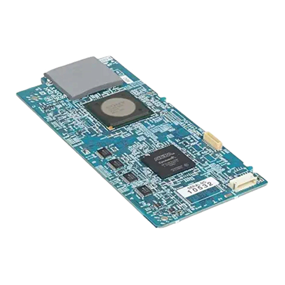
Format converter board

Werbung

Verfügbare Sprachen
  • DE

Verfügbare Sprachen

  • DEUTSCH, seite 70
Printed in Japan
Format Converter
Board
設置説明書
2 ページ
Installation Instructions
Page 22
Manuel d'installation
Page 46
Installationsanleitung
Seite 70
Istruzioni per l'installazione
Instrucciones de instalación
お買い上げいただきありがとうございます。
電気製品は安全のための注意事項を守らないと、
火災や人身事故になることがあります。
• ご使用にあたっては、デジタル HD ビデオカセットレコーダー
本体に付属の取扱説明書の「安全のために」と「
」をよくお読みください。お読みになったあとは、い
つでも見られるところに必ず保管してください。
• 本基板の取り付けは、必ずお買い上げ店またはソニーのサービ
ス窓口にご依頼ください。
HVBK-1520
© 2007 Sony Corporation
3-275-323-04(1)
JP
GB
FR
DE
IT
Pagina 95
ES
Pagina 119
」 、

Werbung

Inhaltsverzeichnis
loading

Inhaltszusammenfassung für Sony HVBK-1520

  • Seite 1 Manuel d’installation Page 46 Installationsanleitung Seite 70 Istruzioni per l’installazione Pagina 95 Instrucciones de instalación Pagina 119 お買い上げいただきありがとうございます。 電気製品は安全のための注意事項を守らないと、 火災や人身事故になることがあります。 • ご使用にあたっては、デジタル HD ビデオカセットレコーダー 本体に付属の取扱説明書の「安全のために」と「 」 、 「 」をよくお読みください。お読みになったあとは、い つでも見られるところに必ず保管してください。 • 本基板の取り付けは、必ずお買い上げ店またはソニーのサービ ス窓口にご依頼ください。 HVBK-1520 Printed in Japan © 2007 Sony Corporation...
  • Seite 2: Inhaltsverzeichnis

    日本語 目次 概要 ..................3 コンバート機能について ..........4 追加されるセットアップメニュー項目 ......6 HVBK-1520 の構成品 ............. 11 お客様へ ................12 取り付け ................13 目次...
  • Seite 3 概要 フォーマットコンバーターボード HVBK-1520 は、ソニーデ ジタル HD ビデオカセットレコーダー HVR-1500/1500A に装 着して使用するオプション基板です。 本基板を装着することにより、HVR-1500/1500A の HD-SDI 出力の機能を以下のように拡張することができます。 ご注意 • 本基板を装着するには、HVR-1500/1500A のファームウェ アのアップグレードが必要な場合があります。 • SD 出力と HD 出力は同時に出力されますが、 コンバートさ れた HD-SDI 出力は SD 出力に対して 1 フレーム遅延しま す。 ◆ 本基板の装着および HVR-1500/1500A のファームウェアのアップグ レードについては、ソニーのお買い上げ店またはサービス窓口にお問 い合わせください。 アップコンバート機能...
  • Seite 4: コンバート機能について

    お使いになる前に、必ず動作確認を行ってください。故障 その他に伴う営業上の機会損失等は保証期間中および保証 期間経過後にかかわらず、補償はいたしかねますのでご了 承ください。 コンバート機能について 本基板が対応するコンバート機能により、次表に示すような 信号変換が行われます。 システム周波数が 59.94i(29.97Hz)の場合 入力信号 HD-SDI 出力信号 テープの再生 E-E モード時 ライン設定 1080i ライン設定 720p 信号 の入力信号 コンバート ディレイ コンバート ディレイ モード (フレーム) モード (フレーム) − アナログ / 720 × 480 720 × 480 59.94i t 59.94i t 1920 ×...
  • Seite 5 システム周波数が 50i(25Hz)の場合 入力信号 HD-SDI 出力信号 テープの再生 E-E モード時 ライン設定 1080i ライン設定 720p 信号 の入力信号 コンバート ディレイ コンバート ディレイ モード (フレーム) モード (フレーム) − アナログ / 720 × 576 720 × 576 50i t 50i t 1920 × 1080 1280 × 720 DV / −...
  • Seite 6: 追加されるセットアップメニュー項目

    追加されるセットアップメニュー項目 本基板を HVR-1500/1500A に装着すると、HVR-1500/1500A のセットアップメニューに以下の項目が追加されます。 ◆ メニューの操作方法については、HVR-1500/1500A の取扱説明書をご 覧ください。 • 「*」に続けて示す設定(たとえば「* EE」 )は、工場出 荷時の設定を表します。 • HVR-1500/1500A のタイムカウンター表示部には、現在の メニュー階層に応じて、1 ∼ 3 個の「>」記号が表示され ます。下の階層になるほど、 「>」の数が増えます。 UP/CROSS CONVERTER [Up/Cross]: 設定内容 アップコンバート / クロスコンバート機能に関 する設定 LINE SELECT [> Line Sel]:ライン設定を * 1080i [>> 1080i]:1080i 選択する。...
  • Seite 7 UP/CROSS CONVERTER [Up/Cross]: 設定内容 アップコンバート / クロスコンバート機能に関 する設定 AUTO ASPECT [> Auto Aspct]:SD 信号 * ON [>> ON]:SD 信号に付加されたアスペ に含まれているアスペクト識別信号の取 クトフラグに従って、アップコンバート時 り扱いについて設定する。 の表示モードを自動設定する。 OFF [>> OFF]:MANUAL ASPECT の設定 ご注意 に従う(SD 信号に付加されたアスペクト ON に設定したときにアスペクト識別信号が検 フラグに従わない) 。 出されない場合は、MANUAL ASPECT の設 定に従います。 MANUAL ASPECT [>Manual Asp]:アッ *...
  • Seite 8 UP/CROSS CONVERTER [Up/Cross]: 設定内容 アップコンバート / クロスコンバート機能に関 する設定 UP CON PROCESS [> Upcon Proc]:SD FIELD [>> Field]:SD から HD への変換時に から HD へアップコンバートするときの 使用する元画としてフィールド画を使用す 元画について設定する。 る。 FRAME [>> Frame]:SD から HD への変換 時に使用する元画としてフレーム画を使用 する。 * ADAPTIVE(標準モード) [>> Adaptive]:SD から HD への変換時に使 用する元画としてフレーム画またはフィー...
  • Seite 9 UP/CROSS CONVERTER [Up/Cross]: 設定内容 アップコンバート / クロスコンバート機能に関 する設定 IMAGE DETAIL GAIN [>> 0 [>>> 0] ∼ 40H [>>> 40H] ∼ 7FH ENHANCER Dtil Gain]:輪郭 [>>> 7FH] [> Image を強調するときの 工場出荷時:* 40H Enh]:アップコ 鮮鋭度を調整す ンバート / クロ る。 スコンバートの LIMITER [>> 0 [>>>...
  • Seite 10 a) EDGE-CROP 4:3 16:9 b) LETTER BOX 4:3 16:9 c) SQUEEZE 4:3 16:9 概要...
  • Seite 11: Hvbk-1520 の構成品

    HVBK-1520 の構成品 HVBK-1520 は、以下に示す品目で構成されています。 取り付けに必要な構成品 VNS-2 基板 六角支柱(φ 2、L=7mm、1 本) ネジ(+ PSW2 × 5、4 本) ネジ(M3、2 本) 配線止め(1 本) GF シート HVR-1500 には使用しない 概要...
  • Seite 12: お客様へ

    取り付けに使用しない構成品 • HVR-1500 に取り付ける場合 HVR-1500 を日本国内で使用する場合、下図の付属品は使用 しません。 • HVR-1500A に取り付ける場合 下図の付属品は使用しません。 フェライトコア クリップ 両面テープ イーバリアー(DDE1) イーバリアー(DDE2) お客様へ 13 ページ以降の設置説明( 「取り付け」の項)は、特約店お よびソニーのサービス窓口用の設置説明書です。 お客様がこの設置説明書に記載された作業を行うと、火災 や、感電やけがなど人身事故につながることがあります。お 客様自身では絶対に取り付け作業をしないでください。 本基板の取り付けは、必ずお買い上げ店またはソニーのサー ビス窓口にご依頼ください。 お客様へ...
  • Seite 13: 取り付け

    取り付け 本基板を取り付ける手順は以下のとおりです。 作業を行う前に、必ず電源をお切りください。 以下の手順の図は HVR-1500A です。 ご注意 • 本基板を取り付ける HVR-1500 本体の基板には、DPR 基板 と SDI 基板の 2 種類があります。どちらの場合でも同様の 手順で取り付けることができます。 • 本基板の装着には、HVR-1500/1500A 本体のファームウェ アのアップグレードが必要です。詳しくはお買い上げ店ま たはソニーのサービス窓口にお問い合わせください。 • リアパネルや CN-2905 基板を取りはずしたときに、ネジや 基板をなくさないように保管してください。 HVR-1500/1500A のリアパネルを固定しているネジ (HVR-1500:8 箇所、HVR-1500A:14 箇所)をはずす。 取り付け...
  • Seite 14 i.LINK コネクター (CN1968A 基板 CN2) からコネクター ケーブルをはずし、リアパネルを取りはずす。 コネクターケーブル i.LINK コネクター 上から 3 番目のスロットに装着されている SDI 基板 (HVR-1500 のみ)または DPR 基板を矢印の方向へ引き 出す。 取り付け...
  • Seite 15 SDI 基板 (HVR-1500 のみ) または DPR 基板に本基板を装 着する。 DPR 基板の場合 HVR-1500A の DPR 基板に本基板を装着する場合は、GF シートを取り付ける必要があります(手順 5 ∼ qa) 。 CN-2905 基板 DPR 基板 本基板 六角支柱 a ネジ 2 本をはずして、CN-2905 基板を取りはずす。 b 付属の六角支柱を、 付属の +PSW2 × 5 ネジを使って DPR 基板の裏面からネジ止めする。 c 手順 で...
  • Seite 16 d 付属の +PSW2 × 5 ネジ 3 本で本基板を固定する。 HVR-1500 を使用している場合は、手順 に進む。 e GF シートに貼られた両面テープの剥離紙をはがす。 f GF シートの両面テープの貼られた面を下にし(1) 、GF シートの端と放熱シートの端 A を合わせて、GF シート を放熱シートに貼り付ける(2) 。 GF シート 放熱シート g GF シートの端と DPR 基板のブラケットの端 A を合わせ て、GF シートを DPR 基板のブラケットに貼り付ける (1) 。 このとき...
  • Seite 17 h 付属の M3 ネジ 1 本を A のネジ穴に締め込み、 GF シートを 固定する。 i 配線止めの輪の部分(1)と被覆部分(2)の角度が 10 ° 以上になるように、配線止めを折り曲げる。 10°以上 配線止め j 配線止めの輪の部分を GF シートのネジ穴(1)に合わ せ、被覆部分(2)を放熱シートに押しつけてシートを 押さえる。 取り付け...
  • Seite 18 k もう 1 本の M3 ネジ (付属) を締め込み、 GF シートと配線 止めを固定する。 取り付け...
  • Seite 19 SDI 基板の場合(HVR-1500 のみ) CN-2905 基板 SDI 基板 本基板 六角支柱 a ネジ 2 本をはずして、CN-2905 基板を取りはずす。 b 付属の六角支柱を付属の+PSW2×5ネジを使ってSDI基板 の裏面からネジ止めする。 c 手順 で CN-2905 基板を取りはずした位置に本基板を押し 付け、本基板の裏面の端子と SDI 基板上の端子をかん合 させる。 d 付属の +PSW2 × 5 ネジ 3 本で本基板を固定する。 取り付け...
  • Seite 20 両サイドのガイドに合わせて、本基板を装着した SDI 基 板(HVR-1500 のみ)または DPR 基板を HVR-1500/ 1500A に差し込み、装着する。 このとき、コネクターケーブルが HVR-1500/1500A 内部 に引き込まれないように、リア側に引き出して保持して おく。基板端のコネクターパネルの位置決め穴に、リア フレームのダボを合わせて押し込む。 ダボ ガイド 位置決め穴 位置決め穴 取り付け...
  • Seite 21 リアパネルの i.LINK コネクターをコネクターケーブルに 接続する。 コネクターケーブル i.LINK コネクター 手順 で取りはずしたネジを使ってリアパネルを固定す る。 取り付け...
  • Seite 22 E1 (residential), E2 (commercial and light industrial), E3 (urban outdoors), E4 (controlled EMC environment, ex. TV studio). The manufacturer of this product is Sony Corporation, 1-7-1 Konan, Minato-ku, Tokyo, Japan. The Authorized Representative for EMC and product safety is Sony...
  • Seite 23 Table of Contents Overview................24 About the Conversion Function ........25 Additional Setup Menu Items .........26 Components supplied with the HVBK-1520 ....31 Installation................32 For Customers in Europe (HVR-1500 only) ....41 Table of Contents...
  • Seite 24: Overview

    Overview The HVBK-1520 HD Format Converter Board is an optional board for installation in the Sony HVR-1500/1500A Digital HD Videocassette Recorder. Installing this board extends the HD-SDI output functions of the HVR- 1500/1500A in the following way. Notes • SD and HD signals are output simultaneously, but the converted HD- SDI output is delayed one frame with respect to SD output.
  • Seite 25: About The Conversion Function

    About the Conversion Function The conversion function supported by this board provides the signal conversions shown in the following table. When the system frequency is 59.94i (29.97 Hz) Input signal HD-SDI output signal Tape Input signal Line select 1080i Line select 720p playback in E-E mode Convert mode...
  • Seite 26: Additional Setup Menu Items

    Note The following restrictions apply to the conversion function of this board. • For up-converted or cross-converted signal output, only HD-SDI output is available. For component HD output and i.LINK HDV output, the signals are output in the same format as that recorded on the tape in accordance with the HVR-1500/1500A specification.
  • Seite 27 UP/CROSS CONVERTER [Up/Cross]: Description of settings Settings relating to the up-conversion/ cross-conversion function TIME CODE [> Time 9P TC PHASE [>> SD [>>> SD]: Align with SD phase. Code]: Set 9P TC Phs]: HD [>>> HD]: Align with HD phase. timecode.
  • Seite 28 UP/CROSS CONVERTER [Up/Cross]: Description of settings Settings relating to the up-conversion/ cross-conversion function POSITION ADJUST H CROP POS [>> H 0H [>>> 0H] to 80H [>>> 80H] to FFH [> Pos Adjust]: Crp pos]: In [>>> FFH]: Adjust in 2-pixel units in When edge crop edge crop the range ±240 pixels from the center.
  • Seite 29 UP/CROSS CONVERTER [Up/Cross]: Description of settings Settings relating to the up-conversion/ cross-conversion function IMAGE ENHANCER DETAIL GAIN [>> 0 [>>> 0] to 40H [>>> 40H] to 7FH [>>> [> Image Enh]: Dtil Gain]: 7FH] Adjust image Adjust the Factory default: enhancer for up- degree of conversion and...
  • Seite 30 UP/CROSS CONVERTER [Up/Cross]: Description of settings Settings relating to the up-conversion/ cross-conversion function BACKGROUND COL [> BG Color]: Set BLACK [>> BLACK]: Set to black. the color of the background (where GRAY [>> GRAY]: Set to gray. there is no image). BLUE [>>...
  • Seite 31: Components Supplied With The Hvbk-1520

    Components supplied with the HVBK-1520 The HVBK-1520 is supplied with the following items. VNS-2 board Hexagonal pillar (length 7 mm, Screws (+PSW 2×5, quantity 4) diameter 2 mm, quantity 1) Screws Wire holder Graphite sheet (M3, quantity 2) (quantity 1)
  • Seite 32: Installation

    • Installing this board requires an upgrade of the HVR-1500/1500A main unit firmware. For details, contact your Sony dealer or a Sony sales representative. • When removing the rear panel or the CN-2905 board, be careful not to lose the board or screws.
  • Seite 33 Disconnect the connector cable from the i.LINK connector (CN2 on the CN1968A board), then remove the rear panel. Connector cable i.LINK connector Pull out the SDI (for HVR-1500) or DPR board in the third slot from the top in the direction of the arrow. Installation...
  • Seite 34 Mount this board on the SDI (for HVR-1500) or DPR board. For the DPR board To mount this board on the DPR board of the HVR-1500A, you must install the graphite sheet (steps 5 to qa). CN-2905 board DPR board This board Hexagonal pillar 1 Remove the two screws, and remove the CN-2905 board.
  • Seite 35 5 Remove the backing from the double-sided tape that is affixed to the graphite sheet. 6 Align the edge of the graphite sheet to the edge A of the heat conducting sheet, with the double-sided tape side of the graphite sheet (1) down, and affix the graphite sheet to the heat conducting sheet (2).
  • Seite 36 8 Secure the graphite sheet by screwing one of the supplied M3 screws into the screw hole A. 9 Bend the wire holder so that the angle between the sheathed part (2) and the ring part (1) is at least 10°. 10°...
  • Seite 37 qa Secure the graphite sheet and wire holder by screwing in the other supplied M3 screw. Installation...
  • Seite 38 For the SDI board (for HVR-1500) CN-2905 board SDI board This board Hexagonal pillar 1 Remove the two screws, and remove the CN-2905 board. 2 Attach the supplied hexagonal pillar, using the supplied screw (+PSW 2 × 5) from the underside of the motherboard. 3 Mount this board in the position from which you removed the CN-2905 board in step 1, so that the connectors on the underside of this board engage with the connectors on the SDI board.
  • Seite 39 Align the SDI (for HVR-1500) or DPR board on which this board is mounted with the guides on both sides of the HVR-1500/1500A, and push it firmly in. To prevent the i.LINK connector cable from being trapped within the HVR-1500/1500A, pull it out toward the rear panel, and hold it.
  • Seite 40 Reconnect the rear panel i.LINK connector to the connector cable. Connector cable i.LINK connector Using the screws removed in step 1 fasten the rear panel. Installation...
  • Seite 41: For Customers In Europe (Hvr-1500 Only)

    For Customers in Europe (HVR-1500 only) When using this board, use the following procedure to install the supplied ferrite core and electromagnetic shielding in the HVR-1500. To attach the ferrite core Remove the two fixing screws holding the cover on the bottom of the HVR-1500, and remove the cover.
  • Seite 42 Disconnect the ribbon cable as follows. Release the lock of the connector (1), and pull out the ribbon cable (2). Ribbon cable Attach the supplied double-sided tape in position 1. Double-side tape Installation...
  • Seite 43 Pass the ribbon cable disconnected in step 2 through the ferrite core. Ferrite core Installation...
  • Seite 44 Fix the ferrite core with the supplied clip, and reconnect the ribbon cable as follows. Insert the ribbon cable into the connector (1), and lock the connector (2). Clip Position the ferrite core over the double-sided tape applied in step 3, and press the ferrite core against the tape.
  • Seite 45 To apply the electromagnetic shielding Remove the eight screws holding the rear panel of the HVR-1500. Peel off the protective layer from the double-sided tape attached to the electromagnetic shielding. Apply the electromagnetic shielding in the positions on the inner side of the rear panel, as shown in the figure.
  • Seite 46 E4 (environnement EMC contrôlé, ex. studio de télévision). Le fabricant de ce produit est Sony Corporation, 1-7-1 Konan, Minato- ku, Tokyo, Japon. Le représentant autorisé pour EMC et la sécurité des produits est Sony Deutschland GmbH, Hedelfinger Strasse 61, 70327 Stuttgart, Allemagne.
  • Seite 47 Sommaire Aperçu..................48 A propos de la fonction de conversion ......49 Eléments supplémentaires du menu de configuration ..50 La carte HVBK-1520 comprend les éléments suivants ...55 Installation................56 Pour les clients européens (Pour le modèle HVR-1500) .65 Sommaire...
  • Seite 48: Aperçu

    Aperçu La carte de conversion de format HVBK-1520 HD est une carte optionnelle pour l’installation dans l’enregistreur HD numérique HVR-1500/1500A de Sony. L’installation de cette carte augmente les fonctions de sortie HD-SDI du HVR-1500/1500A de la manière suivante. Remarques • Les signaux SD et HD sortent simultanément, mais la sortie HD-SDI est retardée d’une image par rapport à...
  • Seite 49: A Propos De La Fonction De Conversion

    A propos de la fonction de conversion La fonction de conversion prise en charge par cette carte permet les conversions de signaux indiquées dans le tableau suivant. Lorsque la fréquence de système est 59.94i (29.97 Hz) Signal d’entrée Signal de sortie HD SDI Format de Signal Sélection de lignes 1080i Sélection de lignes 720p...
  • Seite 50: Eléments Supplémentaires Du Menu De Configuration

    Remarque Les restrictions suivantes s’appliquent à la fonction de conversion de cette carte. • Pour la sortie en up-conversion ou cross-conversion, seule la sortie HD-SDI est disponible. Pour la sortie HD composante et la sortie HDV i.LINK, les signaux sont émis dans le même format que celui de l’enregistrement sur la bande, selon la caractéristique du HVR-1500/1500A.
  • Seite 51 UP/CROSS CONVERTER [Up/Cross] : Description des réglages Réglages relatifs à la fonction de up- conversion/cross-conversion LINE SELECT [> Line Sel]: Sélectionnez 1080i [>> 1080i]: 1080i le réglage de ligne. 720p [ >> 720p]: 720p THRU MODE DELAY [> Thru delay]: Pour OFF [>>...
  • Seite 52 UP/CROSS CONVERTER [Up/Cross] : Description des réglages Réglages relatifs à la fonction de up- conversion/cross-conversion POSITION ADJUST H CROP POS [>> H 0H [>>> 0H] à 80H [>>> 80H] à FFH [>>> [> Pos Adjust] : Crp pos] : En FFH] : Ajustez en unités de 2 pixels Lorsque le mode de...
  • Seite 53 UP/CROSS CONVERTER [Up/Cross] : Description des réglages Réglages relatifs à la fonction de up- conversion/cross-conversion IMAGE ENHANCER DETAIL GAIN [>> 0 [>>> 0] à 40H [>>> 40H] à 7FH [>>> [> Image Enh] : Dtil Gain] : 7FH] Ajustez le Ajustez le Réglage par défaut : correcteur...
  • Seite 54 UP/CROSS CONVERTER [Up/Cross] : Description des réglages Réglages relatifs à la fonction de up- conversion/cross-conversion IMAGE ENHANCER H/V RATIO [>> H/V 0 [>>> 0] à 03H [>>> 03H] à 7H [>>> 7H] [> Image Enh] : Ratio] : Ajustez Réglage par défaut : Ajustez le le rapport correcteur...
  • Seite 55: La Carte Hvbk-1520 Comprend Les Éléments Suivants

    La carte HVBK-1520 comprend les éléments suivants La HVBK-1520 est fournie avec les pièces suivantes. Carte VNS-2 Pilier hexagonal (longueur 7 mm, Vis (+PSW 2×5, quantité 4) diamètre 2 mm, quantité 1) Enrouleur de fil Feuille de (M3, quantité 2) électrique (quantité...
  • Seite 56: Installation

    à des blessures ou à des dommages pour les éléments périphériques. Pour éviter de tels risques, faites faire l’installation par un personnel de service qualifié. Procédez comme suit pour installer la carte HVBK-1520 dans le HVR-1500/1500A. Veillez à bien mettre hors tension avant de commencer le travail.
  • Seite 57 Débranchez le câble de connecteur du connecteur i.LINK (CN2 sur la carte CN1968A), puis retirez le panneau arrière. Câble de connecteur Connecteur i.LINK Retirez la carte SDI (pour le modèle HVR-1500) ou DPR du troisième emplacement à partir du dessus dans le sens de la flèche. Montez cette carte sur la carte SDI (pour le modèle HVR-1500) ou DPR.
  • Seite 58 Pour la carte DPR Pour monter cette carte sur la carte DPR du HVR-1500A, vous devez installer la feuille de graphène (étapes 5 à qa). Carte CN-2905 Carte DPR Cette carte Pilier hexagonal 1 Retirez les deux vis, et retirez la carte CN-2905. 2 Fixez le pilier hexagonal fourni, à...
  • Seite 59 6 Alignez le bord de la feuille de graphène au bord A de la feuille de conduction de chaleur, avec le côté de la bande double-face de la feuille de graphène (1) vers le bas, et attachez la feuille de graphène à...
  • Seite 60 8 Fixez la feuille de graphène en serrant l’une des vis MP3 fournies dans l’orifice de vis A. 9 Pliez l’enrouleur de fil électrique de façon à ce que l’angle entre la partie percée (1) et la partie de l’anneau (2) soit d’au moins 10 °. 10 °...
  • Seite 61 qa Fixez la feuille de graphène et l’enrouleur de fil électrique en serrant l’autre vis MP3 fournie. Installation...
  • Seite 62 Pour la carte SDI (pour le modèle HVR-1500) Carte CN-2905 Carte SDI Cette carte Pilier hexagonal 1 Retirez les deux vis, et retirez la carte CN-2905. 2 Fixez le pilier hexagonal fourni, à l’aide de la vis (+PSW 2 × 5) fournie au-dessous de la carte mère.
  • Seite 63 Alignez la carte SDI (pour le modèle HVR-1500) ou DPR sur laquelle cette carte est montée avec les guides des deux côtés du HVR-1500/1500A, et appuyez fermement dessus. Pour éviter de coincer le câble de connecteur i.LINK dans le HVR-1500/1500A, tirez-le vers le panneau arrière et maintenez-le dans cette position.
  • Seite 64 Rebranchez le connecteur i.LINK du panneau arrière sur le câble de connecteur. Câble de connecteur Connecteur i.LINK Avec les vis retirées à l’étape 1 fixez le panneau arrière. Installation...
  • Seite 65: Pour Les Clients Européens (Pour Le Modèle Hvr-1500)

    Pour les clients européens (Pour le modèle HVR-1500) Lorsque vous utilisez cette carte, suivez la procédure suivante pour installer dans le HVR-1500 le noyau de ferrite et le blindage électromagnétique fournis. Pour fixer le noyau de ferrite Retirez les deux vis de fixation qui maintiennent le couvercle sur le côté...
  • Seite 66 Débranchez le câble plat comme suit. Relâchez le verrou du connecteur (1), puis retirez le câble plat (2). câble plat Fixez la bande double-face fournie en position 1. Bande double-face Installation...
  • Seite 67 Faites passer le câble plat que vous avez débranché à l’étape 2 dans le noyau de ferrite. Noyau de ferrite Fixez le noyau de ferrite à l’aide du clip fourni, puis rebranchez le câble plat comme suit. Insérez le câble plat dans le connecteur (1) et verrouillez le connecteur (2).
  • Seite 68 Placez le noyau de ferrite sur la bande double-face appliquée à l’étape 3, puis poussez le noyau de ferrite contre la bande. Replacez le couvercle sur le côté inférieur et serrez les vis. Pour appliquer le blindage électromagnétique Retirez les huit vis qui maintiennent le panneau arrière du HVR-1500.
  • Seite 69 Appliquez le blindage électromagnétique aux endroits sur le côté intérieur du panneau arrière, comme indiqué sur la figure. Appliquez le blindage électromagnétique avec la bande double- face vers le bas. Blindage électromagnétique Blindage électromagnétique (DDE1) (DDE2) Replacez le panneau arrière et serrez les vis. Installation...
  • Seite 70 E1 (Wohnbereich), E2 (kommerzieller und in beschränktem Maße industrieller Bereich), E3 (Stadtbereich im Freien) und E4 (kontrollierter EMV-Bereich, z.B. Fernsehstudio). Der Hersteller dieses Produkts ist Sony Corporation, 1-7-1 Konan, Minato-ku, Tokyo, Japan. Der autorisierte Repräsentant für EMV und Produktsicherheit ist Sony Deutschland GmbH, Hedelfinger Strasse 61, 70327 Stuttgart, Deutschland.
  • Seite 71 Inhaltsverzeichnis Kurzbeschreibung..............72 Einzelheiten über die Konvertierungsfunktion ....73 Zusätzliche Menükonfigurationsoptionen .......75 Mit der HVBK-1520 mitgelieferte Zusatzteile....80 Einbau..................81 Für Kunden in Europa (Für HVR-1500) ......90 Inhaltsverzeichnis...
  • Seite 72: Kurzbeschreibung

    • Der Einbau dieser Karte könnte einen Firmen-Upgrade auf HVR-1500/1500A benötigen. Für Einzelheiten zum Einbau dieser Karte und dem HVR-1500/1500A Firmware Upgrade wenden Sie sich bitte an Ihren Sony-Händler oder -Aussendienst. Aufwärtskonvertierungsfunktion • Aufwärtskonvertierung eines SD-Videosignals der Wiedergabe des HVR-1500/1500A in ein HD-Videosignal und Ausgabe aus HD-SDI- Ausgängen...
  • Seite 73: Einzelheiten Über Die Konvertierungsfunktion

    Hinweis Bestätigen Sie vor dem Gebrauch immer, dass das Gerät richtig arbeitet. SONY KANN KEINE HAFTUNG FÜR SCHÄDEN JEDER ART, EINSCHLIESSLICH ABER NICHT BEGRENZT AUF KOMPENSATION ODER ERSTATTUNG, AUFGRUND VON VERLUST VON AKTUELLEN ODER ERWARTETEN PROFITEN DURCH FEHLFUNKTION DIESES GERÄTS ODER AUS JEGLICHEM ANDEREN GRUND, ENTWEDER WÄHREND...
  • Seite 74: Bei Einer Systemfrequenz Von 50I (25 Hz)

    Bei einer Systemfrequenz von 50i (25 Hz) Eingangssignal HD SDI-Ausgang Signalformat der Eingangs- Line Auswahl 1080i Line Auswahl 720p Bandwiedergabe signal im E-E- Konvertierungs- Verzögerung Konvertierungs- Verzögerung Modus modus (Vollbild) modus (Vollbild) – Analog /SDI 720×576 720×576 50i t 50i t DV/DVCAM –...
  • Seite 75: Zusätzliche Menükonfigurationsoptionen

    Zusätzliche Menükonfigurationsoptionen Beim Einbau dieser Karte in den HVR-1500/1500A erscheinen folgende zusätzlichen Optionen in den Setup-Menüs. Zu näheren Einzelheiten zur Benutzung dieser Menüs beziehen Sie sich auf die Bedienungsanleitung des HVR-1500/1500A. • Einstellungen denen ein Sternchen vorgestellt ist (wie z.B. *EE), sind werkseitige Vorgabeeinstellungen.
  • Seite 76 UP/CROSS CONVERTER [Up/Cross]: Beschreibung der Einstellungen Einstellungen bezüglich der Aufwärts-/ Kreuzkonvertierungsfunktion AUTO ASPECT [> Auto Aspct]: Auswahl ON [>> ON]: Die des im SD-Signal enthaltenen Bildseitenverhältnismarkierungen im Diskriminatorsingals des SD-Signal und der Anzeigemodus Bildseitenverhältnisses. werden automatisch für die Aufwärtskonvertierung eingestellt. Hinweis OFF [>>...
  • Seite 77 UP/CROSS CONVERTER [Up/Cross]: Beschreibung der Einstellungen Einstellungen bezüglich der Aufwärts-/ Kreuzkonvertierungsfunktion UP CON PROCESS [> Upcon Proc]: FIELD [>> Field]: Verwendung von Einstellung der Verarbeitung des Feldbildern des Originalvideos für die Originalvideos in der Konvertierung von SD zu HD. Aufwärtskonvertierung von SD zu HD. FRAME [>>...
  • Seite 78 UP/CROSS CONVERTER [Up/Cross]: Beschreibung der Einstellungen Einstellungen bezüglich der Aufwärts-/ Kreuzkonvertierungsfunktion IMAGE ENHANCER DETAIL GAIN [>> 0 [>>> 0] nach 40H [>>> 40H] nach 7FH [> Image Enh]: Dtil Gain]: [>>> 7FH] Einstellung des Einstellung der Werkseitige Vorgabeeinstellung: Bildverstärkers Schärfe der für die Aufwärts- Rand- und Kreuz-...
  • Seite 79 UP/CROSS CONVERTER [Up/Cross]: Beschreibung der Einstellungen Einstellungen bezüglich der Aufwärts-/ Kreuzkonvertierungsfunktion IMAGE ENHANCER H/V RATIO [>> H/V 0 [>>> 0] nach 03H [>>> 03H] nach 7H [> Image Enh]: Ratio]: [>>> 7H] Einstellung des Einstellung des Werkseitige Vorgabeeinstellung: Bildverstärkers horizontalen/ für die Aufwärts- vertikalen und Kreuz-...
  • Seite 80: Mit Der Hvbk-1520 Mitgelieferte Zusatzteile

    Mit der HVBK-1520 mitgelieferte Zusatzteile Die folgenden Zusatzteile werden mit der HVBK-1520 mitgeliefert. VNS-2-Karte Sechskantstütze (Länge 7 mm, Schrauben (+PSW 2×5, Anzahl 4) Durchmesser 2 mm, Anzahl 1) Schrauben Kabelführung Graphitfolie (M3, Stückzahl 2) (Stückzahl 1) Nicht verwendet mit der HVR-1500...
  • Seite 81: Einbau

    Anbringung dieser Karte fast gleich vorgehen. • Zum Einbau dieser Karte muss die Geräte-Firmware des HVR-1500/ 1500A aktualisiert werden. Wenden Sie sich für nähere Einzelheiten an Ihren Sony Händler oder einen Sony Verkaufsrepräsentanten. • Seien Sie vorsichtig, dass Sie beim Entfernen der Rückseite oder der CN-2905-Karte keine Schrauben oder die Karte verlieren.
  • Seite 82 Ziehen Sie das Anschlusskabel aus dem i.Link-Anschluss (CN2 on the CN1968A board) und entfernen Sie die Rückseite. Anschlusskabel Buchse i.LINK Ziehen Sie die SDI-Karte (für HVR-1500) oder DPR-Karte im dritten Schlitz von oben in Pfeilrichtung heraus. Befestigen Sie diese Karte an der SDI-Karte (für HVR-1500) oder DPR-Karte.
  • Seite 83 Für die DPR-Karte Um diese Karte auf die DPR-Karte der HVR-1500A montieren zu können, müssen Sie zunächst die Graphitfolie anbringen (Schritte 5 bis qa). CN-2905-Karte DPR-Karte Diese Karte Sechskantstütze 1 Lösen Sie die zwei Schrauben und entfernen Sie die CN-2905-Karte. 2 Bringen Sie die mitgelieferte Sechskantstütze (+PSW 2×5) mit der mitgelieferten Schraube an der Unterseite der Hauptplatine an.
  • Seite 84 5 Entfernen Sie die Rückseite vom doppelseitigen Klebeband, das auf der Graphitfolie aufgebracht ist. 6 Richten Sie die Ecke der Graphitfolie an der Ecke A der Wärmeleitfolie aus, wobei die Seite der Graphitfolie mit dem doppelseitigen Klebeband (1) nach unten zeigen sollte, und bringen Sie die Graphitfolie auf die Wärmeleitfolie (2) auf.
  • Seite 85 8 Befestigen Sie die Graphitfolie mithilfe einer der mitgelieferten Schrauben, indem Sie sie in die Bohrung A schrauben. 9 Biegen Sie die Kabelführung, so dass der Winkel zwischen der Ummantelung(1) und dem Ringteil (2) wenigstens10° beträgt. 10° oder mehr Kabelführung 0 Richten Sie den Ring der Kabelführung an der Bohrung (1) der Graphitfolie aus und drücken Sie die Ummantelung (2) auf die Wärmeleitfolie, damit die Folie unten bleibt.
  • Seite 86 qa Befestigen Sie die Graphitfolie und die Kabelführung, indem Sie die anderen mitgelieferten M3 Schrauben einschrauben. Einbau...
  • Seite 87 Für die SDI-Karte (für HVR-1500) CN-2905-Karte SDI-Karte Diese Karte Sechskantstütze 1 Lösen Sie die zwei Schrauben und entfernen Sie die CN-2905-Karte. 2 Bringen Sie die mitgelieferte Sechskantstütze (+PSW 2×5) mit der mitgelieferten Schraube an der Unterseite der Hauptplatine an. 3 Befestigen Sie diese Karte an der Stelle, an der Sie die CN-2905-Karte in Schritt 1 entfernt haben, so dass die Anschlüsse an der Unterseite der Platte in Kontakt mit den Anschlüssen an der SDI-Karte stehen.
  • Seite 88 Richten Sie die SDI-Karte (für HVR-1500) oder DPR-Karte, an der diese Karte befestigt, ist in den Führungen an beiden Seiten des HVR-1500/1500A aus und drücken Sie sie fest hinein. Um zu verhindern, dass das i.LINK-Anschlusskabel sich im HVR-1500/1500A verfängt, ziehen Sie es in Richtung der Rückseite heraus und halten Sie es fest.
  • Seite 89 Verbinden Sie die Buchse i.LINK der Rückseite wieder mit dem Anschlusskabel. Anschlusskabel Buchse i.LINK Befestigen Sie die Rückseite mit denen in Schritt 1 entfernten Schrauben. Einbau...
  • Seite 90: Für Kunden In Europa (Für Hvr-1500)

    Für Kunden in Europa (Für HVR-1500) Wenn Sie diese Karte nutzen, bauen Sie die mitgelieferte Ferritkernantenne und die elektronische Abschirmung in das HVR- 1500 wie folgt ein. Befestigung der Ferritkernantenne Entfernen Sie die beiden Befestigungsschrauben, die den Deckel auf der Unterseite des HVR-1500 halten und entfernen Sie den Deckel.
  • Seite 91 Ziehen Sie das Farbband wie folgt ab. Lösen Sie die Anschluss-Sperre (1) und ziehen Sie das Farbband heraus (2). Farbband Bringen Sie das mitgelieferte Doppelklebeband in die Position 1. Doppelklebeband Einbau...
  • Seite 92 Verlegen Sie das in Schritt 2 abgetrennte Farbband durch die Ferritkernantenne. Ferritkernantenne Einbau...
  • Seite 93 Befestigen Sie die Ferritkernantenne mit der mitgelieferten Klemme und verbinden Sie das Farbband erneut wie folgt. Fügen Sie das Farbband in den Anschluss (1) ein, und schließen Sie den Sperranschluss (2). Klemme Legen Sie die Ferritkernantenne auf das doppelseitige in Schritt 3 angebrachte Band, und pressen Sie sie dagegen.
  • Seite 94: Anbringen Der Elektromagnetischen Abschirmung

    Anbringen der elektromagnetischen Abschirmung Entfernen Sie die acht Schrauben, welche die Rückseite des HVR-1500 halten. Lösen Sie die Schutzschicht des Doppelklebebands auf der elektromagnetischen Abschirmung. Bringen Sie die elektromagnetische Abschirmung an die Stellen an der Innenseite der Rückseite, wie in der Abbildung dargestellt, an. Bringen Sie die elektromagnetische Abschirmung mit dem Doppelklebeband nach unten weisend an.
  • Seite 95 E1 (residenziali), E2 (commerciali e industriali leggeri), E3 (esterni urbani) e E4 (ambienti EMC controllati, ad esempio studi televisivi). Il fabbricante di questo prodotto è la Sony Corporation, 1-7-1 Konan, Minato-ku, Tokyo, Giappone. La rappresentanza autorizzata per EMC e la sicurezza dei prodotti è la Sony Deutschland GmbH, Hedelfinger Strasse 61, 70327 Stoccarda, Germania.
  • Seite 96 Indice Descrizione................97 Informazioni sulla funzione di conversione ....98 Voci del menu di configurazione supplementari .....99 Componenti in dotazione con la HVBK-1520....104 Installazione................. 105 Per i clienti europei (Per l’HVR-1500)......114 Indice...
  • Seite 97: Descrizione

    Descrizione La scheda di conversione HVBK-1520 HD è una scheda opzionale che si può installare nei videoregistratori HD digitali HVR-1500/1500A di Sony. L’installazione di questa scheda estende le funzioni di uscita HD-SDI di HVR-1500/1500A nel modo seguente. Note • I segnali SD e HD sono emessi simultaneamente, ma l’emissione HD-SDI convertita ha un ritardo di un fotogramma rispetto all’emissione SD.
  • Seite 98: Informazioni Sulla Funzione Di Conversione

    Informazioni sulla funzione di conversione La funzione di conversione supportata da questa scheda garantisce le conversioni di segnale illustrate nella seguente tabella. Quando la frequenza di sistema è 59.94i (29.97 Hz) Segnale in ingresso Segnale di uscita HD-SDI Formato Segnale di Line select 1080i Line select 720p segnale di...
  • Seite 99: Voci Del Menu Di Configurazione Supplementari

    Nota Le seguenti limitazioni si applicano alla funzione di conversione di questa scheda. • Per l’emissione di segnali convertiti al formato HD o a conversione incrociata, è disponibile solo l’uscita HD-SDI. Per le uscite HD component e i.LINK HDV, i segnali vengono emessi nello stesso formati in cui sono stati registrati sul nastro in base alle specifiche tecniche di HVR-1500/1500A.
  • Seite 100 UP/CROSS CONVERTER [Up/Cross]: Descrizione delle impostazioni Impostazioni relative alla funzione di conversione al formato HD/incrociata THRU MODE DELAY [> Thru delay]: Per OFF [>> OFF]: Nessun ritardo sull’uscita. la riproduzione in HDV senza ON [>> ON]: Ritardare l’uscita di un frame. conversione incrociata, selezionare se ritardare l’uscita HD-SDI di un frame.
  • Seite 101 UP/CROSS CONVERTER [Up/Cross]: Descrizione delle impostazioni Impostazioni relative alla funzione di conversione al formato HD/incrociata POSITION ADJUST H CROP POS [>> H 0H [>>> 0H] a 80H [>>> 80H] a FFH [>>> [> Pos Adjust]: Crp pos]: In FFH]: Regolare in unità di 2 pixel Quando si modalità...
  • Seite 102 UP/CROSS CONVERTER [Up/Cross]: Descrizione delle impostazioni Impostazioni relative alla funzione di conversione al formato HD/incrociata IMAGE ENHANCER DETAIL GAIN [>> 0 [>>> 0] a 40H [>>> 40H] a 7FH [>>> [> Image Enh]: Dtil Gain]: 7FH] Regolare Regolare il Impostazione predefinita: l’intensificatore grado di dell’immagine...
  • Seite 103 UP/CROSS CONVERTER [Up/Cross]: Descrizione delle impostazioni Impostazioni relative alla funzione di conversione al formato HD/incrociata IMAGE ENHANCER H/V RATIO [>> H/V [>>> 0] a 03H [>>> 03H] a 7H [>>> 7H] [> Image Enh]: Ratio]: Impostazione predefinita: Regolare Regolare il l’intensificatore rapporto dell’immagine...
  • Seite 104: Componenti In Dotazione Con La Hvbk-1520

    Componenti in dotazione con la HVBK-1520 La HVBK-1520 è dotata dei seguenti componenti. Scheda VNS-2 Supporto esagonale (lunghezza Viti (+PSW 2×5, quantità 4) 7 mm, diametro 2 mm, quantità 1) Viti Avvolgicavo Foglio di grafite (M3, quantità 2) (quantità 1)
  • Seite 105: Installazione

    è possibile installarla osservando la stessa procedura. • L’installazione di questa scheda richiede un aggiornamento del firmware dell’unità principale di HVR-1500/1500A. Per dettagli, contattare il proprio rivenditore Sony o il rappresentante tecnico Sony. • Quando si rimuove il pannello posteriore o la scheda CN-2905, non perdere la scheda o le viti.
  • Seite 106 Scollegare il cavo del connettore dal connettore i.LINK (CN2 nella scheda CN1968A), quindi rimuovere il pannello posteriore. Cavo del connettore Connettore i.LINK Estrarre la scheda SDI (per HVR-1500) o DPR dal terzo slot in alto in direzione della freccia. Montare questa scheda sulla scheda SDI (per HVR-1500) o DPR. Installazione...
  • Seite 107 Per la scheda DPR Per montare questa scheda sulla scheda DPR della HVR-1500A, è necessario installare il foglio di grafite (passi 5-qa). Scheda CN-2905 Scheda DPR Questa scheda Supporto esagonale 1 Rimuovere le due viti, quindi estrarre la scheda CN-2905. 2 Collegare il supporto esagonale utilizzando la vite (+PSW 2×5) in dotazione dalla parte inferiore della scheda madre.
  • Seite 108 6 Allineare il bordo del foglio di grafite al bordo A del foglio di conduzione calore con il lato del nastro del foglio di grafite (1) rivolto verso il basso e attaccare il foglio di grafite al foglio di conduzione calore (2). Foglio di grafite Foglio di conduzione calore 7 Allineare il bordo del foglio di grafite al bordo del supporto A della...
  • Seite 109 8 Fissare il foglio di grafite avvitando una delle viti M3 in dotazione nel foro apposito A. 9 Piegare l’avvolgicavo in modo che l’angolo tra la parte rivestita (1) e la parte dell’anello (2) sia di almeno 10°. Almeno 10° Avvolgicavo 0 Allineare l’anello dell’avvolgicavo con il foro per viti (1) del foglio di grafite, quindi premere la parte rivestita (2) sul foglio di...
  • Seite 110 qa Fissare il foglio di grafite e l’avvolgicavo con l’altra vite M3 in dotazione. Installazione...
  • Seite 111 Per la scheda SDI (per HVR-1500) Scheda CN-2905 Scheda SDI Questa scheda Supporto esagonale 1 Rimuovere le due viti, quindi estrarre la scheda CN-2905. 2 Collegare il supporto esagonale utilizzando la vite (+PSW 2×5) in dotazione dalla parte inferiore della scheda madre. 3 Montare questa scheda nella posizione da cui è...
  • Seite 112 Allineare la scheda SDI (per HVR-1500) o DPR su cui è stata montata questa scheda con le guide su entrambi i lati di HVR-1500/ 1500A e inserirla saldamente Per evitare che il cavo del connettore i.LINK rimanga intrappolato all’interno di HVR-1500/1500A, tirarlo verso il pannello posteriore e afferrarlo.
  • Seite 113 Ricollegare il connettore i.LINK del pannello posteriore al cavo del connettore. Cavo del connettore Connettore i.LINK Utilizzando le viti rimosse al passo 1, fissare il pannello posteriore. Installazione...
  • Seite 114: Per I Clienti Europei (Per L'hvr-1500)

    Per i clienti europei (Per l’HVR-1500) Quando si usa questa scheda, attuare la procedura seguente per installare il nucleo di ferrite compreso nella confezione e la schermatura elettromagnetica nel HVR-1500. Per fissare il nucleo di ferrite Togliere le due viti di fissaggio del pannello inferiore del HVR- 1500 e rimuovere il pannello.
  • Seite 115 Scollegare il cavo piatto nella maniera seguente. Rilasciare il blocco del connettore (1), ed estrarre il cavo piatto (2). Cavo piatto Sistemare il nastro bioadesivo fornito nella posizione 1. Nastro bioadesivo Installazione...
  • Seite 116 Inserire il cavo piatto scollegato al punto 2 nel nucleo di ferrite. Nucleo di ferrite Fissare il nucleo con il fermaglio fornito e ricollegare il cavo piatto nella maniera seguente. Inserire il cavo nel connettore (1), e bloccare il connettore (2). Fermaglio Installazione...
  • Seite 117 Posizionare il nucleo di ferrite sopra il nastro bioadesivo applicato al punto 3 e premerlo contro il nastro. Sostituire il pannello inferiore e serrare le viti. Per applicare la schermatura elettromagnetica Rimuovere le otto viti di fissaggio dal pannello posteriore del HVR-1500.
  • Seite 118 Applicare la schermatura elettromagnetica sul lato interno del pannello posteriore, come illustrato nella figura. Applicare la schermatura con il lato del nastro rivolto verso il basso. Schermatura Schermatura elettromagnetica (DDE1) elettromagnetica (DDE2) Sostituire il pannello posteriore e serrare le viti. Installazione...
  • Seite 119 (exteriores urbanos), y E4 (entorno con EMC controlada, p. ej., estudio de televisión). El fabricante de este producto es Sony Corporation, con dirección en 1- 7-1 Konan, Minato-ku, Tokio, Japón. El Representante autorizado para EMC y seguridad del producto es Sony Deutschland GmbH, Hedelfinger Strasse 61, 70327 Stuttgart, Alemania.
  • Seite 120 Índice Descripción general ............121 Sobre la función de conversión........122 Elementos del menú de configuración adicionales..123 Componentes suministrados con la HVBK-1520..128 Instalación ................129 Para clientes de Europa (Para HVR-1500) ....139 Índice...
  • Seite 121: Descripción General

    Descripción general La tarjeta HVBK-1520 de conversión a formato HD es una tarjeta opcional que puede instalarse en las videograbadoras digitales HD HVR-1500/1500A de Sony. Instalar esta tarjeta extiende las funciones de salida HD-SDI de la HVR-1500/1500A del modo siguiente.
  • Seite 122: Sobre La Función De Conversión

    Sobre la función de conversión La función de conversión que soporta esta tarjeta proporciona las conversiones de señal mostradas en la tabla siguiente. Cuando la frecuencia del sistema es 59.94i (29.97 Hz) Señal de entrada Señal de salida HD SDI Formato de la Señal de Selección de línea 1080i...
  • Seite 123: Elementos Del Menú De Configuración Adicionales

    Nota Las siguientes restricciones son aplicables a la función de conversión de esta placa. • Para salidas de conversión actualizada o conversión cruzada, sólo dispone de una salida HD-SDI. Para una salida de componente HD y una salida i.LINK HDV, las señales se emiten en el mismo formato que en el grabado en la cinta de acuerdo con las especificaciones de la HVR-1500/1500A.
  • Seite 124 UP/CROSS CONVERTER [Act/Cruzada]: Descripción de los ajustes Ajustes relacionados con la función de conversión actualizando/cruzada THRU MODE DELAY [> Thru delay]: Para OFF [>> OFF]: Sin demora en la salida. reproducción HDV sin conversión ON [>> ON]: Demora la salida un cruzada, seleccione si demorar la fotograma.
  • Seite 125 UP/CROSS CONVERTER [Act/Cruzada]: Descripción de los ajustes Ajustes relacionados con la función de conversión actualizando/cruzada POSITION ADJUST H CROP POS [>> H 0H [>>> 0H] a 80H [>>> 80H] a FFH [>>> [> Pos Adjust]: Crp pos]: En FFH]: Ajuste en unidades de 2 píxeles Al seleccionar el modo de recorte dentro del rango ±240 píxeles desde...
  • Seite 126 UP/CROSS CONVERTER [Act/Cruzada]: Descripción de los ajustes Ajustes relacionados con la función de conversión actualizando/cruzada IMAGE ENHANCER DETAIL GAIN [>> 0 [>>> 0] a 40H [>>> 40H] a 7FH [>>> [> Image Enhs]: Dtil Gain]: 7FH] Ajuste el Ajuste el grado Predeterminado de fábrica: mejorador de nitidez del...
  • Seite 127 UP/CROSS CONVERTER [Act/Cruzada]: Descripción de los ajustes Ajustes relacionados con la función de conversión actualizando/cruzada IMAGE ENHANCER H/V RATIO [>> H/V 0 [>>> 0] a 03H [>>> 03H] a 7H [>>> 7H] [> Image Enhs]: Ratio]: Ajuste la Predeterminado de fábrica: Ajuste el relación mejorador...
  • Seite 128: Componentes Suministrados Con La Hvbk-1520

    Componentes suministrados con la HVBK-1520 La HVBK-1520 se suministra con los siguientes elementos. Tarjeta VNS-2 Pilar hexagonal (longitud 7 mm, Tornillos (+PSW 2×5, cantidad: 4) diámetro 2 mm, cantidad: 1) Tornillos Recogedor de Hoja de grafito (M3, cantidad 2) cables (cantidad 1) No se utiliza con la HVR-1500 Núcleo de ferrita...
  • Seite 129: Instalación

    • Instalar esta tarjeta requiere la actualización del firmware de la unidad principal de la HVR-1500/1500A. Si necesita más detalles, póngase en contacto con su tienda Sony o comercial de Sony. • Al extraer el panel trasero de la tarjeta CN-2905, tenga cuidado de no perder la tarjeta ni los tornillos.
  • Seite 130 Extraiga los tornillos que aseguran el panel posterior de la HVR-1500/1500A (HVR-1500: 8 tornillos, HVR-1500A: 14 tornillos). Desconecte el cable del conector i.LINK (CN2 en la tarjeta CN1968A). A continuación, extraiga el panel posterior. Cable conector Conector i.LINK Instalación...
  • Seite 131 Extraiga la tarjeta SDI (para HVR-1500) o DPR en la tercera ranura de la parte superior en la dirección que indica la flecha. Monte esta tarjeta en la tarjeta SDI (para HVR-1500) o DPR. Instalación...
  • Seite 132 Para la tarjeta DPR Para instalar esta tarjeta en la tarjeta DPR de la HVR-1500A, debe instalar la hoja de grafito (pasos 5 a qa). Tarjeta CN-2905 Tarjeta DPR Esta tarjeta Pilar hexagonal 1 Quite los dos tornillos y extraiga la tarjeta CN-2905. 2 Acople el pilar hexagonal suministrado usando el tornillos (+PSW 2×5) que se suministra desde la superficie inferior de la placa base.
  • Seite 133 5 Extraiga el refuerzo de la cinta de doble cara que está fijada a la hoja de grafito. 6 Alinee el extremo de la hoja de grafito al extremo A de la placa conductora de calor, con la cinta de doble cara de la hoja de grafito (1) hacia abajo, y fije la hoja de grafito en la placa conductora de calor (2).
  • Seite 134 8 Asegure la hoja de grafito atornillando uno de los tornillos M3 suministrados en el orificio para el tornillo A. 9 Curve el recogedor de cables para que el ángulo entre la parte cubierta (1) y la parte anular (2) sea de al menos 10°. 10°...
  • Seite 135 qa Asegure la hoja de grafito y el recogedor de cables atornillando el otro tornillo M3 suministrado. Instalación...
  • Seite 136 Para esta tarjeta SDI (para HVR-1500) Tarjeta CN-2905 Tarjeta SDI Esta tarjeta Pilar hexagonal 1 Quite los dos tornillos y extraiga la tarjeta CN-2905. 2 Acople el pilar hexagonal suministrado usando el tornillos (+PSW 2 × 5) que se suministran desde la superficie inferior de la placa base.
  • Seite 137 Alinee la tarjeta SDI (para HVR-1500) o DPR en la que está montada esta tarjeta con las guías en ambos lados de la HVR-1500/ 1500A y empújela firmemente. Para evitar que el cable conector i.LINK quede atrapado en la HVR-1500/1500A, sáquelo estirando de él hacia el panel trasero, y sosténgalo.
  • Seite 138 Reconecte el conector del panel trasero i.LINK al cable conector. Conector i.LINK Cable conector Usando los tornillos extraídos en el paso 1 fije el panel trasero. Instalación...
  • Seite 139: Para Clientes De Europa (Para Hvr-1500)

    Para clientes de Europa (Para HVR-1500) Cuando utilice esta tarjeta, lleve a cabo el siguiente procedimiento para instalar el núcleo de ferrita y la protección electromagnética en la HVR- 1500. Para colocar el núcleo de ferrita Extraiga los dos tornillos de fijación que sujetan la tapa de la parte inferior de la HVR-1500 y retírela.
  • Seite 140 Desconecte el cable cinta de la siguiente manera. Desbloquee el conector (1), y estire del cable cinta hacia fuera (2). cable cinta Coloque la cinta de doble lado suministrada 1. Cinta de doble lado Instalación...
  • Seite 141 Pase el cable cinta que desconectó en el paso 2 a través del núcleo de ferrita. Núcleo de ferrita Fije el núcleo de ferrita con el clip suministrado y vuelva a conectar el cable cinta de la siguiente manera. Inserte el cable cinta en el conector (1), y bloquee este último (2).
  • Seite 142 Coloque el núcleo de ferrita sobre la cinta de doble lado utilizada en el paso 3 y apriételo contra la cinta. Vuelva a colocar la tapa de la parte inferior y apriete los tornillos. Para instalar la protección electromagnética Extraiga los ocho tornillos que sujetan el panel posterior de la HVR-1500.
  • Seite 143 Coloque la protección electromagnética en la parte interna del panel posterior como se muestra en la figura. Coloque la protección electromagnética con la cinta de doble lado hacia abajo. Protección electromagnética Protección electromagnética (DDE1) (DDE2) Vuelva a colocar el panel posterior y apriete los tornillos. Instalación...

Inhaltsverzeichnis