Sony CDX-T67 Betriebsanleitung
Inhaltsverzeichnis
Quicklinks
SERVICE MANUAL
Ver 1.1 2001.05
Sony Corporation
9-870-272-12
2001E0500-1
e Vehicle Company
C 2001.5
Shinagawa Tec Service Manual Production Group
SPECIFICATIONS
System
Compact disc digital audio system
Frequency response
10 – 20,000 Hz
Wow and flutter
Below the measurable limit
Signal-to-noise ratio
93 dB
Outputs
BUS control output (8 pins)
Analog audio output (RCA pin)
Current drain
800 mA (during CD playback)
800 mA (during loading or ejecting a
disc)
Operating temperature
–10°C to +55°C
Approx. 234.4 × 60 × 159.5 mm (w/h/d)
Dimensions
not incl. projecting parts and controls
Mass
Approx. 1.5 kg
Power requirement
12 V DC car battery (negative earth)
Supplied accessories
Disc magazine (1)
Parts for installation and connections
(1 set)
Design and specifications subject to change without notice.
CDX-T67
Canadian Model
Model Name Using Similar Mechanism
CD Drive Mechanism Type
Optical Pick-up Name
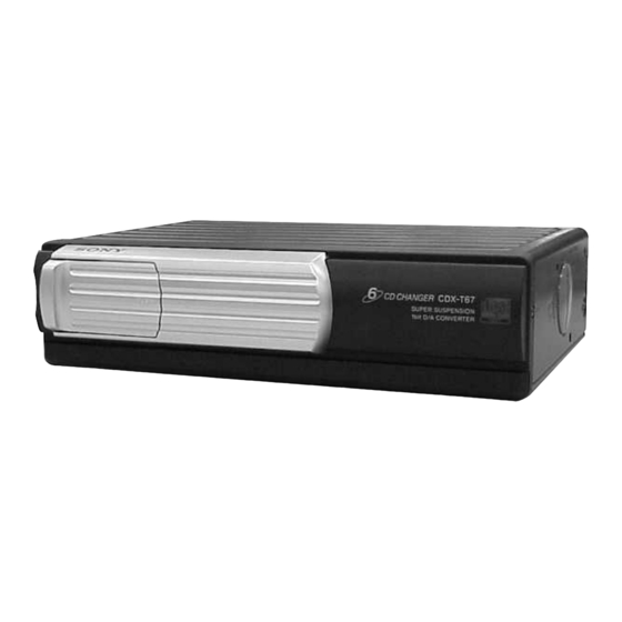
COMPACT DISC CHANGER
US Model
AEP Model
UK Model
E Model
NEW
MG-276A-159
KSS-720A
Inhaltsverzeichnis

Verwandte Anleitungen für Sony CDX-T67


Inhaltszusammenfassung für Sony CDX-T67
- Seite 1 CDX-T67 SERVICE MANUAL US Model Canadian Model Ver 1.1 2001.05 AEP Model UK Model E Model Model Name Using Similar Mechanism CD Drive Mechanism Type MG-276A-159 Optical Pick-up Name KSS-720A SPECIFICATIONS System Compact disc digital audio system Frequency response 10 – 20,000 Hz...
-
Seite 2: Servicing Notes
DE FONCTIONNEMENT. NE REMPLACER CES COM- which have the “CAUTION LABEL” attached, please be sure to POSANTS QUE PAR DES PIÈCES SONY DONT LES put a new CAUTION LABEL (3-223-913-11) to the chassis (U.S) NUMÉROS SONT DONNÉS DANS CE MANUEL OU sub assy. -
Seite 3: Inhaltsverzeichnis
CDX-T67 SECTION 1 This section is extracted from instruction manual. GENERAL TABLE OF CONTENTS Inserting a disc Insertion d un disque Einlegen von CDs Een disc inbrengen Inserimento di un disco Labeled surface up With the arrow side facing up... -
Seite 4: Installation
• Utilizzare solo le viti in dotazione. To the car audio (the master unit) compatible with the Sony Bus or the source selector • Pour garantir la sécurité de l’installation, utiliser beschädigt werden. Achten Sie auch darauf, daß die •... -
Seite 5: Disassembly
CDX-T67 SECTION 2 DISASSEMBLY • This set can be disassembled in the order shown below. 2-1. DISASSEMBLY FLOW Note 1: The process described in can be performed in any order. Note 2: Without completing the process described in , the next process can not be performed. -
Seite 6: Front Panel (S) Assy, Case (Upper S)
CDX-T67 Note: Follow the disassembly procedure in the numerical order given. 2-2. FRONT PANEL (S) ASSY, CASE (UPPER S) 3 screw (PTT2.6 × 6) 4 case (upper S) 5 lever (FLT. 838) 1 screw (PTT2.6 × 6) 3 screw (PTT2.6 × 6) 2 front panel (S) assy 5 lever (FLT. -
Seite 7: Jack Board
CDX-T67 2-4. JACK BOARD 2 screw (FP) 1 Remove ten solders of the cord (with connector). 3 jack board 4 ground point screw (PTT2.6 × 6) 5 cord (with connector) (BUS/RCA) 2-5. BELT (TS) 3 two screw (FP) 4 rack (UD) -
Seite 8: Main Board
CDX-T67 2-6. MAIN BOARD 3 three screws (FP) 2 Remove three solders of the slide variable resistor (RV301). 4 main board 1 main flexible board 2 Remove two solders (CN101) of the elevator motor lead wires (M104). 2-7. ESCUTCHEON (S), SLIDE VARIABLE RESISTOR (ELEVATOR HEIGHT SENSOR) (RV301) -
Seite 9: Md Motor Assy (Elevator) (M104)
CDX-T67 2-8. MD MOTOR ASSY (ELEVATOR) (M104) 1 screw (PTT2 × 3) 2 bracket (MDM) 3 MD motor assy (elevator) (M104) 2-9. LE MOTOR ASSY (CHUCKING) (M103) 3 screw (P1.7 × 2.2) 7 bracket (LEM) 2 tension spring (rack) 6 LE motor assy... -
Seite 10: Rf Board
CDX-T67 2-10. RF BOARD 3 two screws (PS2 × 4) 4 heat sink 1 main flexible board 5 screw (CN101) (PS2 × 4) 2 Remove two solders of the sled motor lead wires 6 RF board (M101). 1 OP flexible board... -
Seite 11: Optical Pick-Up (Kss-720A)
CDX-T67 2-12. OPTICAL PICK-UP (KSS-720A) 6 gear (SL2) 2 two screws 8 screw (P2 × 3) (P2 × 3) 5 washer 3 spring (sled front point) (DIA. 1.2) 9 detent spring (sled) 7 bearing (sled) assy 0 shaft (sled feed) assy... -
Seite 12: Lever (Chk.l) Assy, Lever (Chk.r) Assy
CDX-T67 2-14. LEVER (CHK.L) ASSY, LEVER (CHK.R) ASSY 3 Move the lever (CHK.L) assy fully in the direction of arrow A . 4 lever (CHK.L) assy 1 screw (P1.7 × 2.2) leaf spring (D retainer R) 2 joint (CHK) 3 Move the lever (CHK.R) assy fully in the direction of arrow A . -
Seite 13: Mechanical Adjustment
CDX-T67 SECTION 3 MECHANICAL ADJUSTMENT • Elevator Height (Address) Adjustment Adjustment Method: Note: This adjustments is necessary when the system controller (IC301), variable resistor (RV302), lever (CHK.L) assy, lever (CHK.R) assy, 1. Connect this set to the master unit (e.g. MDX-C7970/C7970R), or chassis (EV) assy was replaced for any repair. -
Seite 14: Electrical Check
CDX-T67 SECTION 4 ELECTRICAL CHECK Note: Focus Bias Check 1. This check is performed with the set placed horizontally. 2. Power supply voltage: DC14.4 V (more than 3 A). Connection: 3. Be sure to use the disc “YEDS-18” parts code: 3-702-101-01, but only –... - Seite 15 CDX-T67 Tracking Offset Check Connection: – RF Board (Component Side) – oscilloscope (DC range) – TP (TE) IC101 TP (VC) Procedure: 1. Connect the oscilloscope to TP (TE) and TP (VC) on the RF board. 2. Put the set into play mode by loading the disc (YEDS-18).
- Seite 16 CDX-T67 MEMO...
-
Seite 17: Diagrams
CDX-T67 SECTION 5 DIAGRAMS 5-1. BLOCK DIAGRAM – SERVO Section – FILTER RF AMP, 53 56 55 FOCUS/TRACKING ERROR AMP IC101 CN902 (1/2) DETECTOR AOUT2 AIN2 LOUT1 SERIAL RFAC GROUND- RFAC RFAC RF EQ RFAC ASYMMENTRY DIGITAL DIGITAL FILTER, SUMMING &... -
Seite 18: Block Diagram - Bus Control/Power Supply Section
ELVON 24 RESET SIGNAL RESET GENERATOR IC204 CN902 (2/2) IC901 REGULATOR µCOM B+ B. UP Q205, 206 BUS INTERFACE (FOR SONY BUS) IC201 DATA UNI SI DATA UNI SO UNI CK BUSON OUT BUSON BUSON BUSON OUT BUSON IN RESET... -
Seite 19: Note For Printed Wiring Boards And Schematic Diagrams
CDX-T67 5-3. NOTE FOR PRINTED WIRING BOARDS AND SCHEMATIC DIAGRAMS • Waveforms – RF Board – – MAIN Board – Note on Printed Wiring Board: Note on Schematic Diagram: • All capacitors are in µF unless otherwise noted. pF: µµF •... -
Seite 20: Printed Wiring Boards - Rf Board
CDX-T67 Ver 1.1 2001.05 5-4. PRINTED WIRING BOARDS – RF Board – RF BOARD (COMPONENT SIDE) RF BOARD (CONDUCTOR SIDE) M101 (SLED) (CHASSIS) OP FLEXIBLE BOARD OPTICAL PICK-UP BLOCK KSS-720A C119 R106 C114 MAIN (TE) BOARD CN202 (Page 22) MAIN... -
Seite 21: Schematic Diagram - Rf Board
CDX-T67 Ver 1.1 2001.05 5-5. SCHEMATIC DIAGRAM – RF Board – • • See page 19 for Waveforms. See page 27 for IC Block Diagrams. Q101 C110 2SB624T1-BV345 C111 R119 AUTOMATIC 6.3V POWER CONTROL R127 RF AMP, FOCUS/TRACKING C107 ERROR AMP... -
Seite 22: Main Board (Component Side)
5-6. PRINTED WIRING BOARDS – MAIN Board (Component Side) – CDX-T67 Ver 1.1 2001.05 • Semiconductor Location Ref. No. Location D201 D202 D203 D204 D207 D209 MAIN BOARD (COMPONENT SIDE) D210 D212 D213 IC201 IC203 B-10 IC204 IC301 IC302 IC401... -
Seite 23: Main Board (Conductor Side)
5-7. PRINTED WIRING BOARD – MAIN Board (Conductor Side) – CDX-T67 • Semiconductor Location Ref. No. Location MAIN BOARD (CONDUCTOR SIDE) IC202 (CHASSIS) EVEVATOR HEIGHT SENSOR MAGAZINE (CHASSIS) DETECT (CHASSIS) M104 (EVEVATOR) (11) 1-680-827-... -
Seite 24: Schematic Diagram - Main Board (1/2)
DATA DATA SWITCH RESET R201 B.UP X301 4MHz C302 B.UP (Page 26) 0.01 C301 B.UP 0.01 BUS INTERFACE JACK (FOR SONY BUS) FLEXIBLE BOARD C202 4700p Q205 C216 2SB1202FAST-TL 0.01 RAMA4 RAMIO2 Q206 R205 R301 2SC2712-YG RESET SIGNAL RAMA5 RESET... -
Seite 25: Schematic Diagram - Main Board (2/2)
CDX-T67 5-9. SCHEMATIC DIAGRAM – MAIN Board (2/2) – • • See page 19 for Waveforms. See page 27 for IC Block Diagram. C402 0.01 R503 R504 C503 C504 0.001 0.001 R306 R501 R502 C501 C502 R505 R506 150p 150p... -
Seite 26: Printed Wiring Boards - Jack Board
5-10. PRINTED WIRING BOARDS – JACK Board – 5-11. SCHEMATIC DIAGRAM – JACK Board – CN902 CN901 FB901 JACK BOARD FB902 AGND AGND FB903 (COMPONENT SIDE) BUSON BUSON (FOR SONY BUS) DATA DATA B.UP B.UP IC901 B.UP (Page 24) B.UP JACK FLEXIBLE BOARD (CHASSIS) - Seite 27 CDX-T67 • IC Block Diagrams – RF Board – IC101 CXA2581N-T4 RW/ROM DC OFST RFDCI – – RFDCO – RW/ROM VOFST APC AMP EQ ON/OFF RFAC EQ IN RW/ROM RFAC AC SUM SUMMING VOFST – – RW/ROM TE BAL RW/ROM –...
- Seite 28 CDX-T67 IC201 LA6576L-TE-L S-GND THERMAL SHUT DOWN CH2-4 INPUT MUTE2 MUTE VCC2 MUTE1 MUTE VLO– OUTPUT VIN4 CONTROL VLO+ VIN4– VO4+ VIN4+ LEVEL SHIFT VO4– VREF-IN VIN1/VREF VIN1 (VREF)-SW SWITCH VO3+ LEVEL VREF-OUT (CH1) SHIFT 5VREG VO3– – REG-OUT –...
- Seite 29 CDX-T67 IC302 LB1930M-TLM BUFFER OUT1 MOTOR CONTROL DRIVE CIRCUIT CIRCUIT OUT2 BUFFER S-GND P-GND IC401 CXD3017Q ERROR DIGITAL CORRECTOR ASYMMETRY DIGITAL CORRECTOR OPERATIONAL LRCK AMPLIFIER ANALOG SWITCH PCMD INTERFACE DEMODULATOR CONVERTER EMPH XVDD XTAI TIMING LOGIC CLOCK XTAO XTSL GENERATOR...
-
Seite 30: Ic Pin Function Description
Serial data reading clock signal output to the CXD3017Q (IC401) SENS Internal status signal (sense signal) input from the CXD3017Q (IC401) BUSON Bus on/off control signal input from the SONY bus interface (IC201) “H”: bus on Battery detection signal input “L”: battery on BUCHK... - Seite 31 70 to 74 Two-way data bus with the S-RAM Not used (open) RAMIO3 System reset signal input from the SONY bus interface (IC201) and reset signal generator (IC204) RESET “L”: reset For several hundreds msec. after the power supply rises, “L” is input, then it changes to “H”...
- Seite 32 CDX-T67 Pin No. Pin Name Description Chucking end detect switch (SW102) input terminal SAVE SW “L”: When completion of the disc chucking, loading or save operation Chucking end detect switch (SW102) input terminal LOAD SW “L”: When completion of the disc chucking, loading or save operation...
-
Seite 33: Exploded Views
CDX-T67 Ver 1.1 2001.05 SECTION 6 EXPLODED VIEWS NOTE: • -XX and -X mean standardized parts, so they • Items marked “*” are not stocked since they The components identified by mark 0 or dotted line with mark 0 are may have some difference from the original are seldom required for routine service. -
Seite 34: Mechanism Deck Section-1 (Mg-276A-159)
CDX-T67 6-2. MECHANISM DECK SECTION-1 (MG-276A-159) elevator assy section M104 not supplied Ref. No. Part No. Description Remark Ref. No. Part No. Description Remark A-3315-334-A CHASSIS ASSY, MAIN 3-227-133-01 BRACKET (MDM) 3-048-814-01 SCREW (M1.7X2.2) 3-227-150-01 SPRING, TENSION 3-227-131-01 BELT (TS) 3-701-440-21 WASHER, 3.5... -
Seite 35: Mechanism Deck Section-2 (Mg-276A-159)
CDX-T67 Ver 1.1 2001.05 6-3. MECHANISM DECK SECTION-2 (MG-276A-159) M101 not supplied not supplied M103 The components identified by Les composants identifiés par une mark 0 or dotted line with marque 0 sont critiques pour la mark 0 are critical for safety. -
Seite 36: Electrical Parts List
CDX-T67 Ver 1.1 2001.05 SECTION 7 JACK MAIN ELECTRICAL PARTS LIST NOTE: • Due to standardization, replacements in the • Items marked “*” are not stocked since they The components identified by mark 0 or dotted line with mark parts list may be different from the parts speci- are seldom required for routine service. - Seite 37 CDX-T67 Ver 1.1 2001.05 MAIN Ref. No. Part No. Description Remark Ref. No. Part No. Description Remark D213 8-719-071-34 DIODE RB521S-30-TE61 R508 1-216-813-11 METAL CHIP 1/16W < IC > R509 1-216-845-11 METAL CHIP 100K 1/16W R510 1-216-845-11 METAL CHIP 100K...
- Seite 38 CDX-T67 Ver 1.1 2001.05 Ref. No. Part No. Description Remark Ref. No. Part No. Description Remark < CONNECTOR > MISCELLANEOUS ************** CN101 1-793-820-21 CONNECTOR, FPC 22P CN102 1-815-016-21 CONNECTOR, FFC/FPC (ZIF) 16P 1-757-747-11 CORD (WITH CONNECTOR) (BUS/RCA) 1-680-823-11 JACK FLEXIBLE BOARD <...
-
Seite 39: Parts For Installation And Connections
CDX-T67 Ref. No. Part No. Description Remark Ref. No. Part No. Description Remark PARTS FOR INSTALLATION AND CONNECTIONS ************************************** 3-225-809-01 BRACKET (S) * 502 X-3369-824-1 SCREW ASSY 1-590-519-21 CORD (WITH CONNECTOR) (BUS CABLE 5m) 1-590-874-11 CORD, CONNECTION (RCA PIN CORD 5m) +PSW4 ×... -
Seite 40: Revision History
CDX-T67 REVISION HISTORY Clicking the version allows you to jump to the revised page. Also, clicking the version at the upper right on the revised page allows you to jump to the next revised page. Ver. Date Description of Revision 2001.05...