System Sensor SC-6 Installations- Und Wartungsanleitung
Überwachtes sechs-relais-steuermodul
Inhaltsverzeichnis
Verfügbare Sprachen
Verfügbare Sprachen
INSTALLATION AND MAINTENANCE INSTRUCTIONS
SC-6
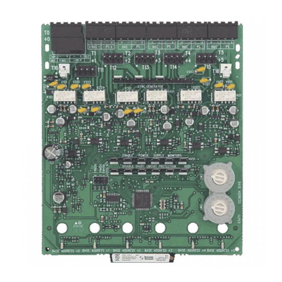
Six Supervised Control Module
SPECIFICATIONS
Normal Operating Voltage:
Stand-By Current:
Alarm Current:
Temperature Range:
Humidity:
Dimensions:
Accessories:
Wire Gauge:
Maximum Monitored Output Circuit
Wiring Resistance:
Table 1:
CURRENT RATING
3A
2A
1A
.5A
BEFORE INSTALLING
This information is included as a quick reference installation
guide. Refer to the appropriate control panel installation manual
for detailed system information. If the modules will be installed
in an existing operational system, inform the operator and local
authority that the system will be temporarily out of service.
Disconnect the power to the control panel before installing the
modules. This system contains static sensitive components.
Always ground yourself with a proper wrist strap before handling
any circuits so that static charges are removed from the body. The
housing cabinet should be metallic and suitably grounded.
NOTICE: This manual should be left with the owner/user
of this equipment.
GENERAL DESCRIPTION
The SC-6 Six Supervised Control Module is intended for use in an
intelligent alarm system. Each module is intended for switching
applications involving DC which require wiring supervision. A
common SLC input is used for all modules. Each module has its
own address. A pair of rotary code switches is used to set the
address of the first module from 01 to 94. The remaining mod-
ules are automatically assigned to the next five higher addresses.
Provisions are included for disabling a maximum of three unused
modules to release the addresses to be used elsewhere. Each
module also has panel controlled green LED indicators. The panel
can cause the LEDs to blink, latch on, or latch off.
Each module has terminals for connection to an external supply
circuit for powering devices on its Monitored Output Circuit.
Each supply must be power limited and its voltage/current limits
must be at or below those specified in Table 1.
There is a short circuit protection monitor for each module. This
is provided to protect the external power supply against short
circuit conditions on the Monitored Output Circuit.
D500-68-00
15-32VDC
2.25 mA
35 mA (assumes all six relays have been switched once and all six LEDs solid on)
-10°C to 55°C
10 to 93% Non condensing
17.3cm H x 14.7cm W x 3.2cm D
Suitably grounded metallic cabinet
0.9mm 2 - 3.25mm 2
40 Ohms
MAXIMUM VOLTAGE
30VDC
30VDC
30VDC
30VDC
Included:
(7) 1 x 4 Terminal
(2) Screws
(1) Long Power
Supply Jumper
Shipped on Board:
(1) Small shunt
(6) Large shunts on Enable Power Supply Monitors
(6) Large shunts on Disable Short Circuit Protection
(3) Large shunts on Sync Generator
NOTE: Three shunts on Sync Generator MUST NOT be removed.
COMPATIBILITY REQUIREMENTS
To ensure proper operation, this module shall be connected to a
listed compatible control panel.
The SC-6 Module shall be mounted in a suitably grounded
Metallic Cabinet for EMC compliance.
1
LOAD DESCRIPTION
Resistive
Resistive
Inductive (L/R=2ms)
Inductive (L/R=5ms)
(2) 32mm Stand offs
Blocks
(5) Short Power
Supply Jumpers
(2) EOL Relay
Pittway Technologica S.p.A
Via Caboto 19/3
34147 Trieste, Italy
APPLICATION
Steady
Pulsing
Pulsing
Pulsing
(15) Large
Shunts
(2) Small Shunts
(6) 47k Ohm
End of Line
Resistors
Connector Assembly
I56-2253-01
Inhaltsverzeichnis

Verwandte Anleitungen für System Sensor SC-6


Inhaltszusammenfassung für System Sensor SC-6
-
Seite 13: Spezifikation
HINWEIS: Diese Anleitung sollte dem Betreiber ausgehändigt für Spannungsversorgung Steckbrücken und der Anlagendokumentation beigefügt werden. ALLGEMEINES Das SC-6 Relais-Steuermodul wird in intelligenten (1) Lange Steckverbinder (6) 47k Ohm Verbinder für Gefahrenmeldeanlagen eingesetzt. Jedes Modul ist für das für Spannungsversorgung Abschlusswiderstand überwachte Schalten von Wechsel- oder Gleichspannung sowie... -
Seite 14: Verdrahtungshinweise
Für den ordnungsgemäßen Betrieb muss das Modul an eine ZUKÜNFTIGE FUNKTION geeignete und kompatible Brandmelderzentrale angeschlossen werden. EINSCHALTUNG SPANNUNGSÜBERWACHUNG Das SC-6-Modul sollte für die Erfüllung der EMV-Richtlinie in ABSCHALTUNG KURZSCHLUSSÜBERWACHUNG einem geeigneten, geerdeten Metallgehäuse montiert werden VERDRAHTUNG HINWEIS: Die Verdrahtung muss gemäß den regionalen Auflagen, Richtlinien und Anforderungen ausgeführt werden. -
Seite 15: Jumper Stellung
T10 pin 2 +4 and +5 Die Versorgungsspannung für mehrere Module in einem Alle externen Versorgungsspannungen (außerhalb des SC-6 Gehäuse kann mit einem Kabel weiterverbunden werden Montagegehäuses) sollten an die Anschlüsse T0-T5 angeschlos- ( typische Darstellung in Abbildung 4 ). Um mehrere Platinen sen werden, die auch für den Anschluss der Ausgangsleitungen... - Seite 16 Versorgung der überwachten Steuerausgänge +0 and +1 (auf Platine 1) sowie +3, +4, and +5 (auf Platine 2) genutzt. Die Abbildungen 3 zeigen die typische Verdrahtung der Ausgangskreise. Vergewissern Sie sich dass der Stecker des Spannungskabel, wie in der Darstellung A-A gezeigt, fest in den Halteclip von T10 oder T16 einrastet. D500-68-00 I56-2253-01 © 2003 System Sensor...