Clorius Controls VB series Handbuch
Für regelungszwecke

Verwandte Anleitungen für Clorius Controls VB series

Inhaltszusammenfassung für Clorius Controls VB series
- Seite 1 99.48.00-H Electric Valve Actuator type VB, VBA Instructions Siłownik typ VB, VBA Instrukcja...
- Seite 2 Warning! 1) This electric actuator is designed for regulation purposes, and therefore it must not be used as a safety actuator. 2) If the electric actuator is put into manual operation, the automated function loses control of the temperature. 3) Prior to start using the electric actuator its travel has to be adjusted to the lifting height of the valve.
- Seite 3 Advarsel! 1) Denne aktuatoren er konstruert til reguleringsformål og må derfor ikke brukes som sikkerhetsaktuator. 2) Dersom aktuatoren settes i manuell håndbetjening, mister automatikken kontrollen med temperaturen. 3) Før aktuatoren tas i bruk, må aktuatorens slaglengde tilpasses ventilens løftehøyde. 4) Følgende gjelder bare type VBA: ved innkobling av driftsspenning eller etter aktivering av girutløserknappen, foretar VBA-aktuatoren en automatisk funksjonstest.
- Seite 4 Prior to installation Check that the type of actuator and the voltage match the valve actuator ordered and that the travel of the valve actuator is sufficient for the valve in hand. Vor der Montage Überprüfen, daß der Antriebtyp und die Betriebsspannung dem bestellten Antrieb entsprechen sowie daß...
- Seite 5 Type Designation Rated travel No. of auxillary Power Control signal switches 0 - 10 mm VB - 90 - 230 V 230 V 3 point VB - 92 - 230 V VB - 90 - 24 V 24 V 3 point AC/DC VB - 92 - 24 V VBA - 90 - 24 V...
- Seite 6 Installation Assemble actuator and valve as shown in the figure. The fitting angle is optional. However, if the temperature of the medium exceeds 170ºC the actuator shall be fitted below the valve and a cooling piece of the type KS-4 or KS-6 is to be fitted. Montage Antrieb und Ventil werden wie in der Abbildung angezeigt zusammengebaut.
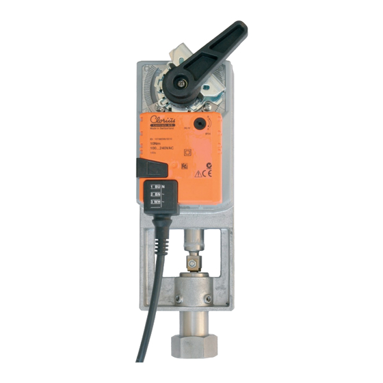
- Seite 8 Setting of travel The travel of the electric actuator has been preset by the factory at 10 mm. Dependent on the type of valve the travel has to be adjusted to the lifting height of the valve. A) Put the actuator in position “1” by means of the gear release button (1) and the handle (2). B) Adjust the screw (3) until the actuator stops 1–3 mm before it reaches the end stop in position “1”.Tighten the cup point screw (5) in such a manner that the adjustment of the end stop is fixed in position „1“.
- Seite 9 Indstilling af slaglængde Aktuatoren er fra fabrikken indstillet til slaglængde 10 mm. Denne slaglængde skal, afhængig af den anvendte ventiltype, tilpasses ventilens løftehøjde. A) Ved hjælp af gearudløserknappen (1) og håndtag (2) bringes motor i position ”1“ B) Juster den firkantede skrue (3) så motor stopper 1–3 mm før der er kontakt med endestoppet i position ”1“.
- Seite 10 Electrical connections The low-voltage regulations and local legislation are always to be complied with when installing the electric actuator. Direction of rotation: The electric actuator has a micro switch allowing reversing of the direction of rotation without altering the electric connections. Elektrische Anschlüsse Bei elektrischer Installation sind die jeweiligen Niederspannungsrichtlinien und die nationalen gesetzlichen Vorschriften immer zu einzuhalten: Der Antrieb ist mit einem Mikroschalter...
- Seite 11 24 V AC/DC 24 V AC / 24 V DC Controller Analogue Analogue 4-20 mA – 0 24 V 500 Ω ∗ + 0…10 V DC 2...10 V Input Socket 4-20 mA + 2…10 V Output VBA-_ _-24 VBA-__-24 24 V AC / 24 V DC 100 - 240 V AC Open-close control Open-close control...
- Seite 12 Maintenance The electric actuator is greased for life and therefore requires no maintenance. Wartung Der Antrieb ist für die technische Lebensdauer geschmiert und erfordert deshalb keine Wartung. Mantenimiento El actuador de válvula se ha lubricado en fábrica y no requiere ulterior mantenimiento en su vida útil.
- Seite 13 Auxiliary contacts 1 set of auxiliary contacts are available as optional equipment. The set is available with 2 making/breaking contacts. The contact function is freely adjustable across the full range. Current: 1 mA ...3 (0.5) A, 250 V AC. Hilfskontakte Als zusätzliche Ausrüstung kann 1 Satz Hilfskontakte mitgeliefert werden.
- Seite 14 Styki pomocnicze Auxiliary contacts S1 S2 S3 S4 S5 S6 < x < x > x > x x = 0...100%...
- Seite 16 Clorius Controls A/S Tempovej 27 · DK-2750 Ballerup · Denmark Tel.: +45 77 32 31 30 · Fax: +45 77 32 31 31 E-mail: mail@cloriuscontrols.com Web: www.cloriuscontrols.com...