Herunterladen Inhalt Inhalt Diese Seite drucken
bürkert 0258 Bedienungsanleitung

bürkert 0258 Bedienungsanleitung

Modulares 2- und 3-wege-motorregelventil
Inhaltsverzeichnis

Werbung

Verfügbare Sprachen

Verfügbare Sprachen

Operating Instructions
Bedienungsanleitung
Instructions de Service
Type 0258
Modular 2 and 3-way motor control valve
Modulares 2- und 3-Wege-Motorregelventil
Vanne de régulation motorisée
modulaire à 2 et 3 voies

Werbung

Inhaltsverzeichnis
loading

Inhaltszusammenfassung für bürkert 0258

  • Seite 1 Operating Instructions Bedienungsanleitung Instructions de Service Type 0258 Modular 2 and 3-way motor control valve Modulares 2- und 3-Wege-Motorregelventil Vanne de régulation motorisée modulaire à 2 et 3 voies...
  • Seite 2 We reserve the right to make technical changes without notice. Technische Änderungen vorbehalten. Sous resérve de modification techniques. © 2004 Bürkert Werke GmbH & Co. KG Operating Instructions 0601/00_EU-EN_00804858...
  • Seite 3: Inhaltsverzeichnis

    General data ................... 12 Mechanical data ..................12 Electrical data ..................13 Electrical connections ................14 Plug configuration Mod ................14 Plug configuration LC ..................14 OPERATING AND DISPLAY ELEMENTS ..........15 Emergency manual override ..............15 0258 - 1...
  • Seite 4 Dimensional drawings for 3-way check valve block with shut-off valve ................. 18 MAINTENANCE ................... 19 Safety notes .................... 19 Service ..................... 19 Service intervals ..................19 Correction of faults ................19 TRANSPORT AND STORAGE ..............20 DISPOSAL ....................20 2 - 0258...
  • Seite 5: General Notes

    • Only use the device in its original configuration! • On non-observance of this note and unauthorized interference with the device, we will refuse all liability and the guarantee on device and accessories will become void. 0258 - 3...
  • Seite 6: Application Guidelines

    The configuration that is required for your special application will be drawn up by our Field Service employees. Only use the Type 0258 modular 2 and 3-way motor control valve for the applications agreed with the Bürkert company.
  • Seite 7: Approval

    023187 You can obtain an excerpt from the type approval from the address below Bürkert Werke GmbH & Co KG Zulassungsbeauftragter Christian Bürkert Str.13-17 74653 Ingelfingen 0258 - 5...
  • Seite 8: System Description

    SYSTEM DESCRIPTION Application area The modular 2 and 3-way motorized regulating valve of Type 0258 is preferably used as a control element for hot water or coolant circuits in buses, goods vehicles, floating and rail vehicles, as well as in machine tool construction.
  • Seite 9: Control Functions Of The Valves

    Flow: Kv value water [m³/h], measurement at +20 °C, 1 bar pressure at valve inlet port and free outlet port. only Mod drive type in relation to the total stroke of the potentiometer = 100 % Pressure quoted in [bar]: over-pressure with regard to atmospheric pressure 0258 - 7...
  • Seite 10: Marking

    The motorised regulating valve is marked with two labels. The rating label for the complete device (valve block) is located on the lower left side. The upper line gives the device specification key "SYST-0258", while the lower line gives the identity number and the encoded date of manufacture.
  • Seite 11: Basic Module

    Note the direction of flow. As an option, the filter module can be fitted with a magnetic insert. Block symbol 2-way flow valve Description The 2-way flow valve is continuously operated. The direction of flow: A, P Block symbol 0258 - 9...
  • Seite 12: 3-Way Mixing Or Distribution Valve

    Manual lever at the left stop: closed B open Note the direction of flow. Block symbol Shut-off valve Description Hand lever The shut-off valve is operated manually. The direction of flow is freely selectable. Block symbol Mounting angle 10 - 0258...
  • Seite 13: Technical Data

    ( m m ) ( m m ) ( m m ) ( m m ) ( m m ) ( m m ) ( m m ) ( m m ) ( m m ) TU22 TU28 TU35 0258 - 11...
  • Seite 14: General Data

    Mod. nom./max.: 1.2 Nm / 2.1 Nm Block assembly with mounting plates and adapters Fixation with fixing angles and tie rods Installation position any, preferably with drive above Basic module 2- and 3-way valves Check valve Filter module, lockable Hand shut-off valve 12 - 0258...
  • Seite 15: Electrical Data

    Higher currents considerably reduce the service life! Higher temperatures limit the max. power loss of the potentiometers. min. pulse length (the min. pulse length increases at no-load/ at pressure/load): for LC: approx. 100 ms / for Mod.: approx. 100 ms 0258 - 13...
  • Seite 16: Electrical Connections

    Pin 4 Pin 4 Pin 4 Pin 6 Pin 6 Pin 6 configuration configuration Pin 4 Pin 4 Pin 6 Pin 6 left running minus plus right running plus minus P1 = 5.0 kΩ 14 - 0258...
  • Seite 17: Operating And Display Elements

    Turn the emergency manual override the the right: outlet port A closes and outlet port B opens at the same time. Turn the emergency manual override to the left, outlet port B closes and outlet port A opens. The transition is flowing. 0258 - 15...
  • Seite 18: Putting Into Operation

    Single blocks are secured with tie rods or angle brackets, and dual and quad blocks with angle brackets. OPERATION AND FUNCTION Safety notes ATTENTION! Observe the following during operation • compliance with the general technical rules! • the valid accident prevention and safety regulations for electrical device. 16 - 0258...
  • Seite 19: Accessory

    Description Description Order no. Order no. Order no. Order no. Order no. Filter shut-off module 191 327 Filter magnet shut-off module 198 066 Dimensional drawings for modular filter type 250, solo DN 25 DN 25 Ö7 Ö7 0258 - 17...
  • Seite 20: 3-Way Check Valve Block With Shut-Off Valve

    Order no. Description Description Description Order no. Order no. Order no. Check valve block with 192 218 shut-off cock Dimensional drawings for 3-way check valve block with shut-off valve TU 35 manual lever TU 28 Open Closed 18 - 0258...
  • Seite 21: Maintenance

    If you detect faults that have an effect on the functionality of the motorised control valve, these must be corrected immediately: • Place the device out of operation, and switch it free of voltage! • Correct the fault. • Put the device back into operation. 0258 - 19...
  • Seite 22: Transport And Storage

    TRANSPORT AND STORAGE Transport and storage are only permitted in the original packaging. DISPOSAL NOTE Observe the national regulations for the disposal of waste in the respective country of use. 20 - 0258...
  • Seite 23 4fach Block ...................... 31 Leitungsanschlüsse (Schlauch) ..............31 Allgemeine Daten ................... 32 Mechanische Daten ................32 Elektrische Daten ................... 33 Elektrische Anschlüsse ................. 34 Steckerbelegung Mod ................... 34 Steckerbelegung LC ..................34 BEDIEN- UND ANZEIGEELEMENTE ............. 35 Handnotbetätigung ................35 0258 - 21...
  • Seite 24 3fach Rückschlagventilblock mit Absperrventil ......38 Maßzeichnung 3fach Rückschlagventilblock mit Absperrventil ..................38 INSTANDHALTUNG ..................39 Sicherheitshinweise ................39 Wartung ....................39 Wartungsintervalle ................. 39 Beseitigung von Fehlern ............... 39 TRANSPORT UND LAGERUNG ............40 ENTSORGUNG ..................40 22 - 0258...
  • Seite 25: Allgemeine Hinweise

    Treffen Sie geeignete Maßnahmen, um unbeabsichtigtes Betätigen oder unzulässige Beeinträchtigung auszuschließen! • Verwenden Sie das Gerät nur in seiner Originalkonfiguration! • Bei Nichtbeachtung dieser Hinweise und unzulässigen Eingriffen in das Gerät entfällt jegliche Haftung unsererseits, ebenso erlischt die Garantie auf Geräte und Zubehörteile! 0258 - 23...
  • Seite 26: Bestimmungsgemäßer Gebrauch

    Die für Ihren speziellen Anwendungsfall erforderliche Konfigurati- on wird von unseren Mitarbeitern im Außendienst zusammengestellt. Verwen- den Sie das modulare 2- und 3-Wege-Motorregelventil vom Typ 0258 nur für diesen mit der Fa. Bürkert vereinbarten Anwendungsfall. Eine anderweitige Verwendung muss mit dem Kundenservice der Fa. Bürkert abgesprochen werden.
  • Seite 27: Zulassung

    Typgenehmigungsnummer e1*72/245*95/54*3187*00 genehmigt und werden mit dem gezeigten Typgenehmigungzeichen in den Verkehr gebracht. 023187 Einen Auszug der Typgenehmigung erhalten Sie unter der unten stehenden Adresse. Bürkert Werke GmbH & Co KG Zulassungsbeauftragter Christian Bürkert Str.13-17 74653 Ingelfingen 0258 - 25...
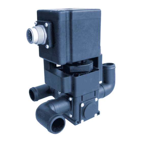
  • Seite 28: Systembeschreibung

    Handnotbetätigung (optische Stellungsanzeige) Ventilmodul Das Motorregelventil Typ 0258 ist modular aufgebaut und wird einzeln oder zu Blöcken angereiht montiert. In einem Block sind bis zu 4 Ventile kombinierbar. Es kann wahlweise als 2- oder 3-Wege-Ventil eingesetzt werden. Es enthält keramische Dichtelemente, das Ventilgehäuse besteht aus Kunststoff.
  • Seite 29: Wirkungsweisen Des Ventils

    Kv-Sollwert = 3 m Potentiometer Durchfluss: Kv-Wert Wasser [m³/h], Messung bei +20 °C, 1 bar Druck am Ventileingang und freiem Ausgang. nur Antriebsart Mod relativiert auf den Gesamthub des Potentiometers = 100 % Druckangabe in [bar]: Überdruck zum Atmosphärendruck 0258 - 27...
  • Seite 30: Kennzeichnung

    Das Typenschild für das Komplettgerät (Ventilblock) befindet sich unten auf der linken Seite. Es bezeichnet in der oberen Zeile den Geräteschlüssel "SYST-0258", in der unteren Zeile die Identnummer sowie das verschlüsselte Baudatum. Jeder Antrieb verfügt außerdem über ein eigenes Typenschild mit folgendem Inhalt: •...
  • Seite 31: Grundmodule

    Alle Grundmodule können Sie einzeln oder im Block einsetzen. Filtermodul Beschreibung Handhebel Das Filtermodul kann von Hand abge- sperrt werden. Beachten Sie die Durchflussrichtung. Optional kann das Filtermodul mit einem Magneteinsatz ausgerüstet sein. Blocksymbol 2-Wege-Durchlassventil Beschreibung Das 2-Wege-Durchlassventil ist stetigwirkend. Die Durchflussrichtung: A, P Blocksymbol 0258 - 29...
  • Seite 32: 3-Wege-Misch- Oder Verteilerventil

    Beschreibung Das Rückschlagventil hat Sammelfunktion. Handbetätigung ist möglich. Handhebel in Linksanschlag: A geschlossen B offen Beachten Sie die Durchflussrichtung. Blocksymbol Absperrventil Beschreibung Handhebel Das Absperrventil wird von Hand betä- tigt. Die Durchflussrichtung ist belie- big. Blocksymbol Befestigungswinkel 30 - 0258...
  • Seite 33: Technische Daten

    ( m m ) ( m m ) ( m m ) ( m m ) ( m m ) ( m m ) ( m m ) ( m m ) ( m m ) TU22 TU28 TU35 0258 - 31...
  • Seite 34: Allgemeine Daten

    LC nom./max.: 0,35 Nm / 0,7 Nm Mod. nom./max.: 1,2 Nm / 2,1 Nm Blockaufbau mit Klemmblechen und Zwischenadaptern Befestigung mit Haltewinkeln und Zugstangen Einbaulage beliebig, vorzugsweise Antrieb nach oben Grundmodule 2- und 3-Wege-Ventile Rückschlagventil Filtermodul, absperrbar Hand-Absperrventil 32 - 0258...
  • Seite 35: Elektrische Daten

    Höhere Ströme schränken die Lebensdauer stark ein! Höhere Temperaturen schränken die max. Verlustleistung des Potentiometers ein. min. Pulsdauer (im Leerlauf / bei Druck/Last erhöht sich die min. Pulsdauer): bei LC: ca. 100 ms / bei Mod.: ca. 100 ms 0258 - 33...
  • Seite 36: Elektrische Anschlüsse

    Steckerbelegung LC Polbelegung Polbelegung Pin 4 Pin 4 Pin 6 Pin 6 Polbelegung Polbelegung Polbelegung Pin 4 Pin 4 Pin 4 Pin 6 Pin 6 Pin 6 Linkslauf minus plus Rechtslauf plus minus P1 = 5,0 kΩ 34 - 0258...
  • Seite 37: Bedien- Und Anzeigeelemente

    Die optische Stellungsanzeige resultiert aus der Lage der Handnot- betätigung. Drehen Sie die Handnotbetätigung nach rechts, schließt sich Ausgang A und Ausgang B wird gleichzeitig geöffnet. Drehen Sie die Handnotbetätigung nach links, schließt sich Ausgang B und Ausgang A wird geöffnet. Der Übergang ist fließend. 0258 - 35...
  • Seite 38: Inbetriebnahme

    Einfach-Blöcke werden durch Zugstangen oder Winkel, 2fach- bis 4fach- Blöcke durch Winkel befestigt. BEDIENUNG UND FUNKTION Sicherheitshinweise ACHTUNG! Beachten Sie bei der Bedienung und im Betrieb • die Einhaltung der allgemeinen Regeln der Technik! • die geltenden Unfallverhütungs- und Sicherheits- bestimmungen für elektrische Geräte. 36 - 0258...
  • Seite 39: Zubehör

    ZUBEHÖR Modularer Filter Typ 250, solo Bezeichnung Bezeichnung Bezeichnung Bezeichnung Bezeichnung Bestell-Nr. Bestell-Nr. Bestell-Nr. Bestell-Nr. Bestell-Nr. Filter-Absperrmodul 191 327 Filter Magnet Absperrmodul 198 066 Maßzeichnungen Modularer Filter Typ 250, solo DN 25 DN 25 Ö7 Ö7 0258 - 37...
  • Seite 40: 3Fach Rückschlagventilblock Mit Absperrventil

    3fach Rückschlagventilblock mit Absperrventil Bezeichnung Bezeichnung Bestell-Nr. Bestell-Nr. Bezeichnung Bezeichnung Bezeichnung Bestell-Nr. Bestell-Nr. Bestell-Nr. Rückschlagblock mit Ab- 192 218 sperrhahn Maßzeichnung 3fach Rückschlagventilblock mit Absperrventil TU 35 Handhebel TU 28 38 - 0258...
  • Seite 41: Instandhaltung

    Haben Sie Fehler festgestellt, die sich auf die Funktionsfähigkeit des Motor- regelventils auswirken, müssen diese sofort beseitigt werden: • Setzen Sie das Gerät außer Betrieb, schalten Sie es spannungsfrei! • Beseitigen Sie den Fehler. • Nehmen Sie das Gerät wieder in Betrieb. 0258 - 39...
  • Seite 42: Transport Und Lagerung

    TRANSPORT UND LAGERUNG Transport und Lagerung sind nur in Originalverpackung gestattet. ENTSORGUNG HINWEIS Beachten Sie die nationalen Vorschriften zur Abfallentsor- gung im jeweiligen Einsatzland. 40 - 0258...
  • Seite 43 Caractéristiques mécaniques ............. 52 Caractéristiques électriques ............... 53 Branchements électriques ..............54 Affectation des connecteurs Mod .............. 54 Affectation des connecteurs LC ..............54 ORGANES DE COMMANDE ET D'AFFICHAGE ....... 55 Commande de secours manuelle ............55 0258 - 41...
  • Seite 44 Dessin dimensionnel du bloc de 3 clapets antiretour avec robinet d'arrêt ................58 MAINTENANCE ................... 59 Consignes de sécurité ................59 Entretien ....................59 Intervalle d'éntretien ................59 Elimination des défauts ................ 59 TRANSPORT ET STOCKAGE ..............60 MISE AU REBUT ..................60 42 - 0258...
  • Seite 45: Indications Generales

    N'utiliser l'appareil que dans sa configuration originale! • Nous déclinons toute responsabilité en cas d'inobservation des ces recommandations et d'intervention non autorisée à l'intérieur de l'appareil. Il en résulterait par ailleurs l'extinction de la garantie sur l'appareil et les accessoires! 0258 - 43...
  • Seite 46: Utilisation Conforme Aux Instructions

    La configuration nécessaire à votre application spéciale sera assemblée par nos collaborateurs du service de visite à la clientèle. Utiliser uniquement la vanne de régulation motorisée modulaire à 2 et 3 voies du type 0258 pour le cas d'application convenu avec la maison Bürkert. Une autre emploi doit être convenu avec le service après-vente de la maison Bürkert.
  • Seite 47: Homologation

    (Kraftfahrtbundesamt) sous le numéro e1*72/245*95/54*3187*00 et seront mis en circulation avec la marque d'homologation indiquée. 023187 Vous recevrez un extrait de l'homologation à l'adresse ci-dessous: Bürkert Werke GmbH & Co KG Zulassungsbeauftragter Christian Bürkert Str.13-17 74653 Ingelfingen 0258 - 45...
  • Seite 48: Description Du Systeme

    DESCRIPTION DU SYSTEME Mise en oeuvre La vanne modulaire de régulation motorisée de type 0258 est mise en oeuvre de préférence comme composant de réglage pour circuits d'eau chaude ou de réfrigérant dans des omnibus, véhicules utilitaires, flottants et sur rails de même que dans la construction de machines-outils.
  • Seite 49: Mode D'action De La Vanne

    Débit valeur Kv eau [m³/h], measure à +20 °C, 1 bars pression à l'entrée de la vanne et sortie libre uniquement entraînement Mod référencé à la course totale du potentiomètre = 100 % Indication de pression en [bar]: surpression par rapport à la pression atmosphérique 0258 - 47...
  • Seite 50: Marquage

    La plaque signalétique pour l'appareil complet (bloc de vannes) se trouve en bas du côté gauche. Elle désigne sur la ligne suérieure la clé de l'appareil "SYST-0258", sur la ligne inférieure le numéro d'identification de même que la date de construction codée.
  • Seite 51: Modules De Base

    Le module filtrant peut être équipe en option d'un insert magnétique. Symbol fonctionnel Vanne d'admission à 2 voies Description La vanne d'admission à 2 voies est à action continue. Le sens du débit: A, P Symbol fonctionnel 0258 - 49...
  • Seite 52: Vanne De Mélange Ou De Répartition À 3 Voies

    Manette dans butée de gauche: fermé B ouvert Faire attention au sens du débit. Symbole fonctionnel Vanne d'arrêt Description Manette La vanne d'arrêt est manœuvrée à la main. Le sens de débit est quelconque. Symbole fonctionnel Equerre de fixation 50 - 0258...
  • Seite 53: Caracteristiques Techniques

    ( m m ) ( m m ) ( m m ) ( m m ) ( m m ) ( m m ) ( m m ) ( m m ) ( m m ) TU22 TU28 TU35 0258 - 51...
  • Seite 54: Caractéristiques Générales

    équerres de soutien et barres de traction Position de montage quelconque, de préférence avec l'entraînement dirigé vers le haut Modules de base Vannes à 2 et 3 voies Clapet antiretour Module filtrant, pouvant être bloqué Vanne d'arrêt manuelle 52 - 0258...
  • Seite 55: Caractéristiques Électriques

    Des courants plus élevés limitent la longévité! Des températures plus élevées limitent la puissance dissipée max. du potentiométre. Durée d'impulsion min. (à vide / sous pression/charge la durée dìmpulsion min. augmente): avec LC: env. 100 ms / avec Mod.: env. 100 ms 0258 - 53...
  • Seite 56: Branchements Électriques

    Broche 4 Broche 4 Broche 4 Broche 4 Broche 4 Broche6 Broche6 Broche6 Broche6 Broche6 Rotation à gauche minus plus Rotation à droite plus minus P1 = 5,0 kΩ 54 - 0258...
  • Seite 57: Organes De Commande Et D'affichage

    Tournez la commande de secours à droite, la sortie A se ferme et la sortie B s'ouvre en même temps. Tournez la commande de secours manuelle à gauche, la sortie B se ferme et la sortie A s'ouvre. La transition est coulissante. 0258 - 55...
  • Seite 58: Mise En Service

    Consignes de sécurité ATTENTION! Veiller lors de la commande et en service • au respect des règles générales de la technique! • aux prescriptions en vigueur de prévention des accidents et de sécurité concernant les appareils électriques. 56 - 0258...
  • Seite 59: Accessoires

    Désignation Désignation N° de commande N° de commande N° de commande Module d'arrêt pour filtre 191 327 Filtre aimant module d'arrêt 198 066 Dessins dimensionnels du filtre modulaire type 250, solo DN 25 DN 25 Ö7 Ö7 0258 - 57...
  • Seite 60: Bloc De 3 Clapets Antiretour Avec Robinet D'arrêt

    N° de commande N° de commande N° de commande N° de commande N° de commande Bloc antiretour avec 192 218 robinet d'arrêt Dessin dimensionnel du bloc de 3 clapets antiretour avec robinet d'arrêt TU 35 Handhebel TU 28 58 - 0258...
  • Seite 61: Maintenance

    Si vous avez constanté des défauts ayant une influence sur la fonctionnalité de la vanne de régulation motorisée, ils doivent être immédiatement éliminés: • Mettre l'appareil hors service et hors tension! • Remédier au défaut. • Remettre l'appareil en service. 0258 - 59...
  • Seite 62: Transport Et Stockage

    TRANSPORT ET STOCKAGE Le transport et le stockage ne sont autorisés que dans l'emballage original. MISE AU REBUT REMARQUE Tenir compte des prescriptions nationales du pays d'emploi pour la mise au rebut. 60 - 0258...
  • Seite 63 NOTES 0258 - 61...
  • Seite 64 62 - 0258...
  • Seite 66 Int.(+33 388)57 2008, Nat. (0388)57 2008 Fax: Int.(+90232)459 7694,Nat.(0232)459 7694 E-mail: burkert.france@buerkert.com E-mail: burkert@superonline.com BC-I Italy, Italien Burkert Contromatic Italiana S.p.A. BC-UK United Kingdom, Centro Direzionale „Colombirolo“ Vereinigtes Königreich Via Roma, 74 Burkert Contromatic Limited I-20060 Cassina De’ Pecchi (Mi) Brimscombe Port Business Park Phone: Int.(+39 02)959 071, Nat.(02)959 071...
  • Seite 67 Addresses of BC offices/Adressliste BC Länder APAC Suzhou BC-AUS Australia, Australien Burkert Contromatic (Shanghai), Co., Ltd. BURKERT CONTROMATIC AUSTRALIA PTY, LTD. Room 5, #06-06 2 Welder Road Block A, No. 5 Xinghan Street Seven Hills, NSW 2147 SIP Suzhou P. R. China, 215021 Australia Phone:Int.(86512)67611916,Nat.(512)67611916...
  • Seite 68 Int.(+63 2)776 43 82, Nat.(02)776 43 82 Fax: Int.(+886 2)2653 7968, Nat.(02)2653 7968 E-mail: info.rp@burkert.com E-mail: info.rc@burkert.com BC-SIN Singapore, Singapur BURKERT CONTROMATIC SINGAPORE PTE. LTD. 51 Ubi Avenue 1, #03-14 Paya Ubi Industrial Park Singapore 408933 SINGAPORE Phone: Int.(+65)6844 2233, Nat.6844 2233 Fax: Int.(+65)6844 3532, Nat.6844 3532...
  • Seite 69 Adressliste Bürkert Fluid Control Systems Deutschland Headquarter and Service Center, Stammsitz und Service-Center Ingelfingen Bürkert GmbH & Co. KG Christian-Bürkert-Straße 13-17 DE-74653 Ingelfingen Telefon: Int. (+497940)10-111, Nat. (07940)10-111 Fax: Int. (+497940)10-448, Nat. (07940)10-448 E-mail: info@de.buerkert.com Service-Center, Dienstleistungs-Center Distribution Center, Vertriebs-Center Dortmund Berlin Bürkert GmbH &...
  • Seite 72 The smart choice of Fluid Control Systems www.buerkert.com...

Inhaltsverzeichnis